1990 MITSUBISHI SPYDER dimensions
[x] Cancel search: dimensionsPage 32 of 2103
GENERAL General and
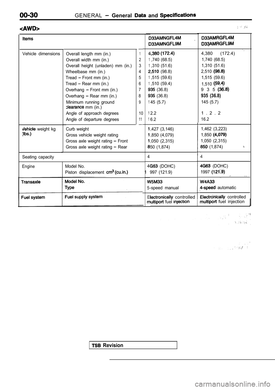
Vehicle dimensions
weight kg
Overall length mm (in.)
Overall width mm (in.)
Overall height (unladen) mm (in.)
Wheelbase mm (in.)
Tread
Front mm (in.)
Tread
Rear mm (in.)
Overhang
Front mm (in.)
Overhang
Rear mm (in.)
Minimum running ground
mm (in.)
Angle of approach degrees
Angle of departure degrees
Curb weight
Gross vehicle weight rating
Gross axle weight rating
Front
Gross axle weight rating
Rear
1
2
3
4 5
6
7
8
9
10
11
Seating capacity
EngineModel No.
Piston displacement
4
1,740 (68.5)
1,310 (51.6)
(98.8)
1,515 (59.6)
1,510 (59.4)
(36.8)
(36.8)
145 (5.7)
4,380 (172.4)
1,740 (68.5)
1,310 (51.6)
2,510
1,515 (59.6)
1,510
9 3 5
935 (36.8)
145 (5.7)
12.2
16.2
,427 (3,146)
,850 (4,079)
,050 (2,315)
50 (1,874)
4
4
1
5
El
1 . 2 . 2
16.2
1,462 (3,223)
1,850
1,050 (2,315)
(1,874)
4
(DOHC)
997 (121.9)
-speed manual
(DOHC)
1997
automatic
controlled controlled
fuel fuel injection
Revision
Page 105 of 2103
CONTENTS
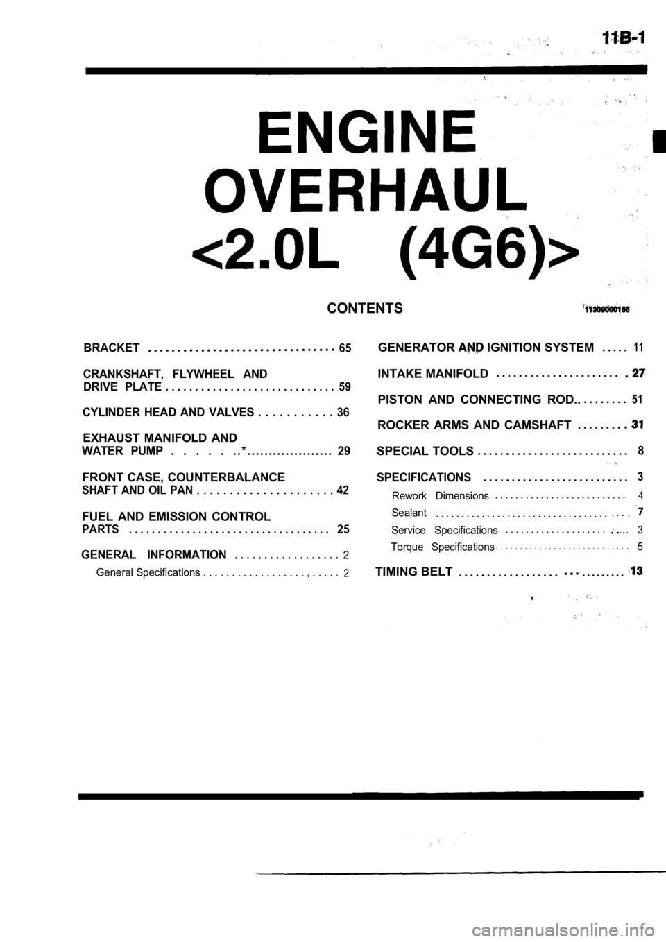
BRACKET65
CRANKSHAFT, FLYWHEEL ANDDRIVE PLATE
. . . . . . . . . . . . . . . . . . . . . . . . . . . . .59
CYLINDER HEAD AND VALVES . . . . . . . . . . . 36
EXHAUST MANIFOLD AND
WATER PUMP. . . . . . . * . . . . . . . . . . . . . . . . . . . .29
FRONT CASE, COUNTERBALANCE
SHAFT AND OIL PAN . . . . . . . . . . . . . . . . . . . . . 42
FUEL AND EMISSION CONTROL
PARTS. . . . . . . . . . . . . . . . . . . . . . . . . . . . . . . . . . .25
GENERAL INFORMATION. . . . . . . . . . . . . . . . . .2
General Specifications . . . . . . . . . . . . . . . . . . , . . . . .2
GENERATOR IGNITION SYSTEM. . . . .11
INTAKE MANIFOLD. . . . . . . . . . . . . . . . . . . . . .
PISTON AND CONNECTING ROD..
. . . . . . . .51
ROCKER ARMS AND CAMSHAFT. . . . . . . .
SPECIAL TOOLS
. . . . . . . . . . . . . . . . . . . . . . . . . . .8
SPECIFICATIONS. . . . . . . . . . . . . . . . . . . . . . . . . .3
Rework Dimensions. . . . . . . . . . . . . . . . . . . . . . . . . .4
Sealant. . . . . . . . . . . . . . . . . . . . . . . . . . . . . . . . . .. . ..
Service Specifications. . . . . . . . . . . . . . . . . . . ....3
Torque Specifications. . . . . . . . . . . . . . . . . . . . . . . . . . . .5
TIMING BELT
. . . . . . . . . . . . . . . . . .. . . . . . . . .
,
Page 108 of 2103
![MITSUBISHI SPYDER 1990 Service Repair Manual ENGINE OVERHAUL
Items Standard value
Piston ring end gap mm (in.)
Piston pin O.D. mm (in.)
0 . 8
Oil 9 . 8
21
Piston pin press-in load (Ibs.)
[Room temperature]
Crankshaft pin MITSUBISHI SPYDER 1990 Service Repair Manual ENGINE OVERHAUL
Items Standard value
Piston ring end gap mm (in.)
Piston pin O.D. mm (in.)
0 . 8
Oil 9 . 8
21
Piston pin press-in load (Ibs.)
[Room temperature]
Crankshaft pin](/manual-img/19/57345/w960_57345-107.png)
ENGINE OVERHAUL
Items Standard value
Piston ring end gap mm (in.)
Piston pin O.D. mm (in.)
0 . 8
Oil 9 . 8
21
Piston pin press-in load (Ibs.)
[Room temperature]
Crankshaft pin oil clearance mm (in.) 17,500
Connecting rod big end side clearance mm (in.)
Crankshaft, flywheel and drive plate
Bearing cap bolt shank length mm (in.)
0 . 4
Crankshaft end play mm (in.)
Crankshaft journal O.D. mm (in.) 0 . 2 5
57 (2.24)
pin O.D. mm (in.) 42 (1.77)
Crankshaft journal oil clearance mm (in.)
to cylinder clearance mm (in.)
0 . 1
block flatness of gasket surface mm (in.) 0.05 0.1
block grinding limit of gasket surface mm (in.)l 0.2‘Total resurfacing depth of both cylinder head and cylinder block
block overall height mm (in.)283.9-284.1
(11.177-11.185)
block I.D. mm (in.) 85.0 (3.35)
TSBRevision
REWORK DIMENSIONS
Items
Cylinder head and valve
Oversize rework dimensions of valve guide0.05 O.S.
hole (both intake and exhaust) mm (in.) 0.25 O.S.
0.50
Intake oversize rework 0.3
dimensions of valve seat hole mm (in.)
0.6 O.S.
Exhaust oversize rework dimensions of valve 0.3 O.S.
seat hole
mm (in.)0.6 O.S.
Crankshaft, flywheel and drive plate
Crankshaft out of roundness and taper of journal an d pin mm (in.)
Standard value
12.25-12.27 ,
,
Max. 0.01
NOTE
O.D.: Outer diameter
I.D.: Inner diameter
Oversize diameter
Page 244 of 2103
11ENGINE OVERHAUL Cylinder Head
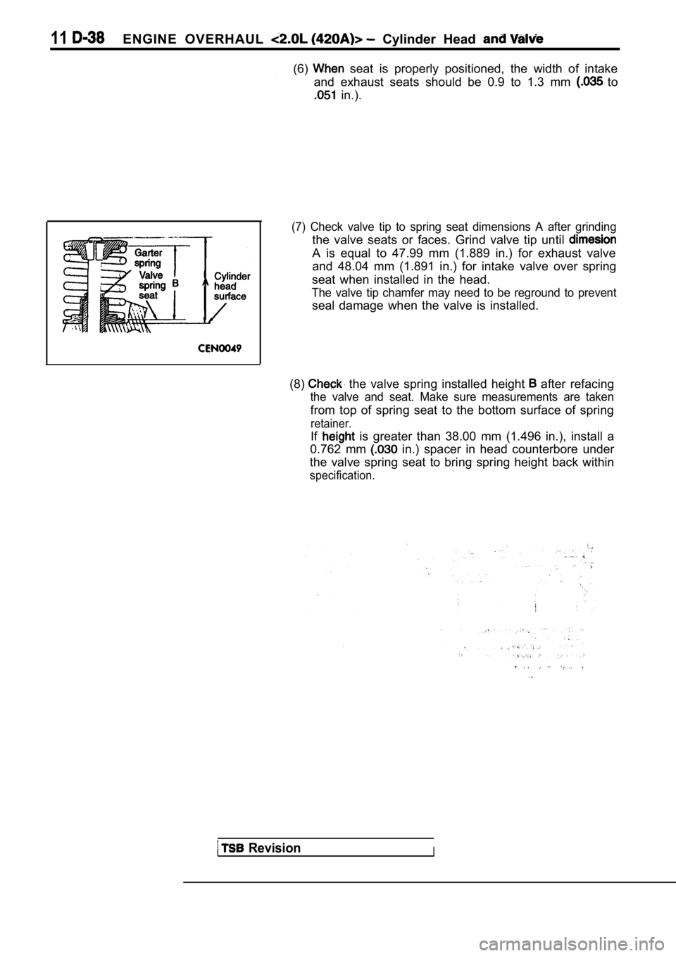
(6) seat is properly positioned, the width of intake
and exhaust seats should be 0.9 to 1.3 mm
to
in.).
(7) Check valve tip to spring seat dimensions A aft er grinding
the valve seats or faces. Grind valve tip until
A is equal to 47.99 mm (1.889 in.) for exhaust valv e
and 48.04 mm (1.891 in.) for intake valve over spri ng
seat when installed in the head.
The valve tip chamfer may need to be reground to pr event
seal damage when the valve is installed.
(8)
the valve spring installed height after refacing
the valve and seat. Make sure measurements are take n
from top of spring seat to the bottom surface of spring
retainer.
If is greater than 38.00 mm (1.496 in.), install a
0.762 mm
in.) spacer in head counterbore under
the valve spring seat to bring spring height back w ithin
specification.
RevisionI
Page 314 of 2103
ENGINE OVERHAUL
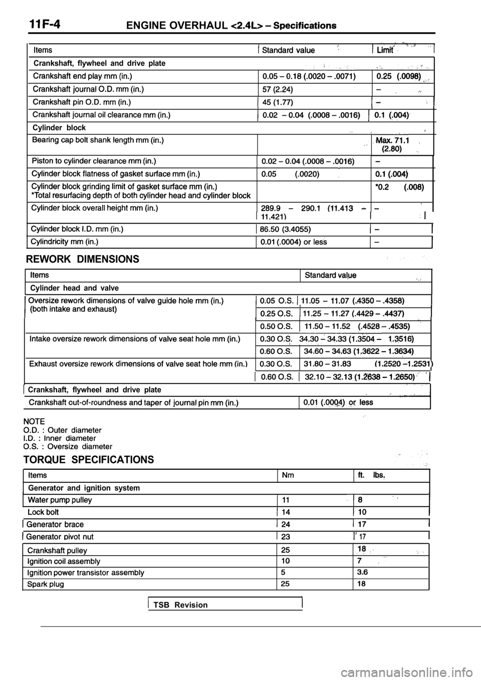
Crankshaft, flywheel and drive plate,
Cylinder block
REWORK DIMENSIONS
Cylinder head and valve
Crankshaft, flywheel and drive plate
TORQUE SPECIFICATIONS
Generator and ignition system
I‘
TSB Revision
Page 1574 of 2103
REAR AXLE Differential Carrier
Fe gauge
Bearing cap
Al
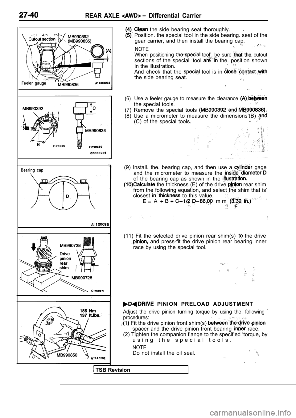
the side bearing seat thoroughly..
Position. the special tool in the side bearing. se
at of the
gear carrier, and then install the bearing cap.
NOTE
When positioning tool’, be sure cutout
sections of the special ‘tool the. position shown
in the illustration.
And check that the tool is in
the side bearing seat.
.
(6)Use a feeler gauge to measure the clearance
the special tools.
(7) Remove the special tools
(8) Use a micrometer to measure the dimensions’(B)
(C) of the special tools.
(9) Install. the. bearing cap, and then use a gage
and the micrometer to measure the
of the bearing cap as shown in the
the thickness (E) of the drive rear shim
from the following equation, and select the shim th at is’
closest
to this value.
A m m
(11) Fit the selected drive pinion rear shim(s) the drive
and press-fit the drive pinion rear bearing inner
race by using the special tool.
P I N I O N P R E L O A D A D J U S T M E N T
Adjust the drive pinion turning torque by using the , following
procedures:
Fit the drive pinion front shim(s)
spacer and the drive pinion front bearing race.
(2) Tighten the companion flange to the specified ‘ torque, by
u s i n g t h e s p e c i a l t o o l s .
NOTE
Do not install the oil seal.
. .
TSB Revision
Page 1836 of 2103
BODY Windshield and Window Glass
A
Section
Quarter
Door window glassSash weatherstrip
up-stopup-stopinstallation bolt
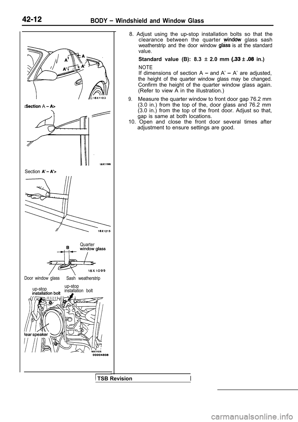
8. Adjust using the up-stop installation bolts so t
hat the
clearance between the quarter
glass sash
weatherstrip and the door window is at the standard
value.
Standard value (B): 8.3 2.0 mm in.)
NOTE
If dimensions of section A and A’ A’ are adjusted,
the height of the quarter window glass may be chang ed.
Confirm the height of the quarter window glass again.
(Refer to view A in the illustration.)
9.Measure the quarter window to front door gap 76.2 m m
(3.0 in.) from the top of the, door glass and 76.2 mm
(3.0 in.) from the top of the front door. Adjust so that,
gap is same at both locations.
10. Open and close the front door several times aft er
adjustment to ensure settings are good.
TSB Revision
Page 1872 of 2103
42-48BODY Door
Delta sashInner stabilizer
track
ON-VEHICLE SERVICE
DOOR FIT ADJUSTMENT
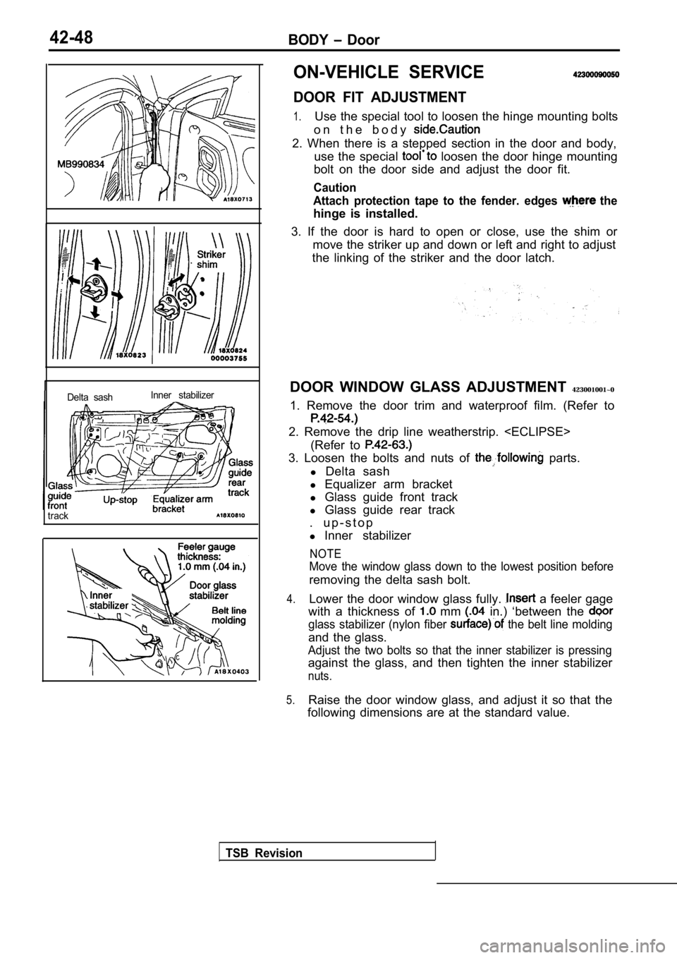
1.Use the special tool to loosen the hinge mounting b
olts
o n t h e b o d y
2. When there is a stepped section in the door and body,
use the special
loosen the door hinge mounting
bolt on the door side and adjust the door fit.
Caution
Attach protection tape to the fender. edges
the
hinge is installed.
3. If the door is hard to open or close, use the sh im or
move the striker up and down or left and right to a djust
the linking of the striker and the door latch.
DOOR WINDOW GLASS ADJUSTMENT 423001001~0
1. Remove the door trim and waterproof film. (Refer to
2. Remove the drip line weatherstrip.
(Refer to
3. Loosen the bolts and nuts of parts.
l Delta sash
l Equalizer arm bracket
l Glass guide front track
l Glass guide rear track
. u p - s t o p
l Inner stabilizer
NOTE
Move the window glass down to the lowest position b efore
removing the delta sash bolt.
4.Lower the door window glass fully. a feeler gage
with a thickness of
mm in.) ‘between the
glass stabilizer (nylon fiber the belt line molding
and the glass.
Adjust the two bolts so that the inner stabilizer i s pressing
against the glass, and then tighten the inner stabi lizer
nuts.
5.Raise the door window glass, and adjust it so that the
following dimensions are at the standard value.
TSB Revision