1990 MITSUBISHI SPYDER brake light
[x] Cancel search: brake lightPage 52 of 2103

GENERAL Maintenance Service
2.Check the wheel cylinder boots for evidence, a’ brake
fluid leak. Visually check the
boots for tears or
cracks. (A slight amount of fluid on the boot may not
be a leak, but may be preservative assembly.)
Caution
The shoes for the right and left be,
replaced at the same time.
Never split or intermix brake
sets.
All four shoes must be replaced as a set.
Thickness of lining
Limit: 1.0 mm in.)
17. BRAKE HOSES (Check for
leaks)
Check of brake hoses and tubing should be
brake service operations.
The hoses should be checked for:
1.Correct length, severe surface cracking, pulling, scuffing
or worn spots. (If the fabric casing of the hoses i s exposed
by cracks of abrasion in the rubber hose cover, the hoses
should be replaced. Eventual deterioration of may
occur with possible bursting failure.)
2. Faulty installation, casing twisting or interfer ence
wheel,’ tire or chassis.
18. BALL JOINT AND STEERING SEALS
(Check for grease leaks damage)
1. These components, which are permanently lubricat ed
at the factory, do not require periodic lubrication. Damaged
seals and boots should be replaced to prevent leakage
or contamination of the grease.
2.Check the dust cover and boots for proper sealing, leakage
and damage. Replace them if defective.
19. DRIVE SHAFT BOOTS (Check for leaks
and damage)
1. These components, which are permanently lubricat ed
at the factory, do not require periodic Damaged
boots should be replaced to prevent leakage or contamina-
tion of the grease.
2.Check the boots for proper sealing, leakage and damage.
Replace it if defective.
AXLE OIL (Check oil level)-AWD
Remove the filler plug and check the oil level at bottom of
filler hole. If the oil level is slightly below the filler hole, it
is in satisfactory condition.
Page 385 of 2103
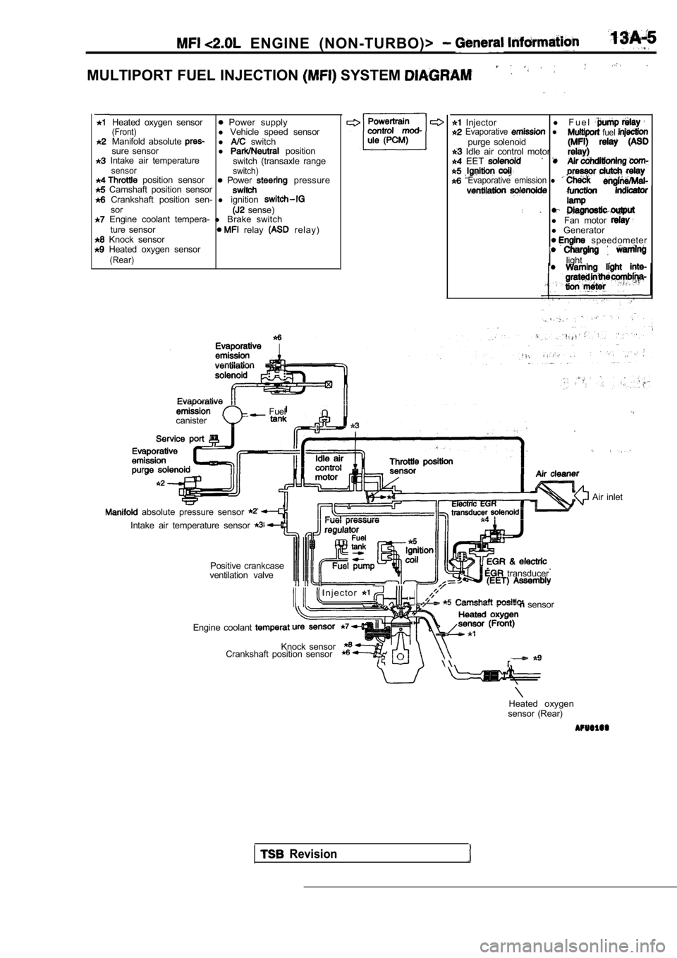
ENGINE (NON-TURBO)>
MULTIPORT FUEL INJECTION SYSTEM
Heated oxygen sensor Power supply(Front)l Vehicle speed sensor
Manifold absolute l switch
sure sensor l position Intake air temperature
switch (transaxle rangesensor switch) position sensor Power pressure Camshaft position sensor Crankshaft position sen- l ignitionsor sense) Engine coolant tempera- l Brake switch
ture sensor relay r e l a y ) Knock sensor Heated oxygen sensor(Rear)
Injector l
F u e l Evaporative l fuel purge solenoid Idle air control motor EET
“Evaporative emission l
.l Fan motor l Generator speedometer
light
.
Fuel
canister
absolute pressure sensor
Intake air temperature sensor
Positive crankcase
ventilation valve
I n j e c t o r
transducer
sensor
Engine coolant
Knock sensor
Crankshaft position sensor
Air inlet
Heated oxygen
sensor (Rear)
Revision
Page 619 of 2103
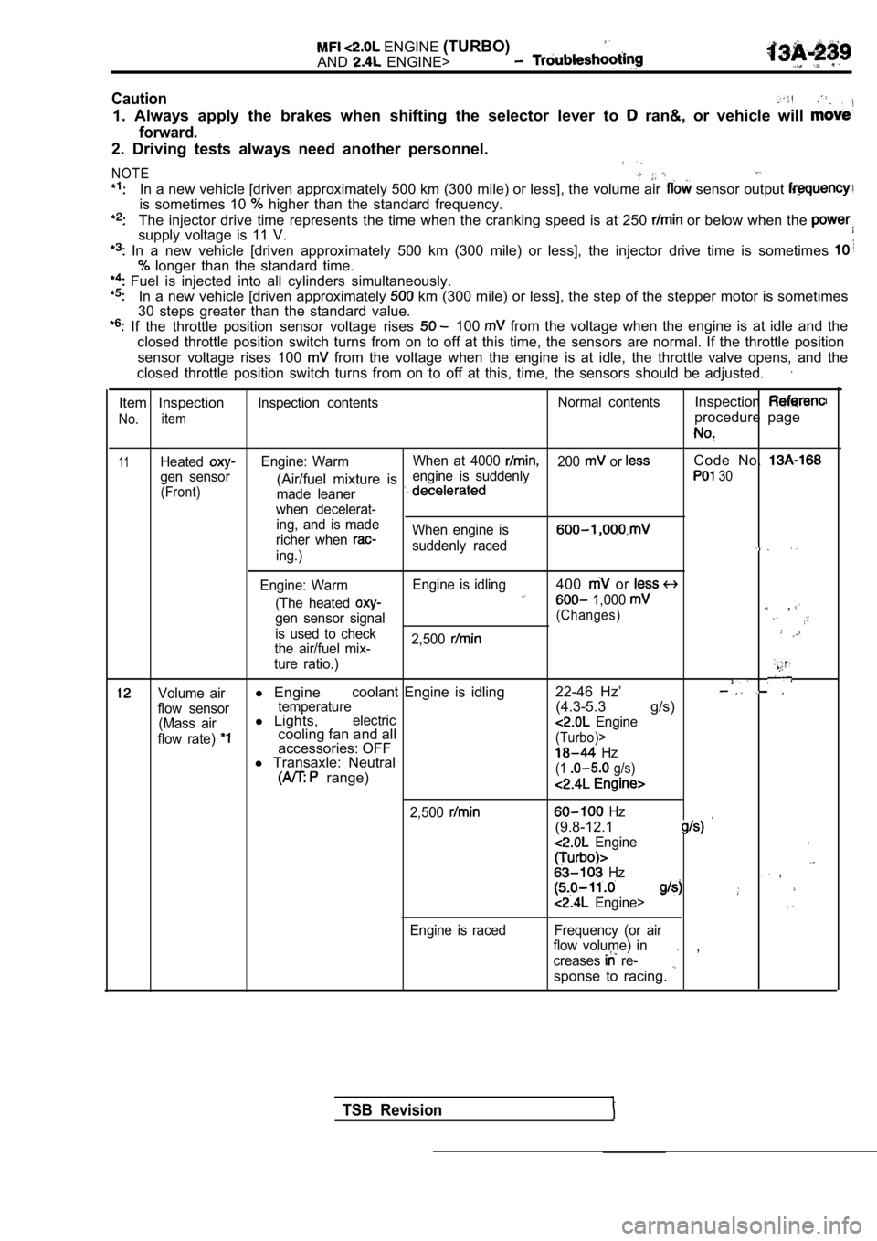
ENGINE (TURBO)
AND ENGINE>
Caution
1. Always apply the brakes when shifting the select or lever to ran&, or vehicle will
forward.
2. Driving tests always need another personnel.
NOTE
In a new vehicle [driven approximately 500 km (300 mile) or less], the volume air sensor output
is sometimes 10 higher than the standard frequency.
The injector drive time represents the time when the cranking speed is at 250 or below when the
supply voltage is 11 V.
In a new vehicle [driven approximately 500 km (300 mile) or less], the injector drive time is sometimes
longer than the standard time.
Fuel is injected into all cylinders simultaneously.
In a new vehicle [driven approximately km (300 mile) or less], the step of the stepper mo tor is sometimes
30 steps greater than the standard value.
If the throttle position sensor voltage rises 100 from the voltage when the engine is at idle and th e
closed throttle position switch turns from on to of f at this time, the sensors are normal. If the throttle position
sensor voltage rises 100
from the voltage when the engine is at idle, the t hrottle valve opens, and the
closed throttle position switch turns from on to of f at this, time, the sensors should be adjusted.
Item Inspection
No.item
Inspection contents Normal contentsInspection
procedure page
11HeatedEngine: WarmWhen at 4000 200 or Code No.
gen sensor engine is suddenly(Air/fuel mixture is 30
(Front)
made leaner
when decelerat- ing, and is made
richer when
When engine is
suddenly raceding.)
Engine: Warm Engine is idling
400 or
(The heated 1,000 ,gen sensor signal(Changes)
is used to check
2,500
the air/fuel mix-
ture ratio.)
Volume airl Engine coolant Engine is idling 22-46 Hz’
flow sensortemperature(4.3-5.3 g/s)
(Mass airl
Lights,electric
flow rate) cooling fan and all Engine
accessories: OFF(Turbo)>
l Transaxle: Neutral Hz
range)(1 g/s)
2,500
Engine is raced
Hz
(9.8-12.1
Engine,
Hz ,
Engine>
Frequency (or air
flow volume) in
creases
re- ,
sponse to racing.
TSB Revision
Page 753 of 2103
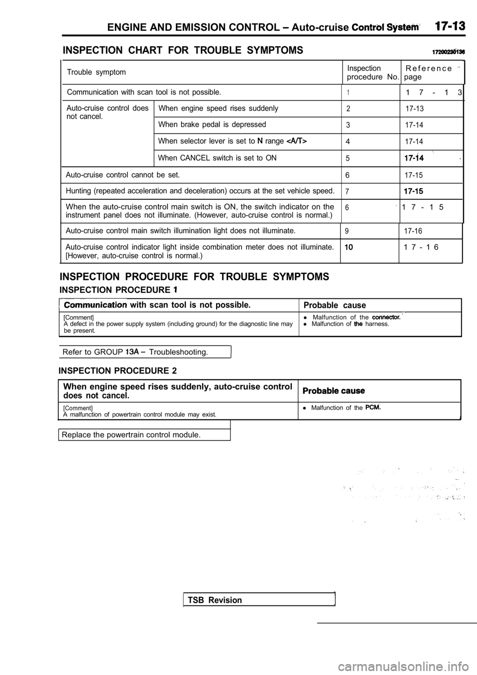
ENGINE AND EMISSION CONTROL Auto-cruise
INSPECTION CHART FOR TROUBLE SYMPTOMS
Trouble symptomInspectionR e f e r e n c e
procedure No. page
Communication with scan tool is not possible.11 7 - 1 3
Auto-cruise control doesWhen engine speed rises suddenly217-13not cancel.
When brake pedal is depressed
3 17-14
When selector lever is set to range 417-14
When CANCEL switch is set to ON5.
Auto-cruise control cannot be set. 617-15
Hunting (repeated acceleration and deceleration) occurs at the set vehicle speed.7
When the auto-cruise control main switch is ON, the switch indicator on the6 1 7 - 1 5instrument panel does not illuminate. (However, aut o-cruise control is normal.)
Auto-cruise control main switch illumination light does not illuminate.
917-16
Auto-cruise control indicator light inside combinat ion meter does not illuminate.1 7 - 1 6
[However, auto-cruise control is normal.)
INSPECTION PROCEDURE FOR TROUBLE SYMPTOMS
INSPECTION PROCEDURE
with scan tool is not possible.
Probable cause
[Comment] l
Malfunction of the A defect in the power supply system (including grou nd) for the diagnostic line mayl Malfunction of harness.
be present.
Refer to GROUP
Troubleshooting.
INSPECTION PROCEDURE 2 When engine speed rises suddenly, auto-cruise contr ol
does not cancel.
[Comment]A malfunction of powertrain control module may exist.
Replace the powertrain control module. l
Malfunction of the
TSB Revision
Page 754 of 2103
![MITSUBISHI SPYDER 1990 Service Repair Manual ENGINE AND EMISSION CONTROL Auto-cruise Control System
INSPECTION PROCEDURE 3
When brake pedal is depressed,, auto-cruise control does not
cancel.
[Comment]A malfunction of the stop li MITSUBISHI SPYDER 1990 Service Repair Manual ENGINE AND EMISSION CONTROL Auto-cruise Control System
INSPECTION PROCEDURE 3
When brake pedal is depressed,, auto-cruise control does not
cancel.
[Comment]A malfunction of the stop li](/manual-img/19/57345/w960_57345-753.png)
ENGINE AND EMISSION CONTROL Auto-cruise Control System
INSPECTION PROCEDURE 3
When brake pedal is depressed,, auto-cruise control does not
cancel.
[Comment]A malfunction of the stop light switch or stop ligh t circuit may exist.
Probable cause
l Malfunction of the stop light switch.
l Malfunction of the connector.
l Malfunction of the
l Malfunction of the PCM.
Stop light switch check.
(Refer to
OK
Measure at stop
switch connector
lDisconnect the connector and mea-sure at the harness side.
l Voltage between terminal (1) and
ground positive voltage
following connectors:
NG
63 and
NG
Check troubleNGsymp Check the l i g h t a n d P C M . R e p a i r ,
OK Check trouble symptom.
Replace the PCM.
light switch and the
ground.
,
INSPECTION PROCEDURE 4
When selector lever is set to range, auto-cruise control does
not cancel.
[Comment]An open-circuit in the output signal circuit in IN range may be present.
OK
and.
TSB Revision
Inspect thebetween the NG
transaxle range switch and PCM.
OK
the PCM.
INSPECTION PROCEDURE 5
When auto-cruise control CANCEL switch is set to ON ,
auto-cruise control does not cancel. Probable cause
[Comment]An open-circuit inside the CANCEL switch may be pre
sent.l
Malfunction of the auto-cruise control switch.
Replace the auto-cruise control
Page 759 of 2103
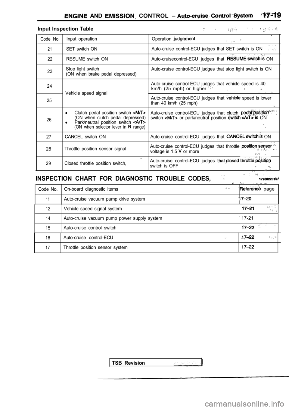
AND CONTROL
Input Inspection Table
.
Code No.Input operation Operation
21SET switch ONAuto-cruise control-ECU judges that SET switch is O
N
22RESUME switch ON Auto-cruisecontrol-ECU judges that ON
23 Stop light switch
(ON when brake pedal depressed) Auto-cruise control-ECU judges that stop light swit
ch is ON
24
25
26Auto-cruise control-ECU judges that vehicle speed i s 40
km/h (25 mph) or higher ,Vehicle speed signal
Auto-cruise control-ECU judges that speed is lower
than 40 km/h (25 mph)
lClutch pedal position switch Auto-cruise control-ECU judges that clutch (ON when clutch pedal depressed) Park/neutral position switch switch or park/neutral position ONl(ON when selector lever in range)
27 CANCEL switch ON Auto-cruise control-ECU judges that
ON
28 Throttle position sensor signal Auto-cruise control-ECU judges that throttle
voltage is 1.5 or more
29Closed throttle position switch,Auto-cruise control-ECU judges
switch is OFF
INSPECTION CHART FOR DIAGNOSTIC TROUBLE CODES,
Code No.
On-board diagnostic items page
11Auto-cruise vacuum pump drive system
12
14
15
Vehicle speed signal system
Auto-cruise vacuum pump power supply system
Auto-cruise control switch
17-21
.
16
17
Auto-cruise control-ECU
Throttle position sensor system
TSB Revision
Page 763 of 2103
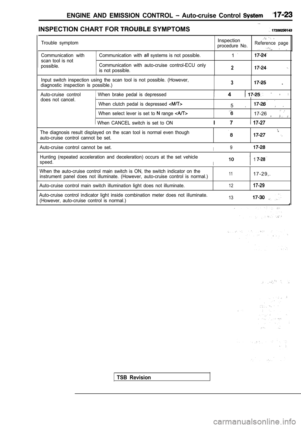
ENGINE AND EMISSION CONTROL Auto-cruise Control
INSPECTION CHART FOR SYMPTOMS
Communication with
scan tool is not
possible. Communication with systems is not possible.
Communication with auto-cruise control-ECU only
is not possible.1
2
Input switch inspection using the scan tool is not possible. (However,
diagnostic inspection is possible.)3 .
Auto-cruise control When brake pedal is depressed 4 does not cancel. When clutch pedal is depressed
When select lever is set to range
When CANCEL switch is set to ON
5
17-26
I 7 17-27
Trouble symptomInspection
procedure No.Reference page
The diagnosis result displayed on the scan tool is normal even though
auto-cruise control cannot be set.
Auto-cruise control cannot be set.I9
Hunting (repeated acceleration and deceleration) oc curs at the set vehicle
speed.I1
When the auto-cruise control main switch is ON, the switch indicator on the
instrument panel does not illuminate. (However, aut o-cruise control is normal.)
Auto-cruise control main switch illumination light does not illuminate.111 7 - 2 9 , .
1217-29
Auto-cruise control indicator light inside combinat ion meter does not illuminate.
(However, auto-cruise control is normal.)13
TSB Revision
Page 765 of 2103
![MITSUBISHI SPYDER 1990 Service Repair Manual ENGINE AND EMISSION System
.,
INSPECTION PROCEDURE 3
Input switch inspection using the scan tool is pdssible.
(However, diagnostic inspection is possible.)
I
[Comment]A malfunction MITSUBISHI SPYDER 1990 Service Repair Manual ENGINE AND EMISSION System
.,
INSPECTION PROCEDURE 3
Input switch inspection using the scan tool is pdssible.
(However, diagnostic inspection is possible.)
I
[Comment]A malfunction](/manual-img/19/57345/w960_57345-764.png)
ENGINE AND EMISSION System
.,
INSPECTION PROCEDURE 3
Input switch inspection using the scan tool is pdssible.
(However, diagnostic inspection is possible.)
I
[Comment]A malfunction of auto-cruise control switch circuit system may be present.l
Malfunction of the auto-cruise control l Malfunction of the clock spring .
l of the connector.
l Malfunction of the harness.
.
NG
(Refer to
Measure at clock spring connector
l sure at the harness side
l Voltage between terminal (2) and
groundOK: Battery positive voltage
OK
Check trouble symptom.
C h e c k t r o u b l e spring and auto-cruise
INSPECTION PROCEDURE 4
When brake pedal is depressed, auto-cruise control does not
cancel.Probable , ,
[Comment]A malfunction of stop light switch or a malfunction of stop light circuit may be present.l
Malfunction of the stop light switch.
l Malfunction of the connector.
l Malfunction of. the
l Malfunction of the auto-cruise control-ECU.
Does stop
illuminate?
No
Replace the auto-cruise control-ECU.
lDisconnect the connector and mea-sure at the harness side.
Check trouble symptom.Check the following connectors:
TSB Revision