1990 MITSUBISHI SPYDER brake light
[x] Cancel search: brake lightPage 1060 of 2103
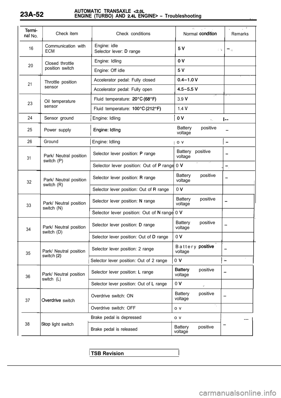
AUTOMATIC TRANSAXLE
ENGINE (TURBO) AND ENGINE> Troubleshooting
No.Check item
Check conditionsNormalRemarks
16Communication withEngine: idle
ECMSelector lever: range
20Closed throttle
position switch Engine: Idling
Engine: Off idle
21
23
24
25
26
31
32
33
34
35
36
37
38
Throttle position
sensor Accelerator pedal: Fully closed
Accelerator pedal: Fully open
Oil temperature
sensor Fluid temperature:
Fluid temperature:
3.9
1.4
Sensor ground Engine: IdlingI--
Power supplyBattery positive
voltage
Ground Engine: IdlingIo v
Park/ Neutral position
Selector lever position: rangeBattery positive
switch (P) voltage
Selector lever position: Out of range 0
Park/ Neutral position
Selector lever position: rangeBattery positive
switch (R) voltage
Selector lever position: Out of
range0
Park/ Neutral position Selector lever position: rangeBattery positive
switch (N) voltageSelector lever position: Out of range 0
Park/ Neutral position
Selector lever position: rangeBattery positive
switch (D) voltage
Selector lever position: Out of
range0
Park/ Neutral position Selector lever position: 2 rangeB a t t e r y
switchvoltage
Selector lever position: Out of 2 range 0
Park/ Neutral position
Selector lever position: range positive
switch (L)voltage
Selector lever position: Out of
range0
switch Overdrive switch: ON
Overdrive switch: OFF
Battery positive
voltage
o v
Brake pedal is depressedo v--- I
light switch Brake pedal is releasedBattery positive voltage
TSB Revision
Page 1148 of 2103
AUTOMATIC TRANSAXLE
ENGINE (NON-TURBO)> Troubleshootihg
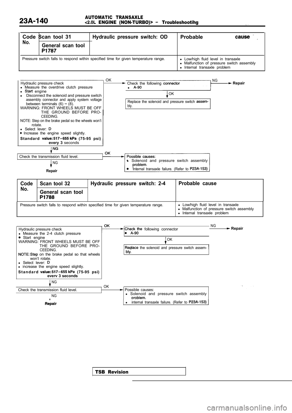
Code Scan tool 31Hydraulic pressure switch: ODProbable
No.General scan tool
Pressure switch falls to respond within specified time for given temperature range.
l Low/high fluid level in transaxle
l Malfunction of pressure switch assembly
l Internal transaxle problem
OKNGHydraulic pressure check Check the following Repair
l Measure the overdrive clutch pressure
l
l engine
l Disconnect the solenoid and pressure switchOK
assembly connector and apply system voltage
between terminals (6) (8).
WARNING: FRONT WHEELS MUST BE OFFReplace the solenoid and pressure switch bly.
THE GROUND BEFORE PRO-CEEDING.
NOTE: Step on the brake pedal so the wheels won’t rotate.
l Select lever: Increase the engine speed slightly.
S t a n d a r d
(75-95 psi)
every 3 seconds
Check the transmission fluid level.
NG
Repair
l Solenoid and pressure switch assembly
Internal transaxle failure. (Refer to
Code Scan tool 32 Hydraulic pressure switch: 2-4 Probable cause
No.General scan tool
TSB Revision
Pressure switch falls to respond within specified t
ime for given temperature range.l
Low/high fluid level in transaxle
l Malfunction of pressure switch assembly
l Internal transaxle problem
Hydraulic pressure check
l Measure the 2-4 clutch pressure
Start engine
following connector
WARNING: FRONT WHEELS MUST BE OFF THE GROUND BEFORE PRO-
CEEDING. on the brake pedal so that wheels
won’t rotate.
l Select lever:
l increase the engine speed slightly.
S t a n d a r d
(75-95 psi)
everv 3 seconds
NGOK
NG Repair
OK
the solenoid and pressure switch assem-
Check the transmission fluid level.
NG
Possible causes:
l Solenoid and pressure switch assembly
linternal transaxle failure. (Refer to
Page 1174 of 2103
AUTOMATIC TRANSAXLE
ENGINE (NON-TURBO)> On-vehicle Service
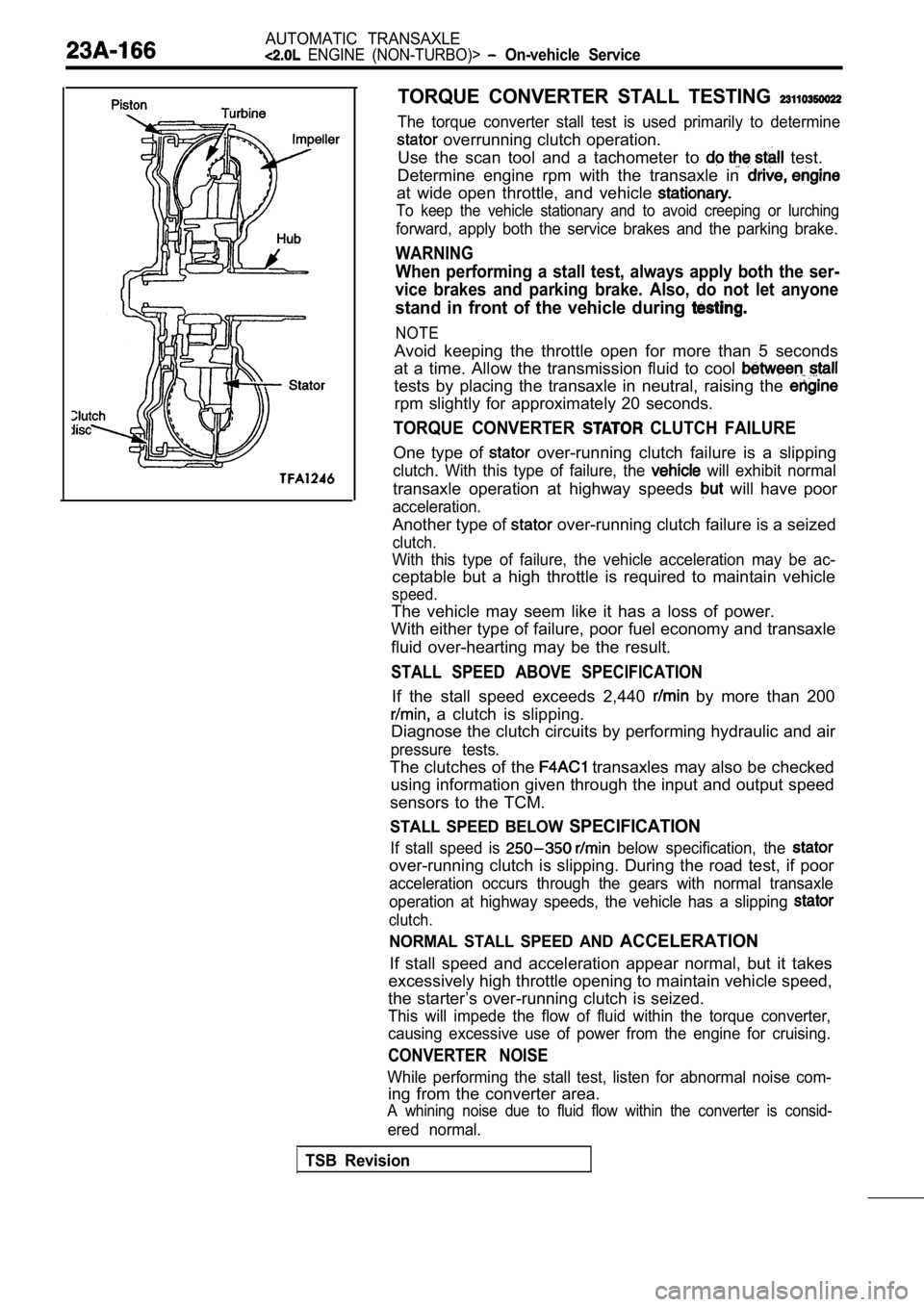
TORQUE CONVERTER STALL TESTING
The torque converter stall test is used primarily to determine
overrunning clutch operation.
Use the scan tool and a tachometer to
test.
Determine engine rpm with the transaxle in
at wide open throttle, and vehicle
To keep the vehicle stationary and to avoid creepin g or lurching
forward, apply both the service brakes and the parking brake.
WARNING
When performing a stall test, always apply both the ser-
vice brakes and parking brake. Also, do not let any one
stand in front of the vehicle during
NOTE
Avoid keeping the throttle open for more than 5 seconds
at a time. Allow the transmission fluid to cool
tests by placing the transaxle in neutral, raising the
rpm slightly for approximately 20 seconds.
TORQUE CONVERTER CLUTCH FAILURE
One type of over-running clutch failure is a slipping
clutch. With this type of failure, the will exhibit normal
transaxle operation at highway speeds will have poor
acceleration.
Another type of over-running clutch failure is a seized
clutch.
With this type of failure, the vehicle acceleration may be ac-
ceptable but a high throttle is required to maintai n vehicle
speed.
The vehicle may seem like it has a loss of power.
With either type of failure, poor fuel economy and transaxle
fluid over-hearting may be the result.
STALL SPEED ABOVE SPECIFICATION
If the stall speed exceeds 2,440 by more than 200
a clutch is slipping.
Diagnose the clutch circuits by performing hydrauli c and air
pressure tests.
The clutches of the transaxles may also be checked
using information given through the input and outpu t speed
sensors to the TCM.
STALL SPEED BELOW SPECIFICATION
If stall speed is below specification, the
over-running clutch is slipping. During the road te st, if poor
acceleration occurs through the gears with normal t ransaxle
operation at highway speeds, the vehicle has a slip ping
clutch.
NORMAL STALL SPEED AND ACCELERATION
If stall speed and acceleration appear normal, but it takes
excessively high throttle opening to maintain vehic le speed,
the starter’s over-running clutch is seized.
This will impede the flow of fluid within the torqu e converter,
causing excessive use of power from the engine for cruising.
CONVERTER NOISE
While performing the stall test, listen for abnormal noise com-
ing from the converter area.
A whining noise due to fluid flow within the conver ter is consid-
ered normal.
TSB Revision
Page 1639 of 2103
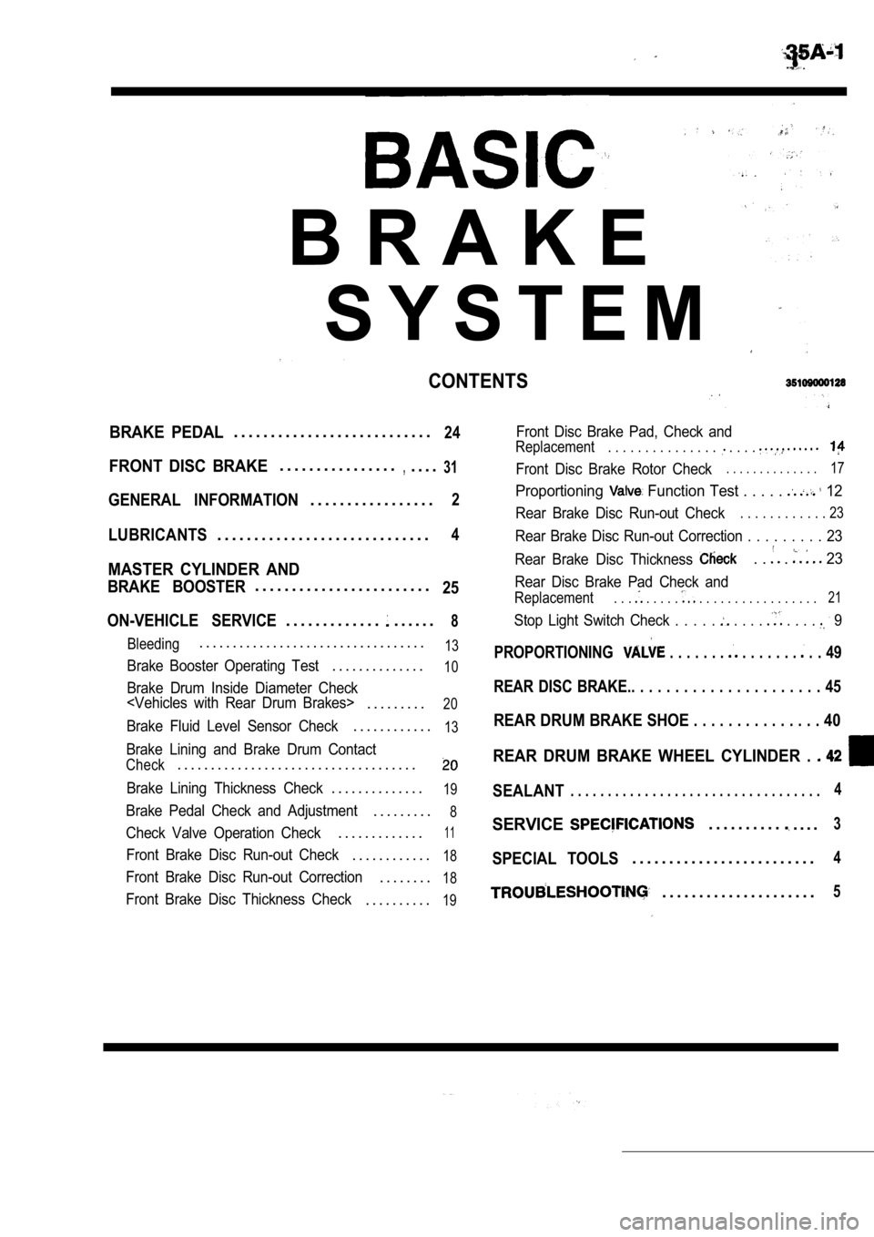
B R A K E
S Y S T E M
CONTENTS
BRAKE PEDAL. . . . . . . . . . . . . . . . . . . . . . . . . . .24
FRONT DISC BRAKE. . . . . . . . . . . . . . . .,. . . .31
GENERAL INFORMATION. . . . . . . . . . . . . . . . .2
LUBRICANTS. . . . . . . . . . . . . . . . . . . . . . . . . . . . .4
MASTER CYLINDER AND
BRAKE BOOSTER. . . . . . . . . . . . . . . . . . . . . . . .25
ON-VEHICLE SERVICE
. . . . . . . . . . . . .. . . . . .8
Bleeding. . . . . . . . . . . . . . . . . . . . . . . . . . . . . . . . . .13
Brake Booster Operating Test. . . . . . . . . . . . . .10
Brake Drum Inside Diameter Check
. . . . . . . . .20
Brake Fluid Level Sensor Check. . . . . . . . . . . .13
Brake Lining and Brake Drum Contact
Check. . . . . . . . . . . . . . . . . . . . . . . . . . . . . . . . . . . .
Brake Lining Thickness Check. . . . . . . . . . . . . .19
Brake Pedal Check and Adjustment. . . . . . . . .8
Check Valve Operation Check. . . . . . . . . . . . .11
Front Brake Disc Run-out Check. . . . . . . . . . . .18
Front Brake Disc Run-out Correction. . . . . . . .18
Front Brake Disc Thickness Check. . . . . . . . . .19
Front Disc Brake Pad, Check and
Replacement. . . . . . . . . . . . . . . . . . .
Front Disc Brake Rotor Check. . . . . . . . . . . . . .17
Proportioning Function Test . . . . . 12
Rear Brake Disc Run-out Check. . . . . . . . . . . . 23
Rear Brake Disc Run-out Correction . . . . . . . . . 23
Rear Brake Disc Thickness
. . . 23
Rear Disc Brake Pad Check and
Replacement. . . . . . . . . . . . . . . . . . . . . . . . . 21
Stop Light Switch Check . . . . . . . . . . . . . 9
PROPORTIONING . . . . . . . . . . . . . . . . 49
REAR DISC BRAKE.. . . . . . . . . . . . . . . . . . . . . . 45
REAR DRUM BRAKE SHOE . . . . . . . . . . . . . . . 40
REAR DRUM BRAKE WHEEL CYLINDER .
SEALANT. . . . . . . . . . . . . . . . . . . . . . . . . . . . . . . . . .4
SERVICE. . . . . . . . . .. . . .3
SPECIAL TOOLS. . . . . . . . . . . . . . . . . . . . . . . . .4
. . . . . . . . . . . . . . . . . . . . .5
Page 1646 of 2103
BASIC BRAKE SYSTEM .,
d o w n ,
Lock nut
TSB Revision
O N - V E H I C L E
BRAKE PEDAL
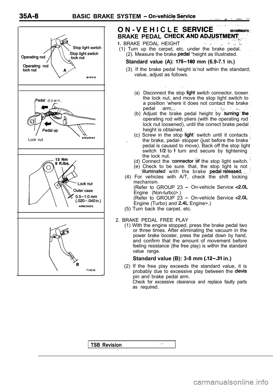
BRAKE PEDAL HEIGHT ,
(1) Turn up the carpet, etc. under the brake pedal.(2). Measure the brake
“height as illustrated.
Standard value (A): mm (6.9-7.1 in.)
(3). If the brake pedal height is’not within the st andard;
value, adjust as follows.
(a)Disconnect the stop switch connector, loosen
the lock nut, and move the stop light switch to
a position ‘where it does not contact the brake
pedal arm,.,
(b) Adjust the brake pedal height by
operating rod with pliers (with the operating rod
lock nut loosened), until the correct brake pedal
height is obtained.
(c) Screw in the stop
switch until it contacts
the brake, pedal- stopper (just before the brake
pedal is caused to move). Back off the stop light
switch
to turn and secure by tightening
the lock nut.
(d) Connect the
the stop light switch.
(e) Check to be sure. that, the stop light is not
with the brake
(4) For vehicles with A/T, check the shift locking
mechanism.
(Refer to GROUP 23 On-vehicle Service
Engine (Non-turbo)>.)
(Refer to GROUP 23 On-vehicle Service
Engine (Turbo) and Engine>.)
(5) Turn back the carpet, etc.
2. BRAKE PEDAL FREE PLAY (1) With the engine stopped, press the brake pedal two
or three times. After eliminating the vacuum in the
power brake booster, press the pedal down by hand,
and confirm that the amount of movement before
feeling resistance (the free play) is within the st andard
value range.
Standard value (B): 3-8 mm in.)
(2) If the free play exceeds the standard value, it is
probably due to excessive play between the
pin and brake pedal arm.
Check for excessive clearance and replace faulty pa rts
as required.
Page 1647 of 2103
BASIC BRAKE SYSTEM
CLEARANCEB E T W E E N B R A K E A N D
REWALL
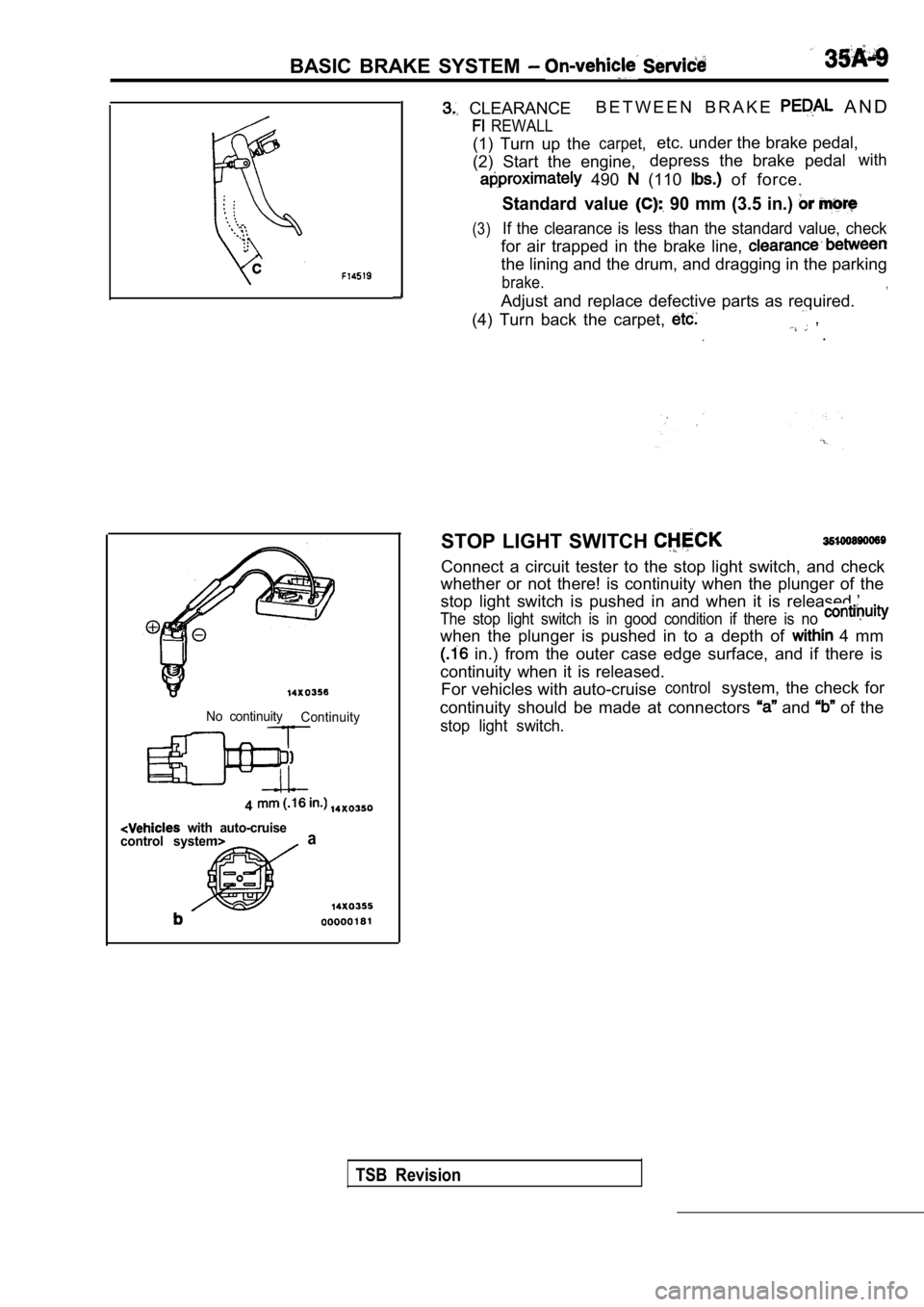
(1) Turn up thecarpet,etc. under the brake pedal,
(2) Start the engine, depress the brake pedal
with
490 (110 of force.
Standard value 90 mm (3.5 in.)
(3)If the clearance is less than the standard value, c
heck
for air trapped in the brake line,
the lining and the drum, and dragging in the parkin g
brake.
Adjust and replace defective parts as required.
(4) Turn back the carpet,
, .
No continuity Continuity
4
with auto-cruise
control systema
STOP LIGHT SWITCH
Connect a circuit tester to the stop light switch, and check
whether or not there! is continuity when the plunge r of the
stop light switch is pushed in and when it is relea sed.’
The stop light switch is in good condition if there is no
when the plunger is pushed in to a depth of 4 mm
in.) from the outer case edge surface, and if ther e is
continuity when it is released. For vehicles with auto-cruise
controlsystem, the check for
continuity should be made at connectors
and of the
stop light switch.
TSB Revision
Page 1648 of 2103
BASIC BRAKE SYSTEM On-vehicle Service
GoodNo good
000001
When engine isWhen engine isstopped started
No goodGood
00000184BRAKE BOOSTER OPERATING
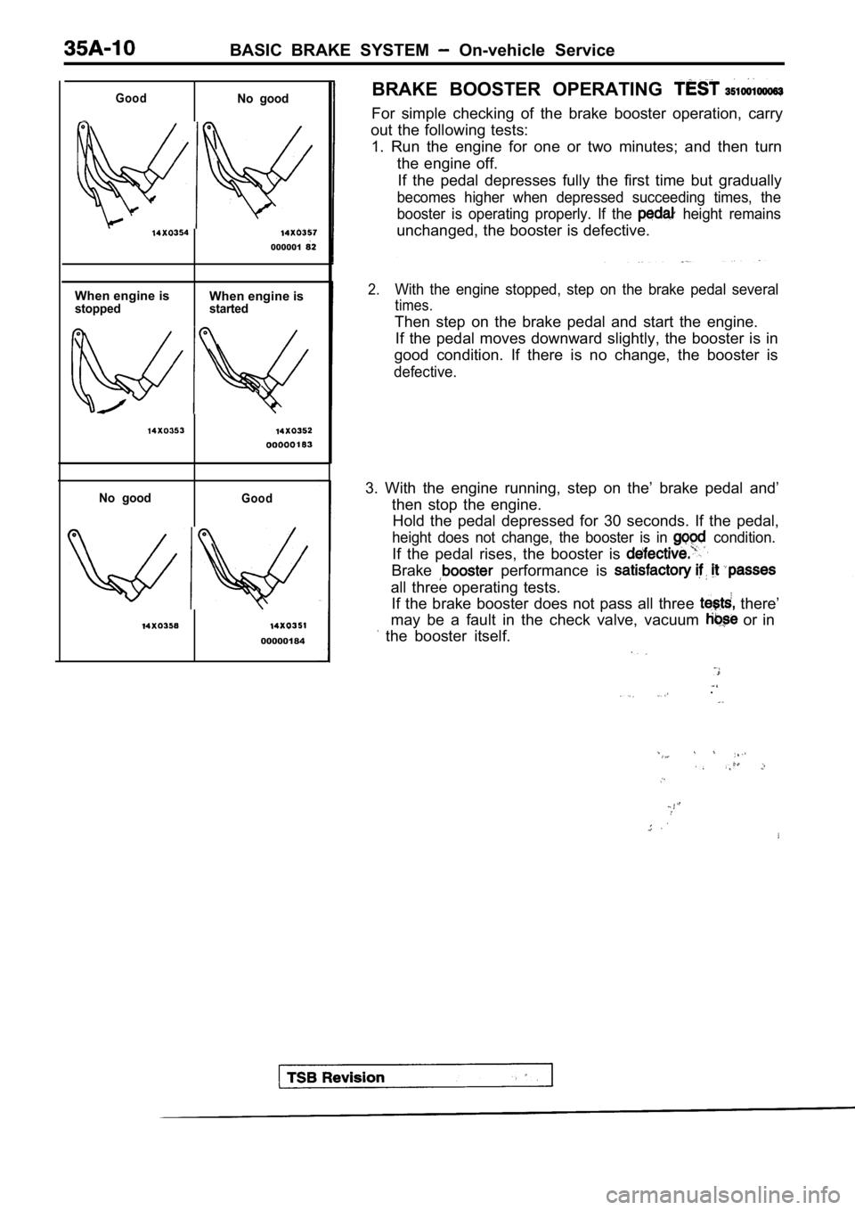
For simple checking of the brake booster operation,
carry
out the following tests: 1. Run the engine for one or two minutes; and then turn
the engine off. If the pedal depresses fully the first time but gra dually
becomes higher when depressed succeeding times, the
booster is operating properly. If the
height remains
unchanged, the booster is defective.
2.With the engine stopped, step on the brake pedal se veral
times.
Then step on the brake pedal and start the engine.
If the pedal moves downward slightly, the booster i s in
good condition. If there is no change, the booster is
defective.
3. With the engine running, step on the’ brake peda l and’
then stop the engine. Hold the pedal depressed for 30 seconds. If the ped al,
height does not change, the booster is in condition.
If the pedal rises, the booster is
Brake performance is
all three operating tests.
If the brake booster does not pass all three
there’
may be a fault in the check valve, vacuum
or in
the booster itself.
.
Page 1662 of 2103
BASIC BRAKE SYSTEM , ,
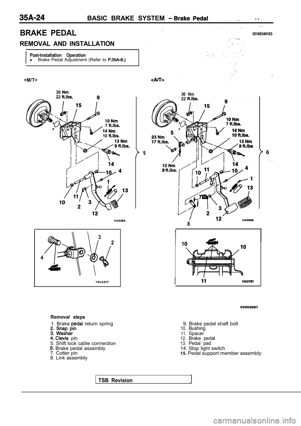
BRAKE PEDAL
REMOVAL AND INSTALLATION
Post-installation OperationlBrake Pedal Adjustment (Refer to
3022
7
10
‘6
3
2
4
Removal steps
1. Brake return spring
pin
5. Shift lock cable connection
Brake pedal assembly
7. Cotter pin
8. Link assembly
35100340103
30 Nm22
TSB Revision
8
9. Brake pedal shaft bolt10.Bushing
11.Spacer12.Brake pedal
13.Pedal pad
14. Stop light switch
15. Pedal support member assembly
6