Page 772 of 2103

E N G I N E EMISSION CONTROL Auto-cruise Control
No.
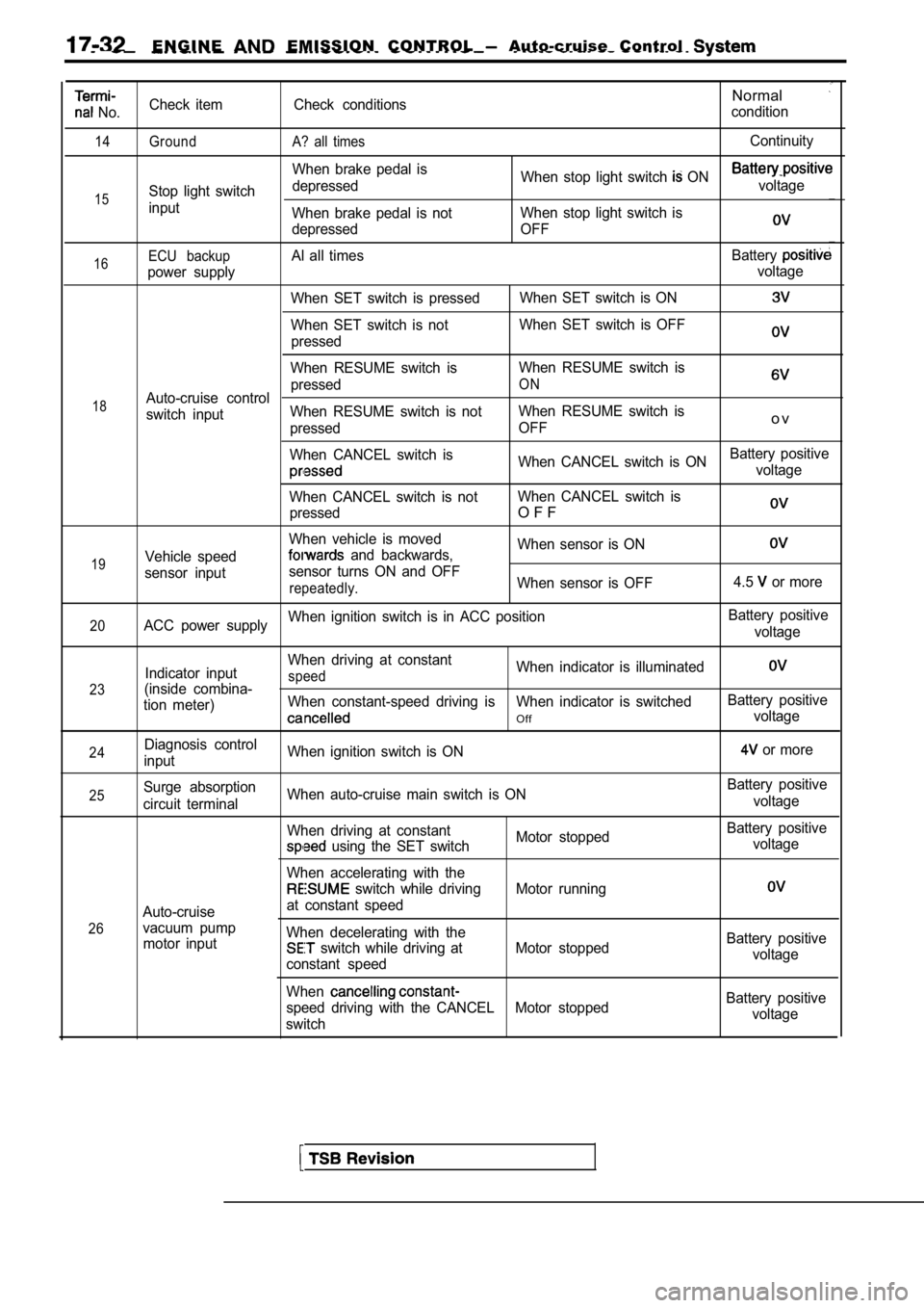
14
15
Check item
Ground
Stop light switch
inputCheck conditions
A? all times
When brake pedal is
depressed
When brake pedal is not
depressed
Normal
condition
Continuity
When stop light switch ON voltage
When stop light switch is
OFF
16
18
19ECU backupAl all times Battery
power supply voltage
When SET switch is pressed When SET switch is ON
When SET switch is notWhen SET switch is OFF
pressed
When RESUME switch is When RESUME switch is
pressed
ONAuto-cruise control
switch input When RESUME switch is not
When RESUME switch is
pressed OFF
o v
When CANCEL switch is
When CANCEL switch is ONBattery positivevoltage
When CANCEL switch is not When CANCEL switch is
pressed
O F F
When vehicle is moved When sensor is ON
Vehicle speed and backwards,
sensor input sensor turns ON and OFF
repeatedly.When sensor is OFF
4.5 or more
20ACC power supplyWhen ignition switch is in ACC position
Battery positive
voltage
23
24
Indicator input
(inside combina-
tion meter)
Diagnosis control
input When driving at constantspeedWhen indicator is illuminated
When constant-speed driving is When indicator is swi
tchedBattery positive
Offvoltage
When ignition switch is ON
or more
25
26Surge absorption
circuit terminal
Auto-cruise
vacuum pump motor input When auto-cruise main switch is ON
When driving at constant
Motor stopped
using the SET switch
When accelerating with the
switch while driving Motor running
at constant speed
When decelerating with the
switch while driving at Motor stopped
constant speed
When
speed driving with the CANCEL Motor stopped
switch Battery positive
voltage
Battery positive voltage
Battery positivevoltage
Battery positive voltage
Page 777 of 2103
ENGINE AND EMISSION CONTROL Auto-cruise Control System
CONTROL COMPONENT
STOP LIGHT SWITCH
MeasurementFor stop lightFor
conditionscircuitcontrol circuit
terminal No.
terminal
2314
When brake pedal
depressed.0
When brake pedal notdepressed.0 0
CLUTCH PEDAL POSITION SWITCH
Engine (Turbo) and Engine
Measurement conditions
When clutch pedal depressed.Terminal No.
12
0
When clutch pedal not depressed.
PARK/NEUTRAL POSITION SWITCH POSITION)
Engine (Turbo) and Engine>
Measurement Terminal No.Iconditions Engine (Turbo)7 8I
Engine
Selector lever is not at position
Selector lever is at
position 5
8
0
AUTO-CRUISE VACUUM PUMP (Turbo)
and
Engine>
1. Disconnect the vacuum hose from
vacuum
pump and connect a vacuum the vacuum pump.
2. Disconnect the electric vacuum pump connector.
TSB Revision
Page 902 of 2103
MANUAL TRANSAXLE OVERHAUL
Items
Transaxle
Backup light switch
Bearing retainer bolt
Bell housing cover mounting bolt
Center differential lock actuator mou
Center differential lock indicator
Center differential shift lever
Differential drive gear bolt
Input shaft lock nut
Interlock plate bolt
Intermediate gear lock nut
3324
33
24
Output gear mounting bolt
Poppet plug
Rear cover bolt
Rear cover bolt
Restrict ball
Reverse brake cone machine screw
Reverse idler gear shaft bolt
Reverse shift lever assembly
Select lever mounting bolt
Shift cable bracket mounting bolt
Speedometer sleeve bolt
Starter motor mounting bolt
Stopper bracket bolt
Transaxle case tightening bolt
Transaxle mount bracket mounting
Transaxle mounting bolt mm
Transaxle mounting bolt mm diamet
Transaxle mounting bolt
mm diamet
Transaxle switch
Revision
Page 907 of 2103
MANUALTRANSAXLE OVERHAUL Transaxle
TRANSAXLE
DISASSEMBLY AND REASSEMBLY
33N m24
19 Nm14I
36
27Nm
Disassembly steps
1. Bolt 2. Rear cover
3. Reverse brake cone
41 Wave spring 5. Machine screw
6. Backup light switch
7.Gasket8.Poppetplug
9.Poppet spring10.Poppetball
11.Bolt
Lubricate all internaloil
12. Speedometer. driven gear assembly 13. Air breather 14. Spring
15. Lock nut 16. Lock nut17. speed synchronizer assembly
18.
speed shift fork .
19.Synchronizer ring
20. speed gear21.Needle bearing22. speed intermediate gear
TSB Revision
Page 1020 of 2103

AUTOMATIC TRANSAXLE ENGINE
(TURBO) AND
ENGINE> Troubleshooting
scan
Inspection proce-
dure page if there an abnormality
is
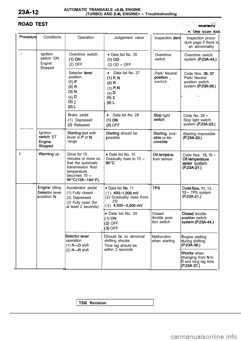
Conditions Operation
Inspection
1Ignition
switch: ON
Engine:
Stopped
gnition
ST
up
Idling
lever
osition:
Judgement value
Overdrive switch
system
Code Nos.
Park/ Neutral
position switch
system
Code No. 28
Stop light switch
system
Starting impossible
Code Nos. 16
system
12,
TPS system
throttle switch
ingine stalling
uring shifting
when
hanging from
to
and long lag time
Overdrive switch
(2) OFF
Data list No. 35
(2) OD OFF
Data list No. 37
(3)
(4)
Data list No. 28
ON
OFF
should be
possible Overdrive
switch
Selector
position
(4)
2
Park/ Neutral
s w i t c h
Brake pedal (1) Depressed
Released
light
pos-
or
I
ure sensor
test with
ever in
or
range
Drive for 15
minutes or more so
that the automatic
transmission fluid
temperature becomes 70 Data list No. 15
Gradually rises to 70
Accelerator pedal
(1) Fully closed
(2) Depressed
(3) Fully open (for
at least 2 seconds) Data list 11
( 1 )
(2) Gradually rises from
( 3 )
Data list No. 25
OFF
OFF
Closed
throttle posi-
tion switch
Should be no abnormal
shifting shocks
Time lag should be
within 2 seconds Malfunction
when starting
operation
(1)
shift
(2)
shift
TSB Revision
Page 1031 of 2103
AUTOMATIC TRANSAXLE ENGINE
(TURBO) AND
ENGINE>
[Comment]l Malfunction of stop light switch
If the stop light switch is ON far 15 minutes or mo re while driving at 3 km/h (2 more, l of connectorthere is a short circuit in the stop light switch a nd diagnostic trouble code No. 28 is output.
l of
SCAN TOOL DTCYes
Is TCL diagnostic trouble code No. 23 Stop light switch check (Refer toGROUP Brake Pedal.)
No NG
Repairl
OK
NG Repair
and stoplight switch.
OK
Check trouble
NG
Replace the TCM.
Page 1056 of 2103

AUTOMATIC TRANSAXLE
ENGINE (TURBO) AND ENGINE> Troubleshooting
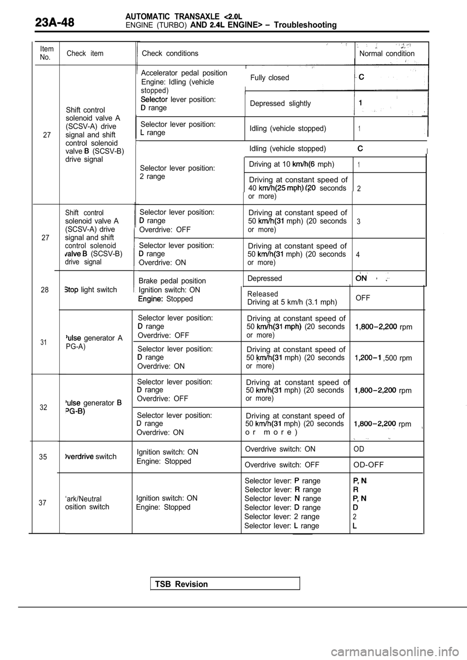
Item
No.
27
27
28
31
32
35
37 Check item
Shift control
solenoid valve A
(SCSV-A) drive
signal and shift
control solenoid
valve
(SCSV-B)
drive signal
Shift control
solenoid valve A
(SCSV-A) drive
signal and shift
control solenoid
(SCSV-B)
drive signal
Ignition switch: ON
Stopped
Selector lever position:
range
Overdrive: OFF
Selector lever position:
range
Overdrive: ON
Brake pedal position
light switch
Check conditionsNormal condition
Fully closed
Accelerator pedal position
Engine: Idling (vehicle
stopped)
lever position:
range Depressed slightly
Selector lever position:
range Idling (vehicle stopped)1
Idling (vehicle stopped)I
Selector lever position:
2 range Driving at 10 mph)1
Driving at constant speed of
40 seconds2or more)
Released
Driving at 5 km/h (3.1 mph)
Driving at constant speed of
50 mph) (20 seconds3
or more)
Driving at constant speed of
50 mph) (20 seconds4
or more)
Depressed ,
OFF
Selector lever position:
Driving at constant speed of
range 50 (20 seconds rpm
generator AOverdrive: OFFor more)
PG-A)
Selector lever position:Driving at constant speed of range 50 mph) (20 seconds ,500 rpm
Overdrive: ON
or more)
Selector lever position:Driving at constant speed of range 50 mph) (20 seconds rpm
generator Overdrive: OFFor more)
Selector lever position:Driving at constant speed of range50 mph) (20 seconds rpm
Overdrive: ONo r m o r e )
Ignition switch: ON Overdrive switch: ONOD switchEngine: Stopped
Overdrive switch: OFFOD-OFF
Selector lever: range
Selector lever: range
‘ark/NeutralIgnition switch: ON Selector lever: range
osition switchEngine: Stopped Selector lever: range
Selector lever: 2 range2
Selector lever: range
TSB Revision
Page 1057 of 2103

AUTOMATIC TRANSAXLE
ENGINE (TURBO) AND ENGINE> Troubleshooting
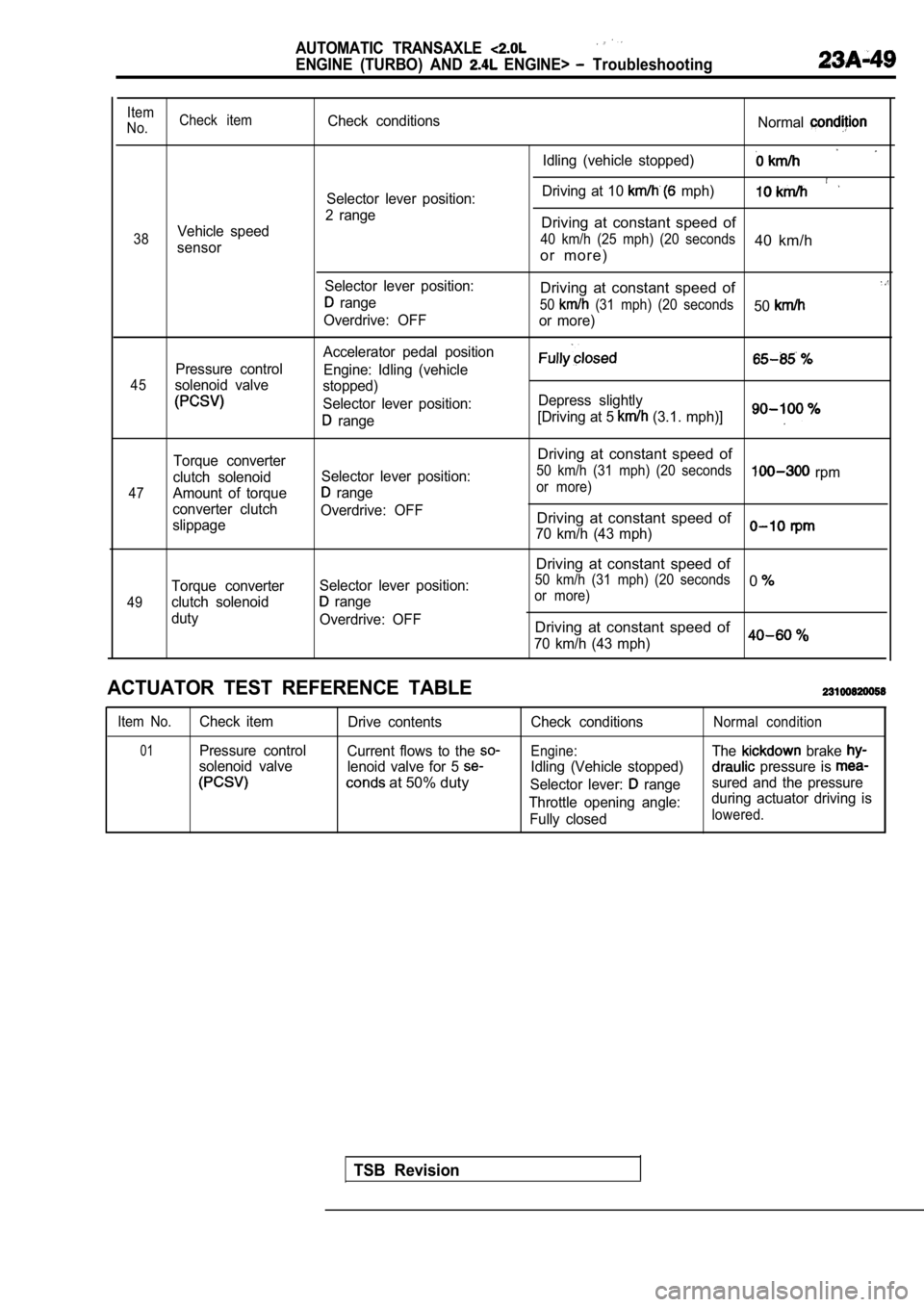
Item
No. Check itemCheck conditions
Normal
Idling (vehicle stopped)
Driving at 10 mph)Selector lever position:
2 range
Vehicle speedDriving at constant speed of
38 40 km/h (25 mph) (20 seconds40 km/hsensoro r m o r e )
Selector lever position:Driving at constant speed of range50 (31 mph) (20 seconds50Overdrive: OFF
or more)
Accelerator pedal position
Pressure control Engine: Idling (vehicle
45solenoid valvestopped)
Selector lever position: Depress slightly
range[Driving at 5 (3.1. mph)]
47
49
Torque converter
clutch solenoid
Amount of torque
converter clutch
slippage
Torque converter
clutch solenoid
duty Selector lever position:
range
Overdrive: OFF
Selector lever position:
range
Overdrive: OFF
Driving at constant speed of
50 km/h (31 mph) (20 seconds rpmor more)
Driving at constant speed of
70 km/h (43 mph)
Driving at constant speed of
50 km/h (31 mph) (20 seconds0or more)
Driving at constant speed of
70 km/h (43 mph)0
ACTUATOR TEST REFERENCE TABLE
Item No.Check item Drive contents
01Pressure controlCurrent flows to the
solenoid valve lenoid valve for 5
at 50% duty
Check conditions
Engine:
Idling (Vehicle stopped)
Selector lever:
range
Throttle opening angle: Fully closed
Normal condition
The brake
pressure is
sured and the pressure
during actuator driving is
lowered.
TSB Revision