1990 MITSUBISHI SPYDER jack points
[x] Cancel search: jack pointsPage 79 of 2103
ENGINE -‘Engine Assembly
COMPRESSOR
Disconnect the compressor connector and remove the
compressor from the compressor bracket
the hose
attached.
NOTE
Place the removed A/C compressor in a where it will
not be a hindrance when removing ‘and installing th e engine
assembly, and tie it with a cord:
Caution
Do not bend the joint the A/C hose and the
pipe by force.
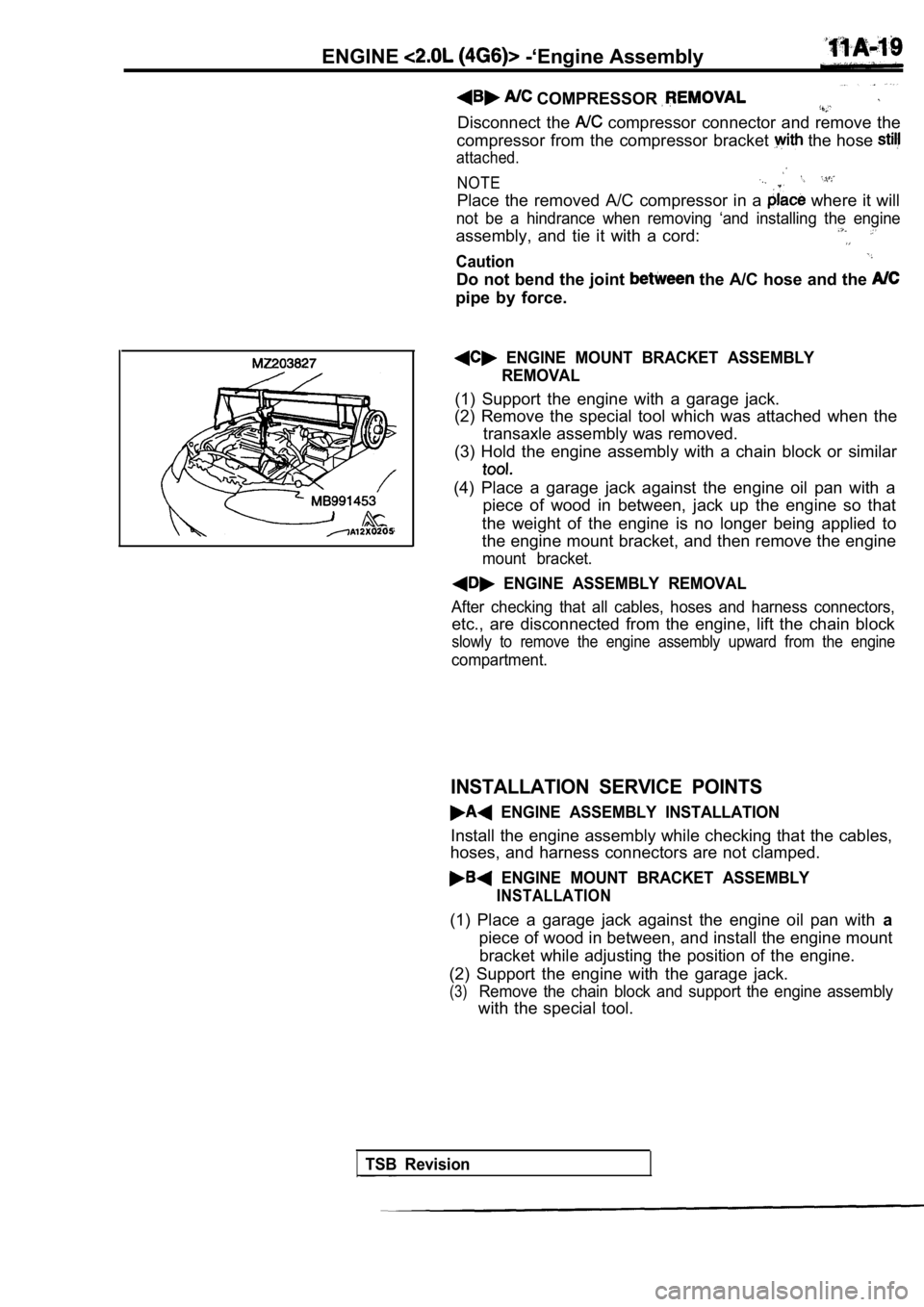
ENGINE MOUNT BRACKET ASSEMBLY
REMOVAL
(1) Support the engine with a garage jack.
(2) Remove the special tool which was attached when the
transaxle assembly was removed.
(3) Hold the engine assembly with a chain block or similar
(4) Place a garage jack against the engine oil pan with a
piece of wood in between, jack up the engine so tha t
the weight of the engine is no longer being applied to
the engine mount bracket, and then remove the engin e
mount bracket.
ENGINE ASSEMBLY REMOVAL
After checking that all cables, hoses and harness connectors,
etc., are disconnected from the engine, lift the chain block
slowly to remove the engine assembly upward from th e engine
compartment.
INSTALLATION SERVICE POINTS
ENGINE ASSEMBLY INSTALLATION
Install the engine assembly while checking that the cables,
hoses, and harness connectors are not clamped.
ENGINE MOUNT BRACKET ASSEMBLY
INSTALLATION
(1) Place a garage jack against the engine oil pan with a
piece of wood in between, and install the engine mo unt
bracket while adjusting the position of the engine.
(2) Support the engine with the garage jack.
(3)Remove the chain block and support the engine assem bly
with the special tool.
TSB Revision
Page 188 of 2103

ENGINE Enaine
Engine side
bracketEngine
Notch
INSTALLATION SERVICE POINTS
ENGINE ASSEMBLY INSTALLATION
Install the engine assembly while checking that the cables,
hoses, and harness connectors are not clamped.
ENGINE MOUNT BRACKET ASSEMBLY
INSTALLATION
(1) Place a garage jack against the engine oil pan with a
piece of wood in between, and install the engine mo unt
bracket while adjusting the position of the engine.
(2) Support the engine with the garage jack.
(3)Removethechain block and support the engine assembly
with the special tool.
(4) Align the notches on the
the
bracket with the arrow facing shown
direction. Then install the
HIGH-PRESSURE FUEL HOSE CONNECTION
When connecting the high-pressure fuel hose to the fuel rail,
apply a small amount of clean engine oil to the hose union,
and then insert, being careful not to damage the O- ring.
Caution
Do not let the engine oil get into the fuel rail.
TSB Revision
Page 192 of 2103
ENGINECamshaft and
554
.
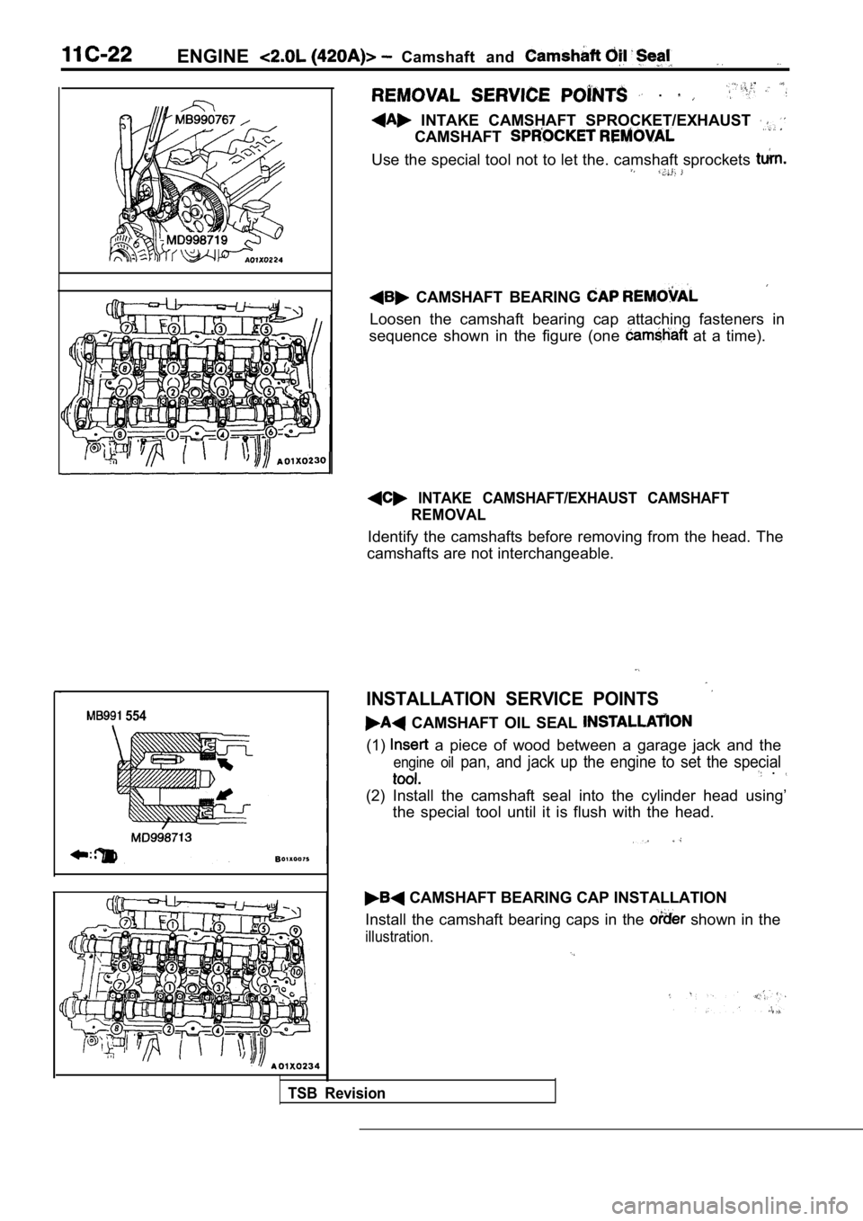
INTAKE CAMSHAFT SPROCKET/EXHAUST
CAMSHAFT
Use the special tool not to let the. camshaft sprockets
CAMSHAFT BEARING
Loosen the camshaft bearing cap attaching fasteners in
sequence shown in the figure (one
at a time).
INTAKE CAMSHAFT/EXHAUST CAMSHAFT REMOVAL
Identify the camshafts before removing from the hea d. The
camshafts are not interchangeable.
INSTALLATION SERVICE POINTS
CAMSHAFT OIL SEAL
(1) a piece of wood between a garage jack and the
engine oil pan, and jack up the engine to set the special .
(2) Install the camshaft seal into the cylinder hea d using’
the special tool until it is flush with the head.
CAMSHAFT BEARING CAP INSTALLATION
Install the camshaft bearing caps in the
shown in the
illustration.
TSB Revision
Page 205 of 2103
ENGINE Timing Belt
REMOVAL SERVICE POINTS
POWER STEERING OIL PUMP
Remove the power steering oil pump from the bracket with
the hose attached.
Place the removed power pump in a place where
it will not be a hindrance when removing and instal ling ‘the
timing belt, and tie it with a cord.
ENGINE MOUNT BRACKET ASSEMBLY REMOVAL
I
sprocket
pulley
Place a garage jack against the engine oil pan with a
of wood in between, jack up the engine so that weight
of the engine is no longer being applied to the eng ine mount
bracket, and then remove the mount bracket.
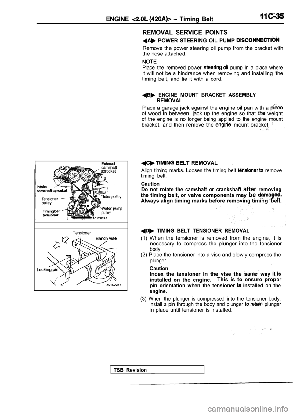
BELT REMOVAL.
Align timing marks. Loosen the timing belt remove
timing belt.
Caution Do not rotate the camshaft or crankshaft
afterremoving
the timing belt, or valve components may be
Always align timing marks before removing timing ‘b elt.
TIMING BELT TENSIONER REMOVAL
(1) When the tensioner is removed from the engine, it is
necessary to compress the plunger into the tensione r
body.
(2) Place the tensioner into a vise and slowly compress the
plunger.
Caution
Index the tensioner in the vise the way
installed on the engine.This is to ensure proper
pin orientation when the tensioner installed on the
engine.
(3) When the plunger is compressed into the tension er body,
install a pin through the body and plunger
plunger
in place until tensioner is installed.
Tensioner
TSB Revision
Page 286 of 2103
REMOVAL SERVICE POINTS
POWER STEERING PUMP REMOVAL
power steering pump from the bracket with the
hose attached.
NOTE
Place the removed power steering pump in a place wh ere
will not be a hindrance when removing and installing the
engine assembly, and tie it with a cord.
A/C COMPRESSOR REMOVAL
Disconnect the compressor connector and remove the
compressor from the compressor bracket with the hos e still
a t t a c h e d .
NOTE:
Place the removed A/C compressor in a place where i t will
not be
hindrance when removing and installing the engine
assembly, and tie it with a cord.
Do not bend the joint between hose and the A/C
pipe
force.
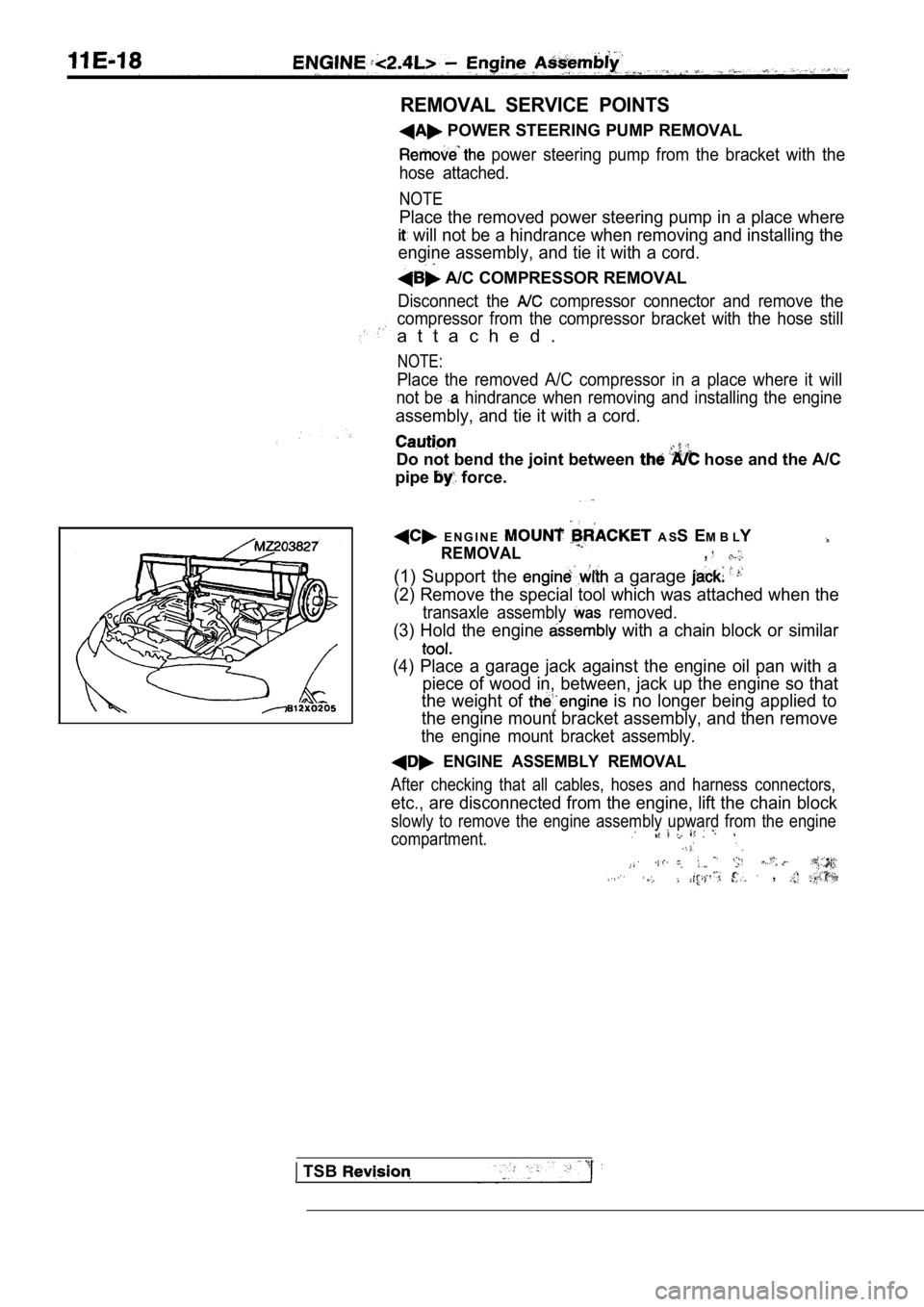
E N G I N E A S S E M B L Y
REMOVAL,
(1) Support the a garage
(2) Remove the special tool which was attached when the
transaxle assembly removed.
(3) Hold the engine with a chain block or similar
(4) Place a garage jack against the engine oil pan with a
piece of wood in, between, jack up the engine so th at
the weight of
is no longer being applied to
the engine mount bracket assembly, and then remove
the engine mount bracket assembly.
ENGINE ASSEMBLY REMOVAL
After checking that all cables, hoses and harness c onnectors,
etc., are disconnected from the engine, lift the chain block
slowly to remove the engine assembly upward from th e engine
compartment.
,
TSB
Page 872 of 2103
MANUAL TRANSAXLE
ENGINE AND ENGINE> Transaxle Assembly
I
Nut
ITransaxle
REMOVAL SERVICE POINTS
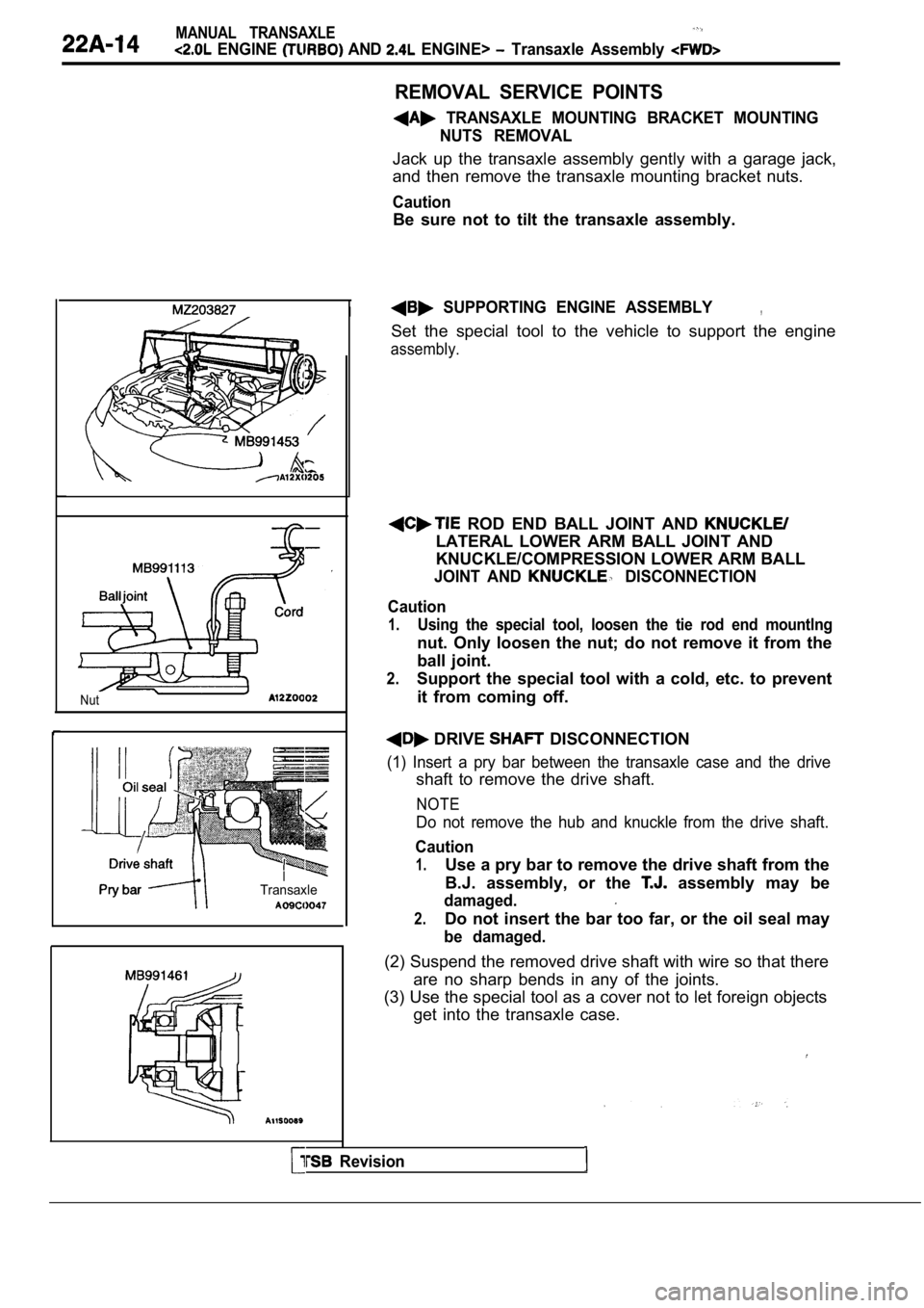
TRANSAXLE MOUNTING BRACKET MOUNTINGNUTS REMOVAL
Jack up the transaxle assembly gently with a garage jack,
and then remove the transaxle mounting bracket nuts .
Caution
Be sure not to tilt the transaxle assembly.
SUPPORTING ENGINE ASSEMBLY,
Set the special tool to the vehicle to support the engine
assembly.
ROD END BALL JOINT AND
LATERAL LOWER ARM BALL JOINT AND
KNUCKLE/COMPRESSION LOWER ARM BALL
JOINT AND DISCONNECTION
Caution
1.Using the special tool, loosen the tie rod end moun tlng
nut. Only loosen the nut; do not remove it from the
ball joint.
2.Support the special tool with a cold, etc. to prevent
it from coming off.
DRIVE DISCONNECTION
(1) Insert a pry bar between the transaxle case and the drive
shaft to remove the drive shaft.
NOTE
Do not remove the hub and knuckle from the drive sh aft.
Caution
1.Use a pry bar to remove the drive shaft from the
B.J. assembly, or the
assembly may be
damaged.
2.Do not insert the bar too far, or the oil seal may
be damaged.
(2) Suspend the removed drive shaft with wire so that there
are no sharp bends in any of the joints.
(3) Use the special tool as a cover not to let fore ign objects
get into the transaxle case.
Revision
Page 876 of 2103
MANUAL TRANSAXLE
ENGINE AND ENGINE> Transaxle Assembly
I -
Cord
I’ --
Nut
REMOVAL SERVICE POINTS
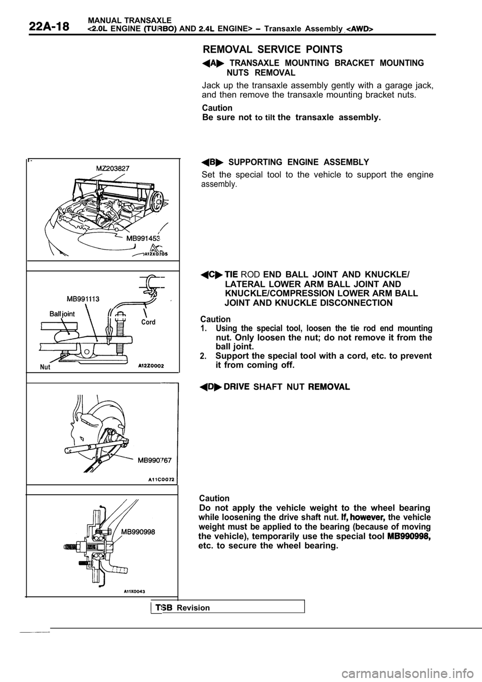
TRANSAXLE MOUNTING BRACKET MOUNTINGNUTS REMOVAL
Jack up the transaxle assembly gently with a garage jack,
and then remove the transaxle mounting bracket nuts .
Caution
Be sure not to tilt the transaxle assembly.
SUPPORTING ENGINE ASSEMBLY
Set the special tool to the vehicle to support the engine
assembly.
ROD END BALL JOINT AND KNUCKLE/
LATERAL LOWER ARM BALL JOINT AND
KNUCKLE/COMPRESSION LOWER ARM BALL
JOINT AND KNUCKLE DISCONNECTION
Caution
1.Using the special tool, loosen the tie rod end moun ting
nut. Only loosen the nut; do not remove it from the
ball joint.
2.Support the special tool with a cord, etc. to preve nt
it from coming off.
SHAFT NUT
Caution
Do not apply the vehicle weight to the wheel bearin g
while loosening the drive shaft nut. the vehicle
weight must be applied to the bearing (because of m oving
the vehicle), temporarily use the special tool
etc. to secure the wheel bearing.
I Revision
Page 888 of 2103
MANUAL TRANSAXLE
(NON-TURBO)> Transaxle Control
REMOVAL SERVICE POINTS
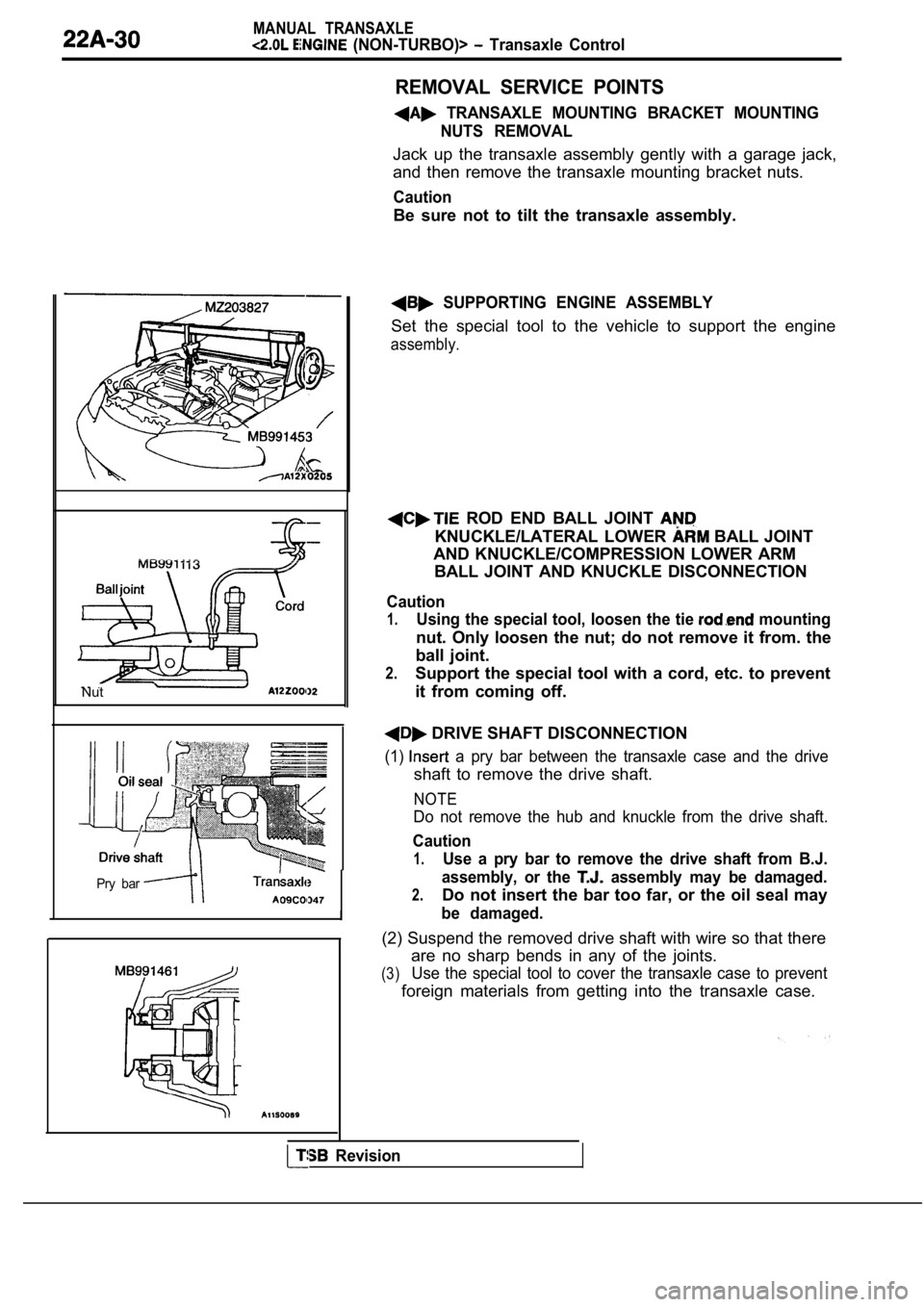
TRANSAXLE MOUNTING BRACKET MOUNTINGNUTS REMOVAL
Jack up the transaxle assembly gently with a garage jack,
and then remove the transaxle mounting bracket nuts .
Caution
Be sure not to tilt the transaxle assembly.
Nut
Pry bar
I
SUPPORTING ENGINE ASSEMBLY
Set the special tool to the vehicle to support the engine
assembly.
ROD END BALL JOINT
KNUCKLE/LATERAL LOWER BALL JOINT
AND KNUCKLE/COMPRESSION LOWER ARM BALL JOINT AND KNUCKLE DISCONNECTION
Caution
1.Using the special tool, loosen the tie mounting
nut. Only loosen the nut; do not remove it from. th e
ball joint.
2.Support the special tool with a cord, etc. to preve nt
it from coming off.
DRIVE SHAFT DISCONNECTION
(1) a pry bar between the transaxle case and the drive
shaft to remove the drive shaft.
NOTE
Do not remove the hub and knuckle from the drive sh aft.
Caution
1.Use a pry bar to remove the drive shaft from B.J.
2.
assembly, or the assembly may be damaged.
Do not insert the bar too far, or the oil seal may
be damaged.
(2) Suspend the removed drive shaft with wire so that there
(3)
are no sharp bends in any of the joints.
Use the special tool to cover the transaxle case to prevent
foreign materials from getting into the transaxle c ase.
Revision