Page 53 of 2103

GENERAL Maintenance
21 SYSTEM component
damage, to wiring,
harness, etc.)
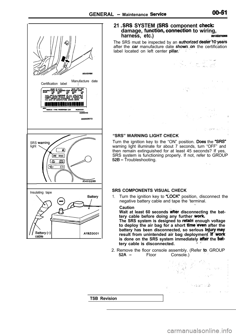
Certification labelManufacture dateI
SRSlight
Insulating tape
The SRS must be inspected by an
after the manufacture date the certification
label located on left center
,
“SRS” WARNING LIGHT CHECK,
Turn the ignition key to the “ON” position. the
warning light illuminate for about 7 seconds, turn “OFF” and
then remain extinguished for at least 45 seconds? I f yes,
SRS system is functioning properly. If not, refer t o GROUP
Troubleshooting.
SRS COMPONENTS VISUAL CHECK
1.Turn the ignition key to position, disconnect the
negative battery cable and tape the ‘terminal.
Caution
Wait at least 60 seconds
disconnecting the bat-
tery cable before doing any further
The SRS system is designed to enough voltage
to deploy the air bag for a short after the
battery has been disconnected, so serlous
result from unintended air bag deployment
is done on the SRS system immediately the
tery cable is disconnected. ,
2. Remove the floor console assembly. (Refer GROUP
Floor Console.)
TSB Revision
Page 867 of 2103

MANUAL TRANSAXLE
ENGINE (TURBO) AND ENGINE>
TRANSAXLE CONTROL
REMOVAL AND INSTALLATION
Caution: SRSBe careful not to subject the SRS-ECU to anyshocks during removal and installation of thetransaxle control cable and shift lever assembly.
Engine>
3.9 Nm
2.9
Engine (Turbo)>
9
9
9 bs.
.
NOTE Resin clip positionTransaxle control cable assemblyremoval steps
1. Air cleaner and air intake hose
assembly2. lever knob3. Center panel
4. Cupholder assembly
5. Floor console assembly
6. Shift lever cover
7. Console side cover
8. Nut 9. Clip (passenger compartment side)
10. Clip (transaxle side
11. Shift cable and select cable con- nection (passenger compartment
12. and select cable con-
nection (transaxle side)
13. Shift cable and select cable as-
sembly Shift lever
assembly removal steps
2 . S h i f t 3. Center. 4. assembly
5. Floor console assembly
6. Shift lever panel
7. Console side cover
9. Clip(passenger compartment side)
11. Shift cable and select cable con-nection (passenger compartmentside)14. Shift lever 15. Distance piece 16. Bushing
TSB Revision
Page 883 of 2103

MANUAL TRANSAXLE ENGINE (NON-TURBO)> Transaxle
TRANSAXLE CONTROL
REMOVAL AND INSTALLATION
Pre-removal and Post-installationOperationl Removal and Installation
3.9 Nm2.9
,I
Caution: SRS ,
Be careful not to the any
shocks during removal and of the
transaxle control cable and assembly.
12
l 11,
NOTE Resin clip
. .
Transaxle control cable assembly
removal steps
1. Air cleaner and air intake hose assembly
2. Battery tray and tray stay
3. Shift lever knob
4. Center panel5. Cup holder assembly
6. Floor console assembly
7. Shift lever cover
8. Console side cover
9. Nut
10. Clips (passenger compartment side)11. Clips (transaxle side)
14. Shift cable. select cable
assembly
Shift lever assembly steps
3. Shift lever knob
4. Center panel
5. Cup holder assembly
6. Floor console assembly ,
7. Shift lever panel
8. Console side cover’”
Clip side) 12. Shift cable and
12. Shift cable and select cable tion (passenger compartment
13. Shift cable and select cable con-
nection (transaxle
tion (passenger compartment
15. Shift lever assembly
16. Distance piece
TSB Revision 17. Bushing
Page 1101 of 2103
AUTOMATIC TRANSAXLE
ENGINE (TURBO) AND ENGINE>
REMOVAL AND INSTALLATION
Be not subject the any shocks
trol cable and shift lever assembly.
Engine>
8.8 Nm6.5
11 Nm
11 Nm8.3
118.3l
N m . .
NOTE Resin clip position11 Nm
8.3
Transaxle control cable assemblyremoval steps
1. Air cleaner and air intake hose sembly
2. Center panel
3. Cup holder assembly
4. Floor console assembly 5. Console side cover (L.H.)
6. Console side cover
(R.H.)
7. TCM bracket
8. Transaxle control module (TCM)
9. Nut10. Clip 11. Clip
12. Transaxle control cable connection
13. Nut14. Transaxle control cable assembly Selector lever assembly removal
steps
2. Center panel
3. Cup holder assembly
4. Floor console assembly 5. Console side cover (L.H.)
6. Console side cover (R.H.)
11. Clip
12. Transaxle control cable connection
15. Snap pin
16. Key interlock cable connection
17.
lock cable connection
18. Overdrive switch/position indicator
light connector19. Selector lever assembly
TSB Revision
Page 1106 of 2103

AUTOMATIC TRANSAXLE Automatic Transaxle Key Interlock
ENGINE (TURBO) AND ENGINE> and Shift Lock Mechanisms
23200120045
REMOVAL AND INSTALLATION
Caution:Be careful not to subject the SRS-ECU to any shocksduring removal and installation of the key interlockcable and shift lock cable.
567
I
- -
1 8 ’
NOTE(1) clip
(2) clipposition position
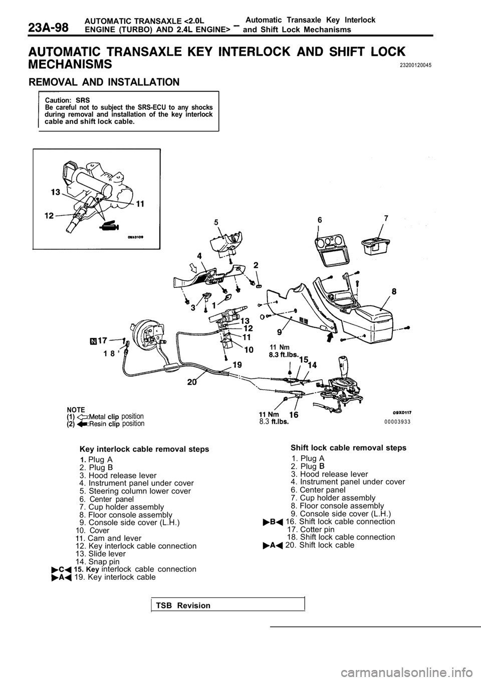
Key interlock cable removal steps
1. Plug A
2. Plug
3. Hood release lever
4. Instrument panel under cover
5. Steering column lower cover
6. Center panel7. Cup holder assembly
8. Floor console assembly9. Console side cover (L.H.)
10. Cover Cam and lever
12. Key interlock cable connection
13. Slide lever
14. Snap pin
15. Key interlock cable connection 19. Key interlock cable
11 Nm
8.30 0 0 0 3 9 3 3
Shift lock cable removal steps 1. Plug A
2. Plug
3. Hood release lever
4. Instrument panel under cover
6. Center panel
7. Cup holder assembly
8. Floor console assembly
9. Console side cover (L.H.)
16. Shift lock cable connection
17. Cotter pin
18. Shift lock cable connection
20. Shift lock cable
TSB Revision
Page 1193 of 2103
AUTOMATIC1 ENGINE (NON-TURBO)> Control
TRANSAXLE CONTROL
Be not to subject the to any shocks
trol cable and shift lever assembly.
4.9Nm
9.9 N m
8.3
i s - -11 Nm8.3
NOTE Resin clip position
Transaxle control cable assemblyremoval steps
1. Air cleaner and air intake hose as-sembly
2. Center panel
3. Cup holder assembly
4. Floor console assembly
5. Console side cover (L.H.)
6. Console side cover (R.H.)
7. Nut
8. Clip 9. Clip
10. Transaxle control cable connection
Nut12. EATX-ECM13. Transaxle control cable assembly
Selector lever assembly removalsteps
2. Center panel
3. Cup holder assembly
4. Floor console assembly
5. Console side cover (L.H.)
6. Console side cover (R.H.)
9. Clip
10. Transaxle controlcable connection14. Snap pin
15. Key interlock cable connection
16. Shift lock cable connection
17. Overdrive switch/position indicator
light connector
18. Selector lever assembly
TSB Revision
Page 1198 of 2103

AUTOMATIC TRANSAXLE
E N G I N E ( N O N - T U R B O ) >Automatic
Transaxle KeyInterlock and Shift LockMechanisms
AUTOMATIC TRANSAXLE KEY INTERLOCK AND SHIFT LOCK
MECHANISMS
Caution: SRSBe careful not to subject the SRS-ECU to any shocksduring removal and installation of the key interloc kcable and shift lock cable.
NOTE
567I
8 ’
clipposition position
Key
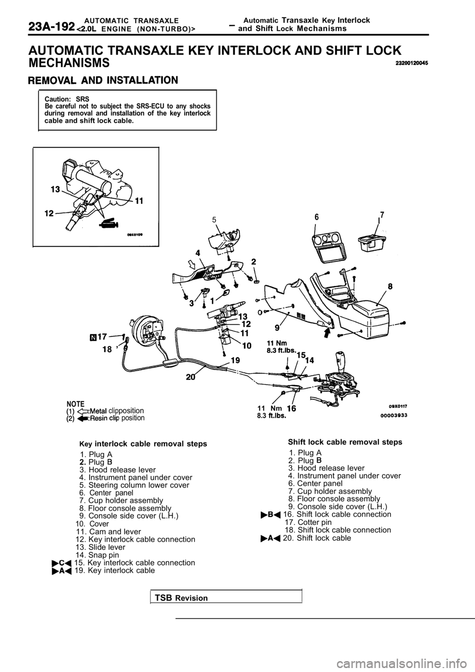
interlock cable removal steps
1. Plug A
2. Plug
3. Hood release lever
4. Instrument panel under cover
5. Steering column lower cover
6. Center panel7. Cup holder assembly
8. Floor console assembly
9. Console side cover (L.H.)
10. Cover11. Cam and lever
12. Key interlock cable connection
13. Slide lever
14. Snap pin
15. Key interlock cable connection 19. Key interlock cable 11 Nm
8.3
Shift lock cable removal steps
1. Plug A
2. Plug
3. Hood release lever
4. Instrument panel under cover 6. Center panel
7. Cup holder assembly
8. Floor console assembly
9. Console side cover (L.H.)
16. Shift lock cable connection
17. Cotter pin
18. Shift lock cable connection
20. Shift lock cable
TSB Revision
Page 1961 of 2103

INTERIOR Instrument Panel
REMOVAL AND INSTALLATION
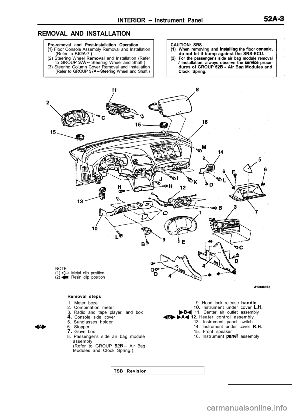
Pre-removal and Post-installation Operation Floor Console Assembly Removal and Installation(Refer to
(2) Steering Wheel Removaland Installation (Refer
to GROUP Steering Wheel and Shaft.)
(3) Steering Column Cover Removal and Installation
(Refer to GROUP Wheel and Shaft.)
CAUTION: SRS
(1) When removing and the floor do not let it bump against the SRS-ECU.(2)For the passenger’s side air bag module removal installation, always observe the proce-dures of GROUP Air Bag Modules andClock Spring.
14
5
NOTE
(1) Metal clip position
(2) Resin clip position
Removal steps
1. Meter bezel
2. Combination meter
3. Radio and tape player, and box
4. Console side cover
5. Sunglasses holder
6. Stopper 7. Glove box
8. Passenger’s side air bag module assembly(Refer to GROUP
Air Bag
Modules and Clock Spring.)
9. Hood lock release h a n d l e Instrument under cover 11. Center air outlet assembly 12. Heater control assembly
13. Instrument panel switch
14. Instrument under cover R . H .
15. Front speaker
16. Instrument
assembly
T S B R e v i s i o n