1990 MITSUBISHI SPYDER set clock
[x] Cancel search: set clockPage 124 of 2103
ENGINE OVERHAUL
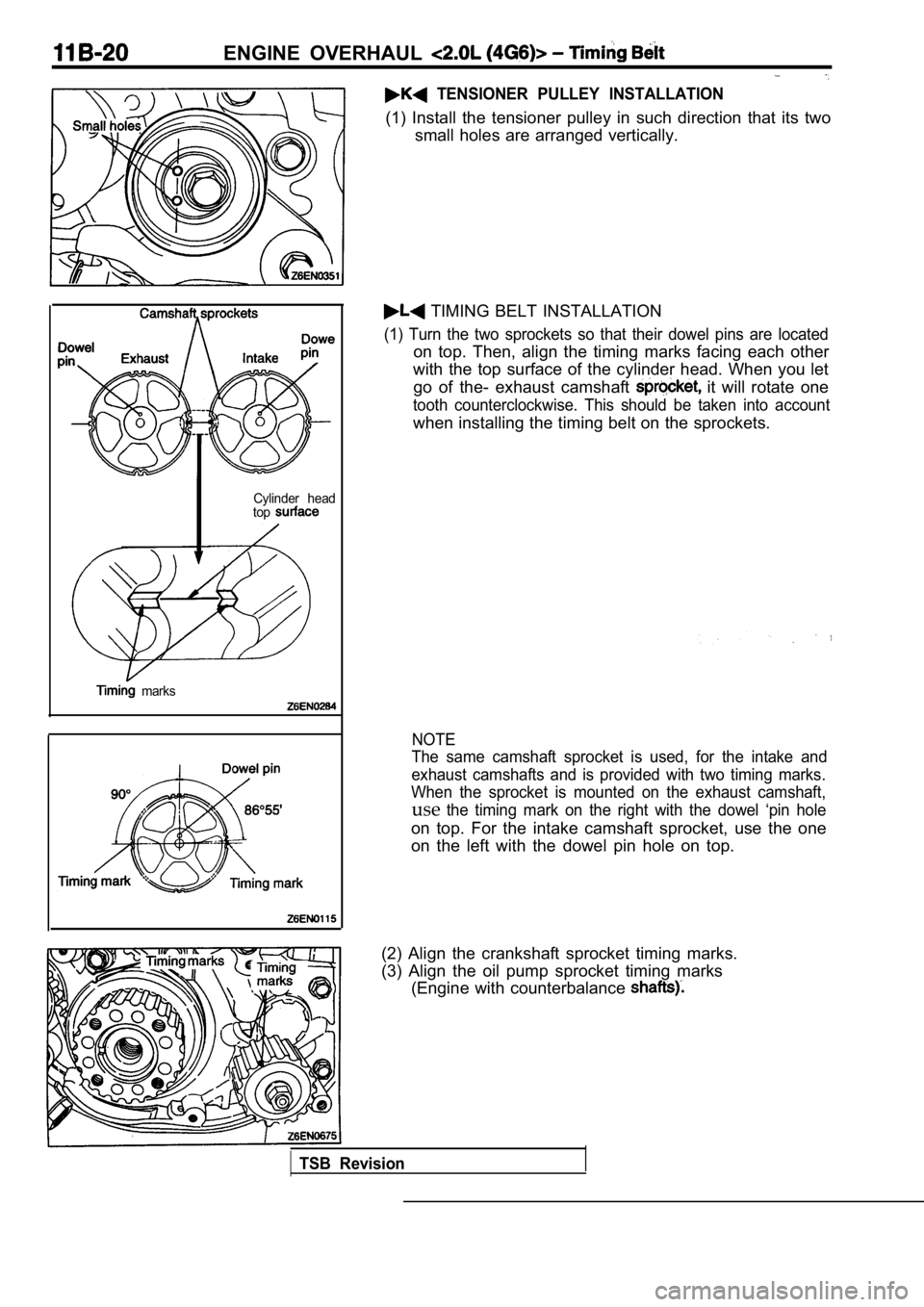
TENSIONER PULLEY INSTALLATION
(1) Install the tensioner pulley in such direction that its two
small holes are arranged vertically.
Cylinder head
top
marks
TIMING BELT INSTALLATION
(1) Turn the two sprockets so that their dowel pins are located
on top. Then, align the timing marks facing each ot her
with the top surface of the cylinder head. When you let
go of the- exhaust camshaft
it will rotate one
tooth counterclockwise. This should be taken into a ccount
when installing the timing belt on the sprockets.
NOTE
The same camshaft sprocket is used, for the intake and
exhaust camshafts and is provided with two timing m arks.
When the sprocket is mounted on the exhaust camshaf t,
usethe timing mark on the right with the dowel ‘pin hole
on top. For the intake camshaft sprocket, use the o ne
on the left with the dowel pin hole on top.
(2) Align the crankshaft sprocket timing marks.
(3) Align the oil pump sprocket timing marks (Engine with counterbalance
TSB Revision
Page 126 of 2103
ENGINE OVERHAUL Timing
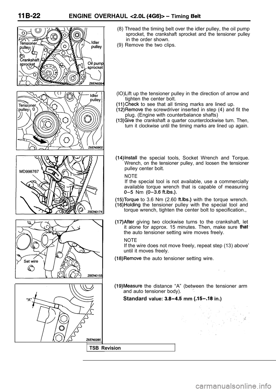
(8) Thread the timing belt over the idler pulley, the oil pump
sprocket, the crankshaft sprocket and the tensioner pulley
in the order shown.
(9) Remove the two clips.
(lO)Lift up the tensioner pulley in the direction o f arrow and
tighten the center bolt.
to see that all timing marks are lined up.
the screwdriver inserted in step (4) and fit the
plug. (Engine with counterbalance shafts)
the crankshaft a quarter counterclockwise turn. Th en,
turn it clockwise until the timing marks are lined up again.
the special tools, Socket Wrench and Torque.
Wrench, on the tensioner pulley, and loosen the ten sioner
pulley center bolt.
NOTE
If the special tool is not available, use a commercially
available torque wrench that is capable of measurin g
Nm
to 3.6 Nm (2.60 with the torque wrench.
the tensioner pulley with the special tool and
torque wrench, tighten the center bolt to specifica tion.,
giving two clockwise turns to the crankshaft, let
it alone for approx. 15 minutes. Then, make sure
the auto tensioner setting wire moves freely.
NOTE
If the wire does not move freely, repeat step (13) above’
until it moves freely.
the auto tensioner setting wire.
the distance “A” (between the tensioner arm
and auto tensioner body).
Standard value: mm in.)
TSB Revision
Page 304 of 2103
ENGINE
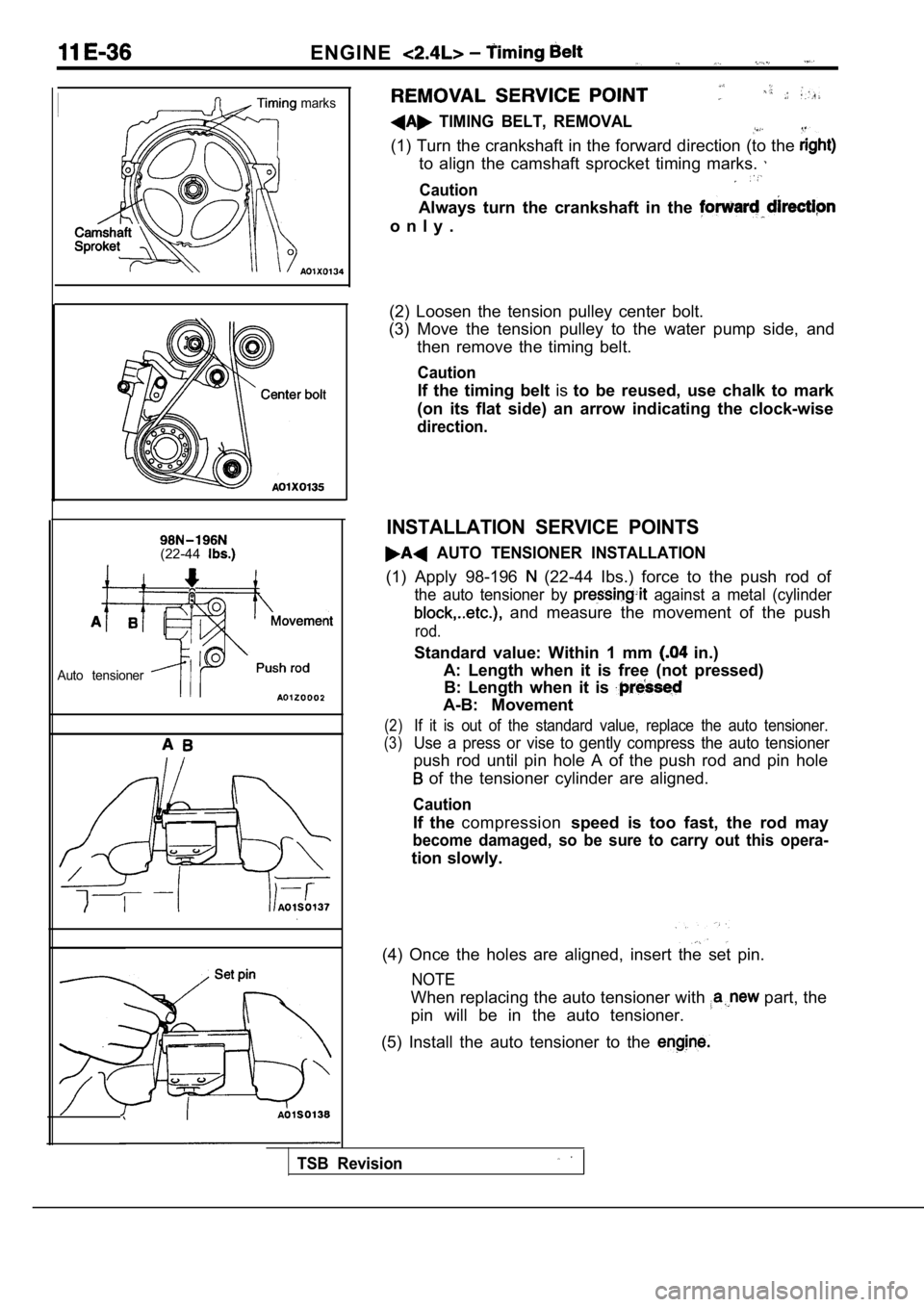
marks
(22-44
Auto tensioner
TIMING BELT, REMOVAL
(1) Turn the crankshaft in the forward direction (to the
to align the camshaft sprocket timing marks.
Caution
Always turn the crankshaft in the
o n l y .
(2) Loosen the tension pulley center bolt.
(3) Move the tension pulley to the water pump side, and
then remove the timing belt.
Caution
If the timing belt isto be reused, use chalk to mark
(on its flat side) an arrow indicating the clock-wi se
direction.
INSTALLATION SERVICE POINTS
AUTO TENSIONER INSTALLATION
(1) Apply 98-196 (22-44 Ibs.) force to the push rod of
the auto tensioner by against a metal (cylinder
and measure the movement of the push
rod.
Standard value: Within 1 mm in.)
A: Length when it is free (not pressed) B: Length when it is
A-B: Movement
(2)If it is out of the standard value, replace the aut o tensioner.
(3)Use a press or vise to gently compress the auto ten sioner
push rod until pin hole A of the push rod and pin hole
of the tensioner cylinder are aligned.
Caution
If the compression speed is too fast, the rod may
become damaged, so be sure to carry out this opera-
tion slowly.
(4) Once the holes are aligned, insert the set pin.
NOTE
When replacing the auto tensioner with part, the
pin will be in the auto tensioner.
(5) Install the auto tensioner to the
TSB Revision
Page 305 of 2103
E N G I N E Timing Belt
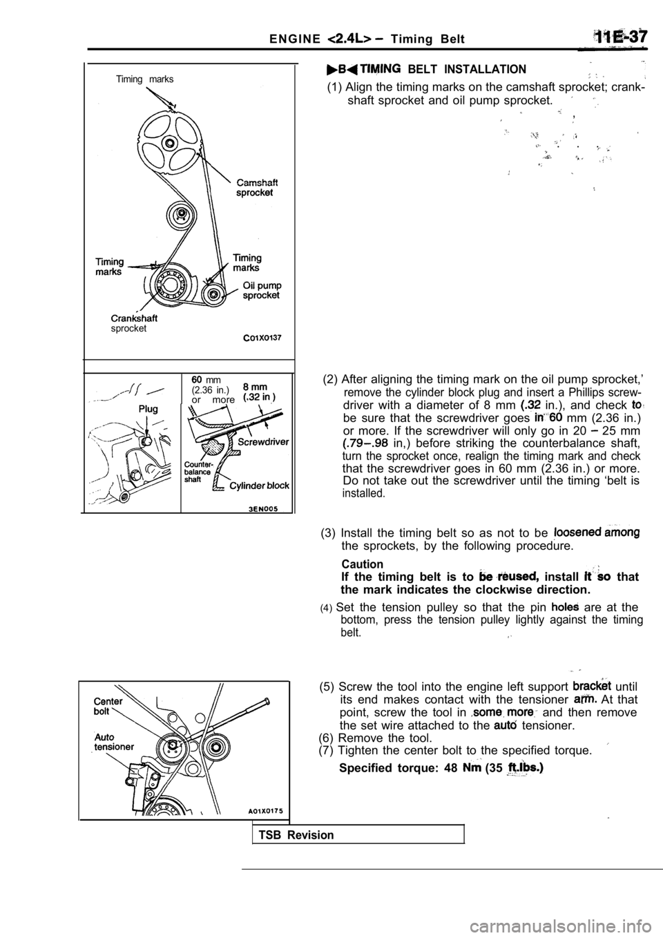
Timing marks
sprocket
mm
(2.36 in.)
or more .
BELT INSTALLATION
(1) Align the timing marks on the camshaft sprocket ; crank-
shaft sprocket and oil pump sprocket.
,
. . .
(2) After aligning the timing mark on the oil pump sprocket,’
remove the cylinder block plug and insert a Phillips screw-
driver with a diameter of 8 mm in.), and check
be sure that the screwdriver goes mm (2.36 in.)
or more. If the screwdriver will only go in 20
25 mm
in,) before striking the counterbalance shaft,
turn the sprocket once, realign the timing mark and check
that the screwdriver goes in 60 mm (2.36 in.) or mo re.
Do not take out the screwdriver until the timing ‘b elt is
installed.
(3) Install the timing belt so as not to be
the sprockets, by the following procedure.
Caution
If the timing belt is to install that
the mark indicates the clockwise direction.
(4) Set the tension pulley so that the pin
are at the
bottom, press the tension pulley lightly against th e timing
belt.
TSB Revision
(5) Screw the tool into the engine left support until
its end makes contact with the tensioner
At that
point, screw the tool in
and then remove
the set wire attached to the
tensioner.
(6) Remove the tool.
(7) Tighten the center bolt to the specified torque .
Specified torque: 48 (35
Page 330 of 2103
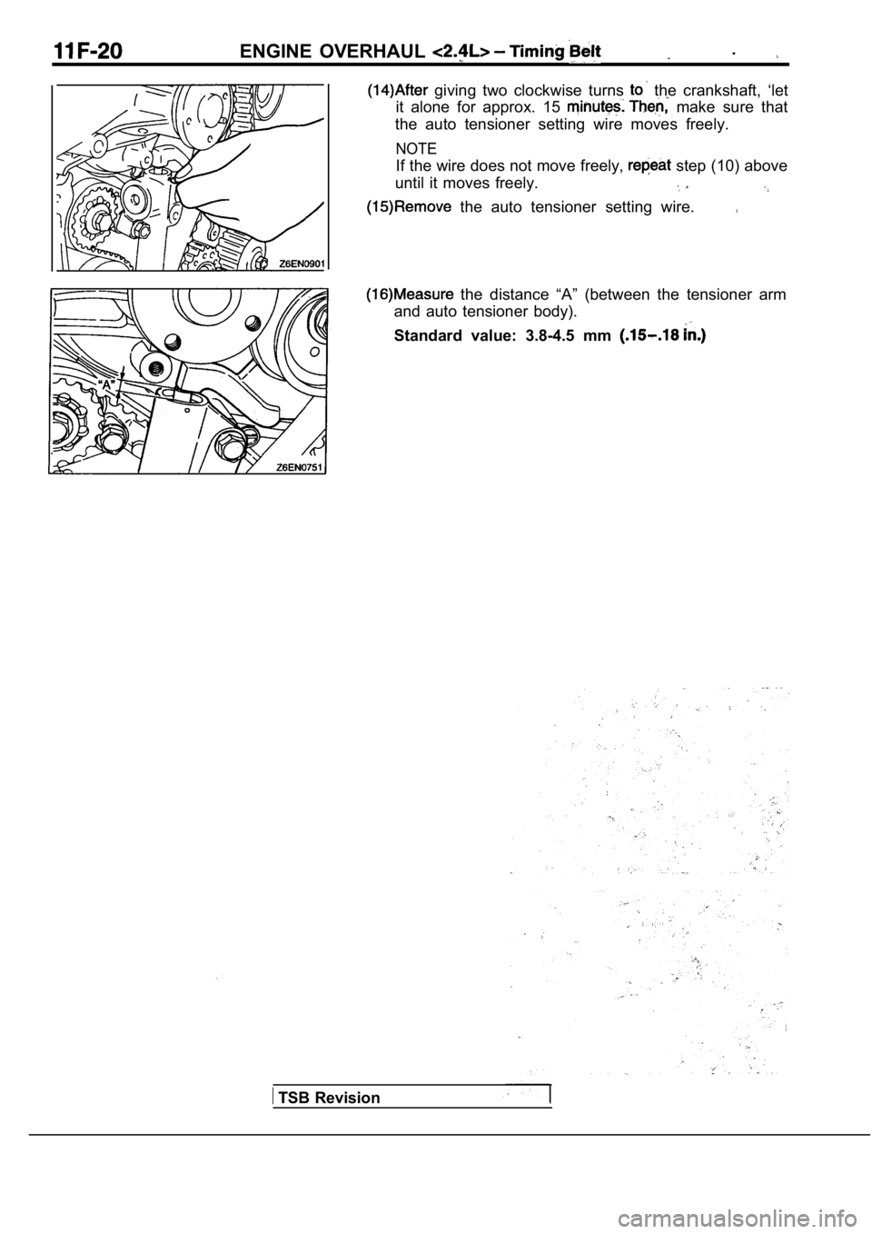
ENGINE OVERHAUL .
giving two clockwise turns the crankshaft, ‘let
it alone for approx. 15
make sure that
the auto tensioner setting wire moves freely.
NOTE
If the wire does not move freely, step (10) above
until it moves freely.
the auto tensioner setting wire.,
TSB Revision
the distance “A” (between the tensioner arm
and auto tensioner body).
Standard value: 3.8-4.5 mm
Page 394 of 2103
ENGINE (NON-TURBO)>
LEAK DETECTION PUMP MONITOR
Related diagnosis trouble codes (DTC)
l EVAP leak monitor small leak detected
l
EVAP leak monitor large leak detected
l
EVAP leak monitor pinched hose found
Operation
The leak detection assembly incorporates two primar y functions: it must detect a the
system and seal the evaporative system so the leak detection test can be run.. .
The’ primary components within the assembly are: A three port solenoid activates ‘both of the
functions listed above; a pump which contains a swi tch; two check valves and a spring/diaphragm, a’
canister vent valve (CVV) seal which contains a spr ing loaded vent seal valve.
Immediately after a cold start, between predetermin ed temperature thresholds limits, the three port
solenoid is briefly energized. This initializes the pump by drawing air into the pump cavity and also closes
the vent seal. During non test conditions the vent seal is held open by the pump diaphragm assembly
which pushes it open at the full travel position. The vent seal will remain closed while the pump is c ycling
due to the reed switch triggering of the three port solenoid that prevents the diaphragm assembly from
reaching full travel. After the brief initializatio n period, the solenoid is de-energized allowing atm ospheric
pressure to enter the pump cavity, thus permitting the spring to drive the diaphragm which forces air
out of the pump cavity and into the vent system. Wh en the solenoid is energized and de-energized,
the cycle is repeated creating flow in typical diaphragm pump fashion. The pump is controlled in 2 mod es:
Pump Mode: The pump is cycled at a fixed rate to achieve a rapid pressure build in order to shorten
the overall test length.
Test Mode: The solenoid is energized with a fixed d uration pulse. Subsequent fixed pulses occur
when the diaphragm reaches the Switch closure point .
The spring in the pump is set so that the system wi ll achieve an equalized pressure of about 7.5”
The cycle rate of pump strokes is quite rapid as the system begins to pump up to this pressure.
As the pressure
the cycle rate starts to drop off. If there is no leak in the system, the pump
would eventually stop pumping at the equalized pres sure. If there is a leak, it will continue to pump
at a rate representative of the flow characteristic of the size of the leak. From this information we can
determine if the leak is larger than the required d etection limit (currently set at
orifice by CARB).
If a leak is revealed during the leak test portion of the test, the test is terminated at the end of the
mode and no further system checks will be performed .
After passing the leak detection phase of the test, system pressure is maintained by turning on the
solenoid until the purge system is activated. Purg e activation in effect creates a leak. The cycle
rate is again interrogated and when it increases du e to the flow through the purge system, the leak
check portion of the diagnostic is complete.
The canister vent valve will unseal the system afte r completion of the test sequence as the pump
diaphragm assembly moves to the full travel positio n.
Evaporative system functionality will be verified b y using the stricter evap purge flow monitor. At an
appropriate warm idle the LDP will be energized to seal the canister vent. The purge flow will be clocked
up from some small value in an attempt to see a shi ft in the 02 control system. If fuel vapor, indicated
by a shift in the 02 control, is present the test i s passed. If not, it is assumed that the purge syst em
is not functioning in some respect. The LDP is agai n turned off and the test is ended.
TSB Revision
Page 755 of 2103
![MITSUBISHI SPYDER 1990 Service Repair Manual ENGINE AND EMISSION CONTROL Auto-cruise System
INSPECTION PROCEDURE 6
Auto-cruise control cannot be set.
[Comment]A malfunction of the auto-cruise control switch circuit may exist. MITSUBISHI SPYDER 1990 Service Repair Manual ENGINE AND EMISSION CONTROL Auto-cruise System
INSPECTION PROCEDURE 6
Auto-cruise control cannot be set.
[Comment]A malfunction of the auto-cruise control switch circuit may exist.](/manual-img/19/57345/w960_57345-754.png)
ENGINE AND EMISSION CONTROL Auto-cruise System
INSPECTION PROCEDURE 6
Auto-cruise control cannot be set.
[Comment]A malfunction of the auto-cruise control switch circuit may exist.
c a u s e,lMalfunction of the auto-cruise control switch
l M a l f u n c t i o n o f spring.
l Malfunction of the connector.
l
of
Auto-cruise control switch checkN G
Measure at clock spring connector
Disconnect the connector and mea-
* Voltage between terminal (3) and
and 40 Check trouble symptom.
Check the harness between the clockspring and ground. Repair, if necessary.
INSPECTION PROCEDURE 7
Hunting (repeated acceleration and deceleration) oc curs at the
set vehicle speed.
[Comment]
A malfunction of a speed sensor, the speed control servo, or the vacuum supply may be present.
For vehicle speed sensor checkFor input speed sensor or output speed sensor check(Refer to GROUP 54 Combination Meter.)
Speed control servo checkN G
Probable cause
lMalfunction the vehicle speed sensor lMalfunction of the input speed or outputspeed sensor l Malfunction of the l Malfunction of the vacuum supply.
l Malfunction of the PCM.
OK
Vacuum supply check (ReferNG
the PCM.
INSPECTION PROCEDURE 8
When the auto-cruise control main switch is ON, the switch
indicator on the instrument panel does not illumina te.
(However, auto-cruise control is normal.) Probable cause
[Comment]l
Malfunction of the auto-cruise control main
Blown bulb in auto-cruise control main switch.switch.
theau t o - c r u i s e c o n t r o l m a i n s w i t c h .
TSB Revision
Page 768 of 2103
![MITSUBISHI SPYDER 1990 Service Repair Manual 17-28ENGINE AND CONTROL Auto-cruise Control System
INSPECTION PROCEDURE 9
Auto-cruise control cannot be set. c a u s e
[Comment] Malfunction of the auto-cruise control main
A malfun MITSUBISHI SPYDER 1990 Service Repair Manual 17-28ENGINE AND CONTROL Auto-cruise Control System
INSPECTION PROCEDURE 9
Auto-cruise control cannot be set. c a u s e
[Comment] Malfunction of the auto-cruise control main
A malfun](/manual-img/19/57345/w960_57345-767.png)
17-28ENGINE AND CONTROL Auto-cruise Control System
INSPECTION PROCEDURE 9
Auto-cruise control cannot be set. c a u s e
[Comment] Malfunction of the auto-cruise control main
A malfunction of switches or that the fail-safe fun ction auto-cruise control may beswitch.
present.lMalfunction of the auto-cruise control l Malfunction of the clock l Malfunction of the harnesses or connectors.l of the clutch pedal position switch
lMalfunction of the park/neutral position switch
l Malfunction of control-EC@
Can the auto-cruise control communicate with the sc an
NoInspection for each trouble symptom.(Refer to inspection procedure No. 2 on
Yes
Is input switch inspection possible with the scan tool?
Yes
Inspectionfor trouble symptom.
(Refer to inspection procedure No. 3 on
Dose the input switch code or 27 remain output? Yes
No
Dose the input switch code or 26
No
Replace the auto-cruise control-ECU.
Yes lStop(Refer to inspection procedure No. 14 on lClutch pedal position switch or tion switch input circuit system [code
INSPECTION PROCEDURE 10
Hunting (repeated acceleration deceleration) occurs at the
set vehicle speed.
l Malfunction of the vehicle speed sensor.
A malfunction of vehicle speed sensor or incorrect vacuum in the auto-cruise vacuum pumplMalfunction of the auto-cruise l Malfunctionl Malfunction of the auto-cruise control-ECU.
Revision
Auto-cruise vacuum pump check (Refer to NG Replace
Actuator check (Refer to