1990 MITSUBISHI SPYDER set clock
[x] Cancel search: set clockPage 988 of 2103
MANUAL TRANSAXLE
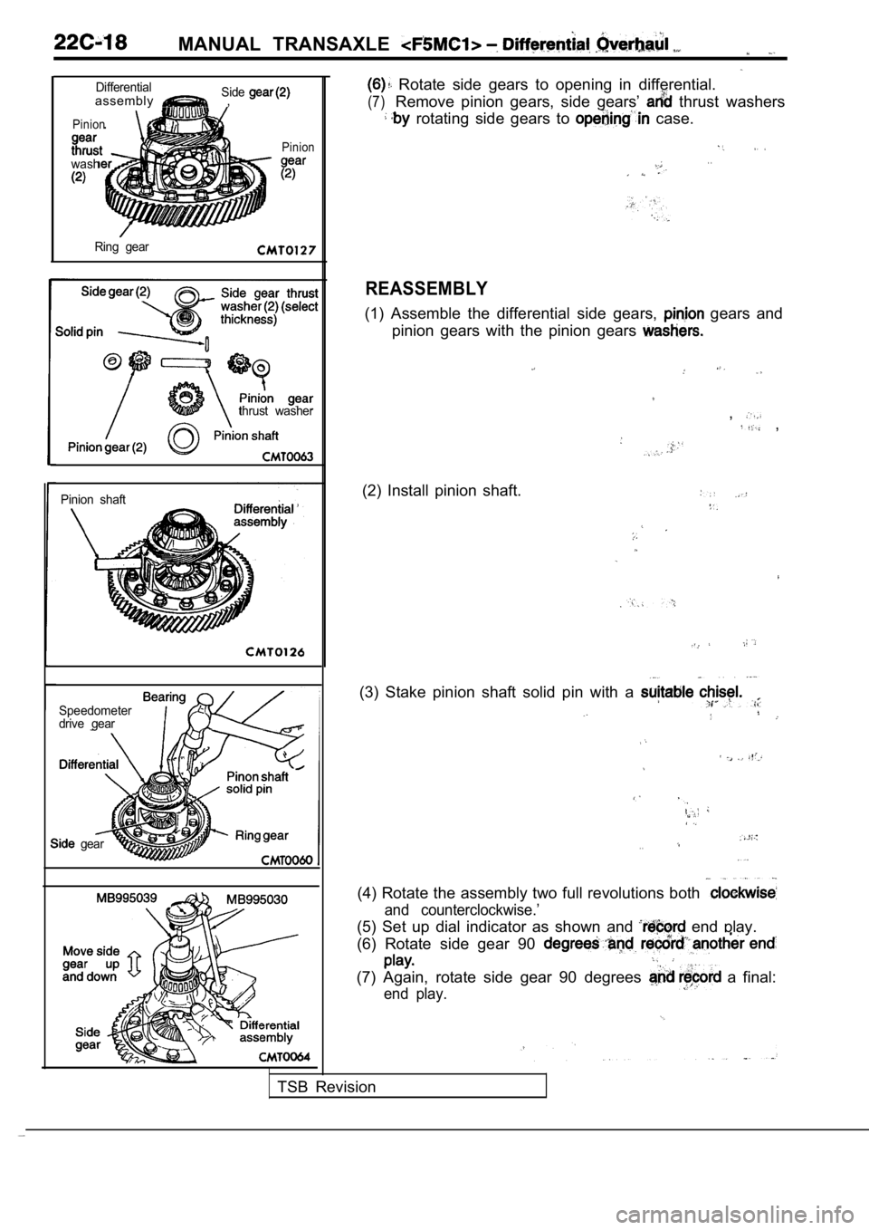
DifferentialassemblySide,
Pinion
wash
Pinion
Ring gear
thrust washer
Pinion shaft
Speedometer
drive gear
gear
Rotate side gears to opening in differential.
(7)Remove pinion gears, side gears’ thrust washers
rotating side gears to case.
. .
REASSEMBLY
(1) Assemble the differential side gears, gears and
pinion gears with the pinion gears
, ,
(2) Install pinion shaft.
(3) Stake pinion shaft solid pin with a
. .
(4) Rotate the assembly two full revolutions both
and counterclockwise.’
(5) Set up dial indicator as shown and end play.
(6) Rotate side gear 90
(7) Again, rotate side gear 90 degrees a final:
end play.
TSB Revision
Page 1005 of 2103
Differential Bearing
MANUAL TRANSAXLE Preload Adjustment
DIFFERENTIAL BEARING
ADJUSTMENT
True bearing turning torque readings can only be obtained
with the gear train removed from the case.
(1) Remove bearing cup and existing shim from clutc h
housing case.
(2) Press in new bearing cup into bell housing case (or use
a cup that has been ground down on the outer edge
for ease of measurement).
(3) Press in new bearing cup into gear case side.
(4) Lubricate differential bearings with SAE
engine
oil. Install differential assembly in transaxle gear case.
Install clutch bell housing over gear case.
and
torque case bolts to 29 Nm (21
(5) Position transaxle with bell housing facing dow n on work-
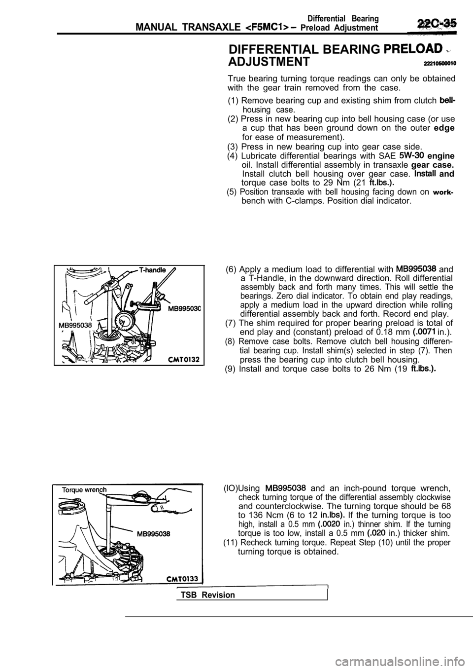
bench with C-clamps. Position dial indicator.
(6) Apply a medium load to differential with
and
a T-Handle, in the downward direction. Roll differe ntial
assembly back and forth many times. This will settl e the
bearings. Zero dial indicator. To obtain end play r eadings,
apply a medium load in the upward direction while r olling
differential assembly back and forth. Record end play.
(7) The shim required for proper bearing preload is total of
end play and (constant) preload of 0.18 mm
in.).
(8) Remove case bolts. Remove clutch bell housing d ifferen-
tial bearing cup. Install shim(s) selected in step (7). Then
press the bearing cup into clutch bell housing.
(9) Install and torque case bolts to 26 Nm (19
(lO)Using and an inch-pound torque wrench,
check turning torque of the differential assembly c lockwise
and counterclockwise. The turning torque should be 68
to 136 Ncm (6 to 12
If the turning torque is too
high, install a 0.5 mm in.) thinner shim. If the turning
torque is too low, install a 0.5 mm in.) thicker shim.
(11) Recheck turning torque. Repeat Step (10) until the proper
turning torque is obtained.
TSB Revision
Page 1009 of 2103
CONTENTS
AUTOMATIC TRANSAXLE
ENGINE (NON-TURBO)> . . . . . 115
AUTOMATIC TRANSAXLE KEY INTERLOCK
AND SHIFT LOCK MECHANISMS* . . . . . . . . 192
GENERAL INFORMATION
. . . . . . . . . . . . . . . . 115
LUBRICANTS. . . . . . . . . . . . . . . . . . . . . . . . . . . .117
ON-VEHICLE SERVICE . . . . . . . . . . . . . . . . . . . 159
Automatic Transaxle Control Component
Oil Temperature Sensor Continuity Check . . . . 160
Pinion Factor Writing Procedure After
TCM Replacement or Tire Size Change
. . . 159
Selector Level Operation Check . . . . . . . . . . . . . . ,166
Shift Lock Mechanism Check. . . . . . . . . . . . . . .
1 8 6
TCM Resetting Procedure . . . . . . . . . . . . .
..159
Torque Converter Stall Testing. . . . . . . . . . . . . .166
Transaxle Fluid Level Check . . . . . . . . . . .. . .159
Transaxle Fluid Replacement. . . . . . . . . . . . . . .
Transaxle Range Sensor Continuity . . .
Check. . . . . . . . . . . . . . . . . . . . . . . . . . . . . . . . . . . .163SERVICE SPECIFICATIONS.. . . .. . .Automatic Transaxle Control Component Layout
. . . . . . . . . . . . . . . . . . . . . . . . . . . . . . . . . . . . . . . . . . .
161SPECIAL TOOLS. . . . . . . . . . . . . . . . . . . . . . . . .117Clutch Air Pressure Tests . . . . . . . . . . . . . . . . . . .168
Fluid Leakage-Torque Converter Housing Area
Check. . . . . . . . . . . . . . . . . . . . . . . . . . . . . . . . . . . .169
Hydraulic Pressure Tests. . . . . . . . . . . . . . . . . . .169
Hydraulic Circuit. . . . . . . . . . . . . . . . . . . . . . . . . . .173
TRANSAXLE ASSEMBLY. . . . . . . . . . . . . . . .
TRANSAXLE CONTROL*. . . . . . . . . . . . . . . . .187
Selector Lever Assembly. . . . . . . . . . . . . . . . . . .189
Key Interlock Mechanism Check . . . . . . . . . . .
. 186CONTINUED ON NEXT PAGE
WARNINGS REGARDING SERVICING OF SUPPLEMENTAL EQUIPPED VEHICLES
WARNING! (1) Improper service or maintenance of any componen t of the
or any component, can lead to personal
injuryordeath inadvertent the inoperative).
(2) Service or maintenance of any component or SRS-related component must be perform ed only at an authorized
MITSUBISHI dealer.
(3)MITSUBISHI dealer personnel must thoroughly review this manual, and especially its GROUP Supplemental Re-
straint System (SRS) and GROUP 00 -Maintenance Serv ice before beginning any service or maintenance of any com-
ponent of the
or any component.
NOTEThe SRS includes the following components: SRS-ECU, SRS warning light, air bag module, clockspring and inte rconnecting wiring.Other SRS-related components (that may have to be removed/installed in connection with SRS service or maintenance) are indi-cated in the table of contents by an asterisk
Page 1622 of 2103
34-6REAR SUSPENSION Service
REAR WHEEL
ADJUSTMENT,Measure. wheel alignment with
ground.
The rear suspension and be serviced to the
normal condition prior to wheel alignment.
. .
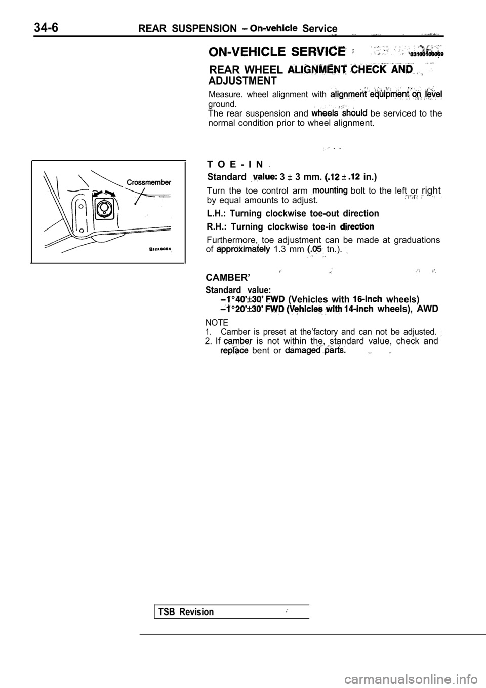
T O E - I N
Standard 3 3 mm. in.)
Turn the toe control arm bolt to the left or right
by equal amounts to adjust..
L.H.: Turning clockwise toe-out direction
R.H.: Turning clockwise toe-in
Furthermore, toe adjustment can be made at graduati ons
of
1.3 mm tn.).
CAMBER’
Standard value:
(Vehicles with wheels)
wheels), AWD
NOTE
1.Camber is preset at the’factory and can not be adju sted.
2. If is not within the, standard value, check and
bent or
TSB Revision
Page 1804 of 2103
STEERING Power Steering Gear Box
Bellows band
Concave
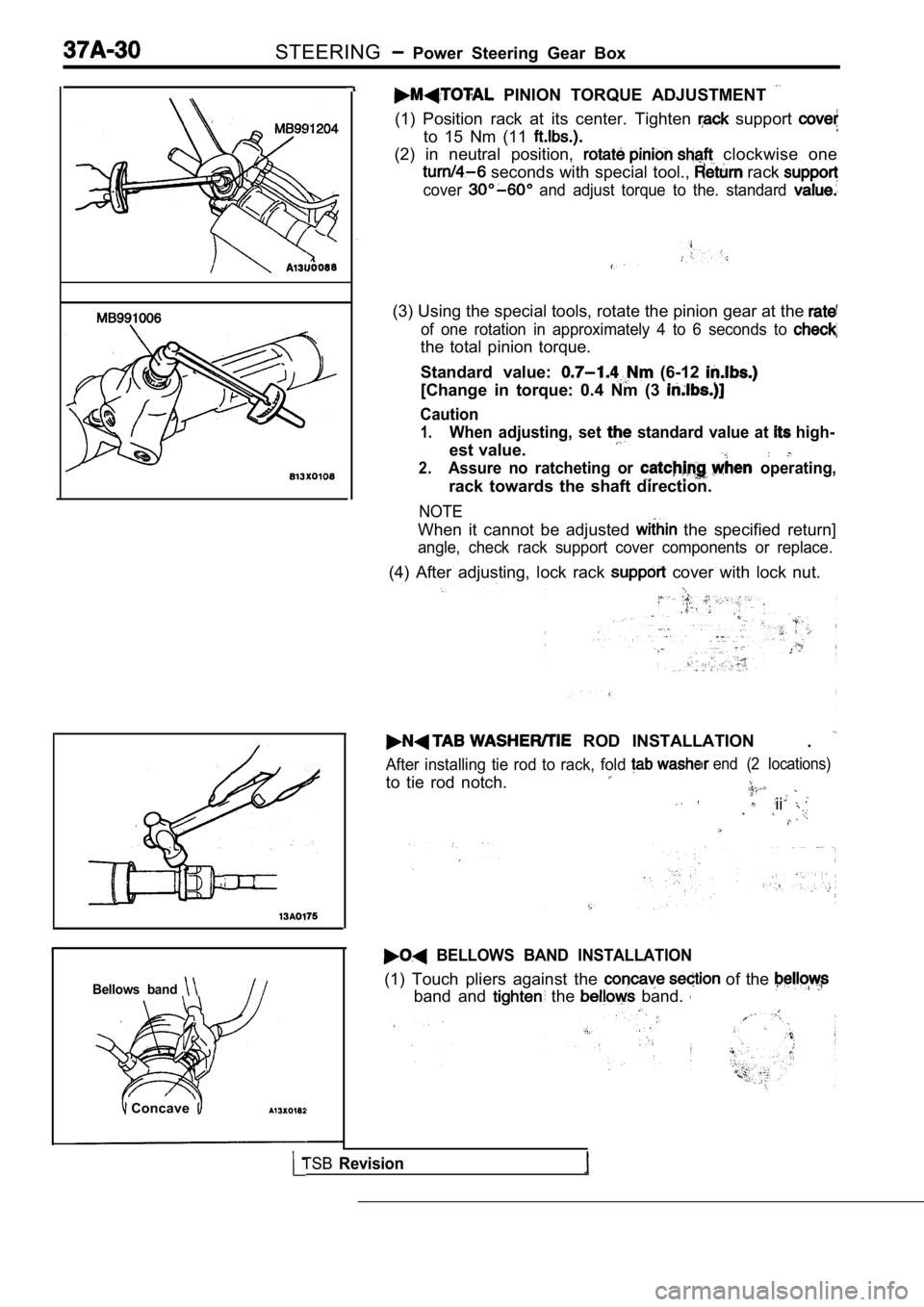
PINION TORQUE ADJUSTMENT
(1) Position rack at its center. Tighten support
to 15 Nm (11
(2) in neutral position, clockwise one
seconds with special tool., rack
cover and adjust torque to the. standard
(3) Using the special tools, rotate the pinion gear at the
of one rotation in approximately 4 to 6 seconds to
the total pinion torque.
Standard value:
(6-12
[Change in torque: 0.4 Nm (3
Caution
1.When adjusting, set standard value at high-
est value.
2.Assure no ratcheting or operating,
rack towards the shaft direction.
NOTE
When it cannot be adjusted the specified return]
angle, check rack support cover components or repla ce.
(4) After adjusting, lock rack cover with lock nut.
ROD INSTALLATION
.
After installing tie rod to rack, fold
to tie rod notch.
end (2 locations)
ii
BELLOWS BAND INSTALLATION
(1) Touch pliers against the of the
band and the band.
TSBRevision
Page 2030 of 2103
SRS Air Bag Modules and Clock Spring
AIR BAG MODULES AND CLOCK SPRING52400240022
Caution
1.Never attempt to disassemble or repair the
air bag module or clock spring. If faulty,
replace it.
2. Do not drop the air bag module or clockspring or allow contact with water, grease
or oil. Replace it if a dent, cracks,
deformation or rust are detected.
3. The air bag modules should be stored on
a flat surface and placed so that the pad
surface is facing upward. Do not place anything on top of
bag
modules.
4.
Do not expose the air module to
temperature over
5.After deployment of an air bag, replace the
clock spring.
6. Wear gloves and safety goggles
handling an air bag that has
7.An undeployed air bag module should only
be disposed of in accordance with the
specified procedures. (Refer to
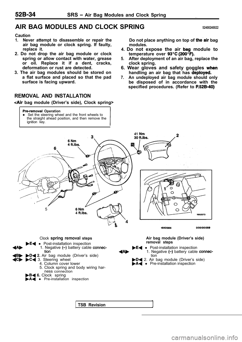
REMOVAL AND INSTALLATION
bag module (Driver’s side), Clock spring>
Operationl Set the steering wheel and the front wheels to
the straight ahead position, and then remove the
ignition key.
41
1. Negative battery cable l Post-installation inspection
2. Air bag module (Driver’s side) 1. Negative battery cable tion
3. Steering wheel
4. Column cover lower 2. Air bag module (Driver’s side)
5. Clock spring and body wiring har- l Pre-installation inspection
ness connection
6. Clock spring l Pre-installation inspection
TSB Revision
,
54
4
Clockspring removal steps
l Post-installation inspection Air bag module (Driver’s side)removal steps