1990 MITSUBISHI SPYDER stop start
[x] Cancel search: stop startPage 44 of 2103
GENERALMaintenanceService
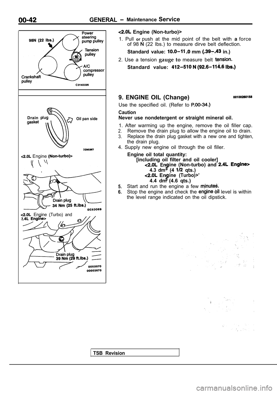
Drain
Oil pan side
Engine
Engine (Turbo) and
TSB Revision
Engine (Non-turbo)>
1. Pull orpush at the mid point of the belt with aforce
of 98
(22 Ibs.) to measure dirve belt deflection.
Standard value:
mm in.)
2. Use a tension gauge to measure belt
Standard value:
9. ENGINE OIL (Change)
Use the specified oil. (Refer to
Caution
Never use nondetergent or straight mineral oil.
1. After warming up the engine, remove the oil fill er cap.
2.Remove the drain plug to allow the engine oil to drain.
3.Replace the drain plug gasket with a new one and ti ghten,
the drain plug.
4. Supply new engine oil through the oil filler.
Engine oil total quantity:[including oil filter and oil cooler]
Enine (Non-turbo) and
4.3 dm(4 qts.)
Enine (Turbo)>’
4.4 dm (4.6 qts.)
Start and run the engine a few
Stop the engine and check the level is within
the level range indicated on the oil dipstick.
5.
6.
Page 46 of 2103
GENERAL
Oil level
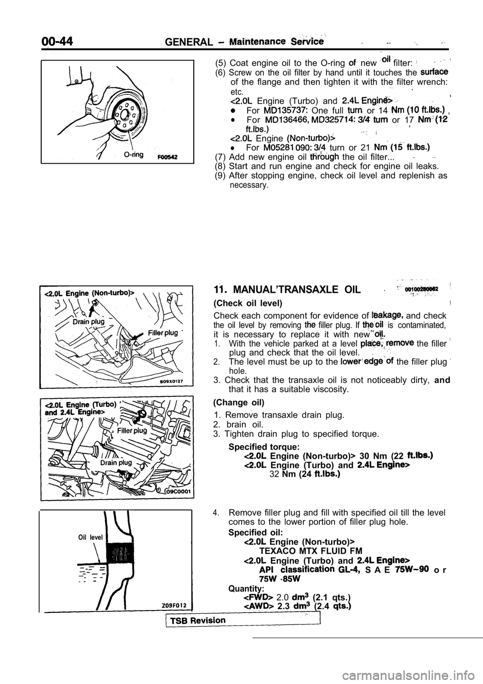
(5) Coat engine oil to the O-ring new filter:
(6) Screw on the oil filter by hand until it touches the
of the flange and then tighten it with the filter w rench:. . .etc..
Engine (Turbo) and
For One full or 14 ,
lFor or 17 ,
Engine
lFor turn or 21
(7) Add new engine oil the oil filter...
(8) Start and run engine and check for engine oil l eaks.
(9) After stopping engine, check oil level and repl enish as
necessary.
MANUAL’TRANSAXLE OIL
(Check oil level)
Check each component for evidence of and check
the oil level by removing filler plug. If is contaminated,
it is necessary to replace it with new
1.With the vehicle parked at a level the filler
plug and check that the oil level..
2.The level must be up to the the filler plug
hole.
3. Check that the transaxle oil is not noticeably d irty, and
that it has a suitable viscosity.
(Change oil) 1. Remove transaxle drain plug.
2. brain oil.
3. Tighten drain plug to specified torque.
Specified torque:
Engine (Non-turbo)> 30 Nm (22
Engine (Turbo) and
32Nm (24
4.Remove filler plug and fill with specified oil till the level
comes to the lower portion of filler plug hole.
Specified oil:
Engine (Non-turbo)>
TEXACO MTX FLUID FM
Engine (Turbo) and
S A E o r
Quantity:
2.0 (2.1 qts.)
2.3 (2.4
Page 51 of 2103
GENERAL Maintenance
a
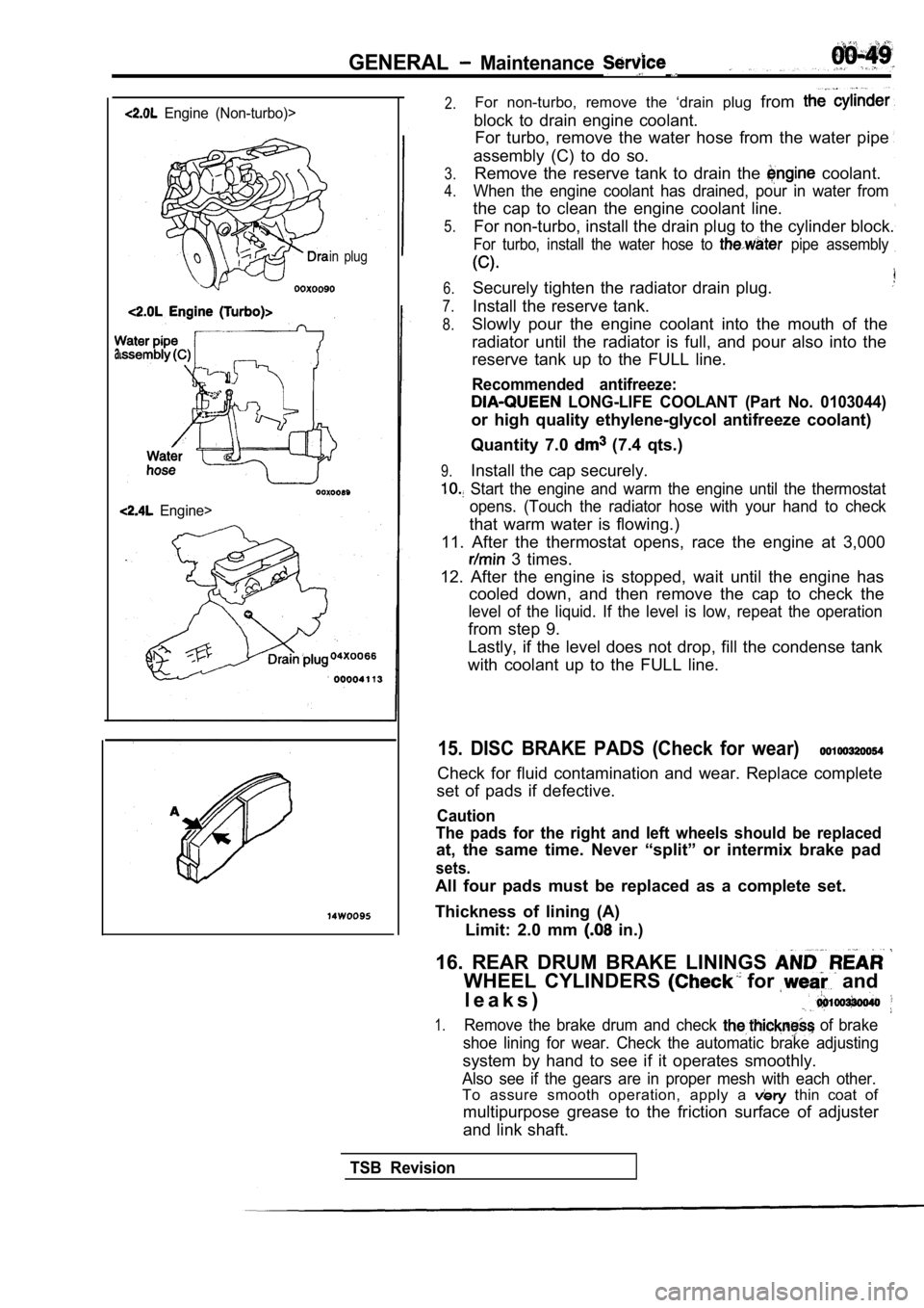
Engine (Non-turbo)>
in plug
Engine>
2.For non-turbo, remove the ‘drain plug from
block to drain engine coolant.
For turbo, remove the water hose from the water pip e
assembly (C) to do so.
3.
4.
5.Remove the reserve tank to drain the coolant.
When the engine coolant has drained, pour in water from
the cap to clean the engine coolant line.
For non-turbo, install the drain plug to the cylind er block.
For turbo, install the water hose to pipe assembly
6.
7.
8.
Securely tighten the radiator drain plug.
Install the reserve tank.
9.
Slowly pour the engine coolant into the mouth of th e
radiator until the radiator is full, and pour also into the
reserve tank up to the FULL line.
Recommended antifreeze:
LONG-LIFE COOLANT (Part No. 0103044)
or high quality ethylene-glycol antifreeze coolant)
Quantity 7.0
(7.4 qts.)
Install the cap securely.
Start the engine and warm the engine until the the rmostat
opens. (Touch the radiator hose with your hand to c heck
that warm water is flowing.)
11. After the thermostat opens, race the engine at 3,000
3 times.
12. After the engine is stopped, wait until the eng ine has
cooled down, and then remove the cap to check the
level of the liquid. If the level is low, repeat th e operation
from step 9.
Lastly, if the level does not drop, fill the conden se tank
with coolant up to the FULL line.
15. DISC BRAKE PADS (Check for wear)
Check for fluid contamination and wear. Replace com plete
set of pads if defective.
Caution
The pads for the right and left wheels should be re placed
at, the same time. Never “split” or intermix brake pad
sets.
All four pads must be replaced as a complete set.
Thickness of lining (A) Limit: 2.0 mm
in.)
16. REAR DRUM BRAKE LININGS
WHEEL CYLINDERS for and
l e a k s )
1.Remove the brake drum and check of brake
shoe lining for wear. Check the automatic brake adj usting
system by hand to see if it operates smoothly.
Also see if the gears are in proper mesh with each other.
To assure smooth operation, apply a thin coat of
multipurpose grease to the friction surface of adju ster
and link shaft.
TSB Revision
Page 74 of 2103
ENGINE On-vehicle Service
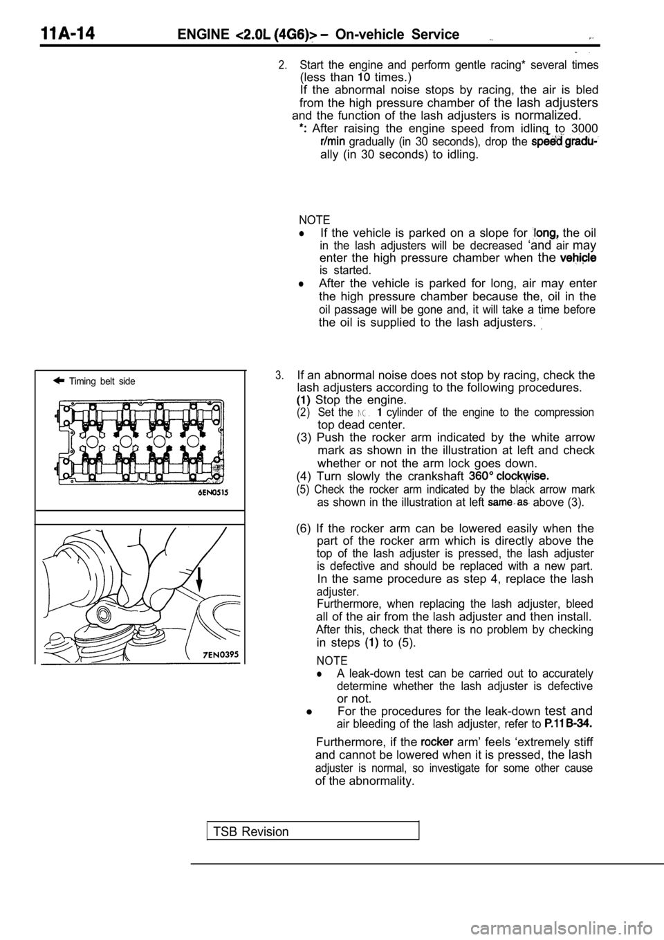
Timing belt side
.
2.Start the engine and perform gentle racing* several times
(less than times.)
If the abnormal noise stops by racing, the air is b led
from the high pressure chamber of the lash adjusters
and the function of the lash adjusters is normalized.
After raising the engine speed from idling to 3000
gradually (in 30 seconds), drop the
ally (in 30 seconds) to idling.
NOTE
lIf the vehicle is parked on a slope for the oil
in the lash adjusters will be decreased ‘andairmay
enter the high pressure chamber when the
is started.
lAfter the vehicle is parked for long, air may enter
the high pressure chamber because the, oil in the
oil passage will be gone and, it will take a time b efore
the oil is supplied to the lash adjusters.
3.If an abnormal noise does not stop by racing, check the
lash adjusters according to the following procedure s.
Stop the engine.
(2)Set the NG. cylinder of the engine to the compression
top dead center.
(3) Push the rocker arm indicated by the white arro w
mark as shown in the illustration at left and check
whether or not the arm lock goes down.
(4) Turn slowly the crankshaft
(5) Check the rocker arm indicated by the black arr ow mark
as shown in the illustration at left above (3).
(6) If the rocker arm can be lowered easily when th e
part of the rocker arm which is directly above the
top of the lash adjuster is pressed, the lash adjus ter
is defective and should be replaced with a new part .
In the same procedure as step 4, replace the lash
adjuster.
Furthermore, when replacing the lash adjuster, bleed
all of the air from the lash adjuster and then install.
After this, check that there is no problem by check ing
in steps to (5).
NOTE
lA leak-down test can be carried out to accurately
determine whether the lash adjuster is defective
or not.
l For the procedures for the leak-down test and
air bleeding of the lash adjuster, refer to
Furthermore, if the arm’ feels ‘extremely stiff
and cannot be lowered when it is pressed, the lash
adjuster is normal, so investigate for some other c ause
of the abnormality.
TSB Revision
Page 206 of 2103
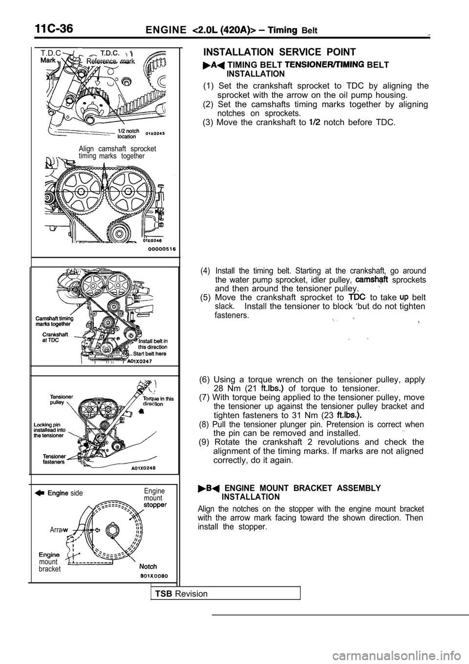
ENGINE Belt
Reference mark
T.D.C.
Align camshaft sprockettimingmarks together
side
Arra
mount
bracket Engine
mount
INSTALLATION SERVICE POINT
TIMING BELT BELT
INSTALLATION
(1) Set the crankshaft sprocket to TDC by aligning the
sprocket with the arrow on the oil pump housing.
(2) Set the camshafts timing marks together by alig ning
notches on sprockets.
(3) Move the crankshaft to notch before TDC.
(4) Install the timing belt. Starting at the crankshaft, go around
the water pump sprocket, idler pulley, sprockets
and then around the tensioner pulley.
(5) Move the crankshaft sprocket to to take belt
slack.Install the tensioner to block ‘but do not tighten
fasteners.
(6) Using a torque wrench on the tensioner pulley, apply
28 Nm (21
of torque to tensioner..
(7) With torque being applied to the tensioner pull ey, move
the tensioner up against the tensioner pulley brack et and
tighten fasteners to 31 Nm (23
(8) Pull the tensioner plunger pin. Pretension is correct when
the pin can be removed and installed.
(9) Rotate the crankshaft 2 revolutions and check t he
alignment of the timing marks. If marks are not ali gned
correctly, do it again.
ENGINE MOUNT BRACKET ASSEMBLY
INSTALLATION
Align the notches on the stopper with the engine mo unt bracket
with the arrow mark facing toward the shown direction. Then
install the stopper.
TSB Revision
Page 281 of 2103
ENGINE On-vehicle Service’
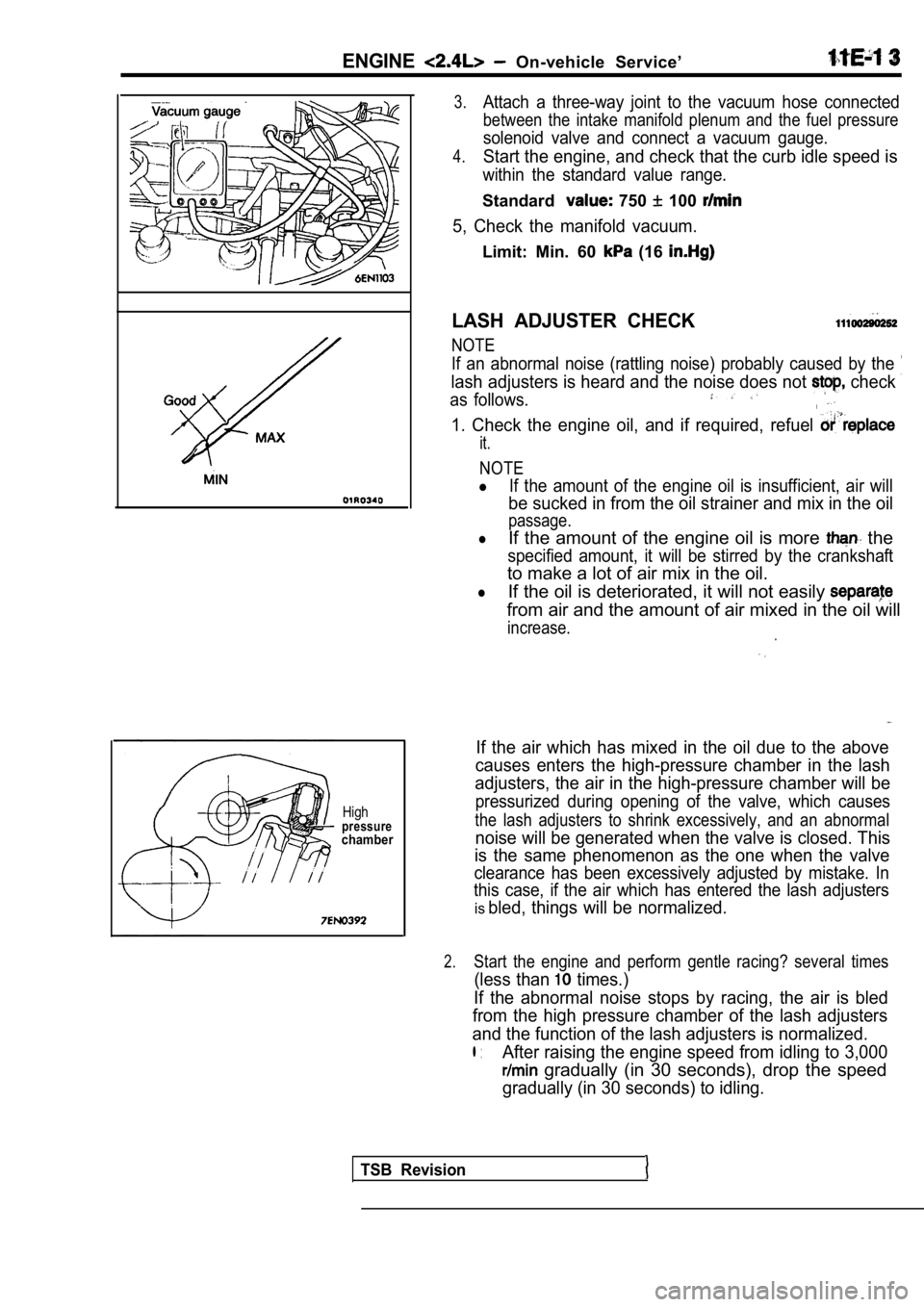
Highpressurechamber
3.Attach a three-way joint to the vacuum hose connected
between the intake manifold plenum and the fuel pressure
solenoid valve and connect a vacuum gauge.
4.Start the engine, and check that the curb idle speed is
within the standard value range.
Standard 750 100
5, Check the manifold vacuum.
Limit: Min. 60 (16
LASH ADJUSTER CHECK
NOTE
If an abnormal noise (rattling noise) probably caus ed by the
lash adjusters is heard and the noise does not check
as follows.
1. Check the engine oil, and if required, refuel
it.
NOTE
lIf the amount of the engine oil is insufficient, air will
be sucked in from the oil strainer and mix in the o il
passage.
lIf the amount of the engine oil is more the
specified amount, it will be stirred by the cranksh aft
to make a lot of air mix in the oil.
lIf the oil is deteriorated, it will not easily
from air and the amount of air mixed in the oil will
increase.
If the air which has mixed in the oil due to the ab ove
causes enters the high-pressure chamber in the lash
adjusters, the air in the high-pressure chamber wil l be
pressurized during opening of the valve, which caus es
the lash adjusters to shrink excessively, and an abnormal
noise will be generated when the valve is closed. This
is the same phenomenon as the one when the valve
clearance has been excessively adjusted by mistake. In
this case, if the air which has entered the lash ad justers
isbled, things will be normalized.
2.Start the engine and perform gentle racing? several times
(less than times.)
If the abnormal noise stops by racing, the air is b led
from the high pressure chamber of the lash adjuster s
and the function of the lash adjusters is normalize d.
l :After raising the engine speed from idling to 3,000
gradually (in 30 seconds), drop the speed
gradually (in 30 seconds) to idling.
TSB Revision
Page 376 of 2103
![MITSUBISHI SPYDER 1990 Service Repair Manual 12-4 L U B R I C A T I O N
EngineI
Turbo
4. Supply new engine oil through the oil filler.Engine oil total quantity:[including oil filter and oil cooler]
Engine (Non-turbo) arid MITSUBISHI SPYDER 1990 Service Repair Manual 12-4 L U B R I C A T I O N
EngineI
Turbo
4. Supply new engine oil through the oil filler.Engine oil total quantity:[including oil filter and oil cooler]
Engine (Non-turbo) arid](/manual-img/19/57345/w960_57345-375.png)
12-4 L U B R I C A T I O N
EngineI
Turbo
4. Supply new engine oil through the oil filler.Engine oil total quantity:[including oil filter and oil cooler]
Engine (Non-turbo) arid
4 . 3 (4 q t s . )
Engine (Turbo)>
4.4
(4.6 qts.)
5. Start and run the engine a
minutes.
6.Stop the engine and check the engine oil level is w ithin
the level range indicated on the oil dipstick.
.
NOTE
may be used for operation in very cold weather
areas where the lowest ambient temperature is below
OIL REPLACEMENT
1. Remove the engine oil filler cap.
2.Remove the engine oil drain plug, and drain out the engine
o i l .
3.Remove the engine oil filter by using the oil filter wrench.
4.Clean the oil filter mounting, surface of the oil f ilter bracket.
5. Coat engine oil to the O-ring of’new filter: .
6.Screw on the oil filter by hand until it touchesthe surface
of the flange and then tighten it with. the filter wrench:
etc.
Engine (Turbo) Engine>
lFor One full turn or 14 Nm
lFor or 17 Nm (12
E n g i n e ( N o n - t u r b o ) >
lFor 090: turn or 21 Nm (15
7. Add new engine oil through the oil filter.
8. Start and run engine and check for engine oil le aks.
9. After stopping engine, check oil level and reple nish as
necessary.
TSB Revision
Page 390 of 2103
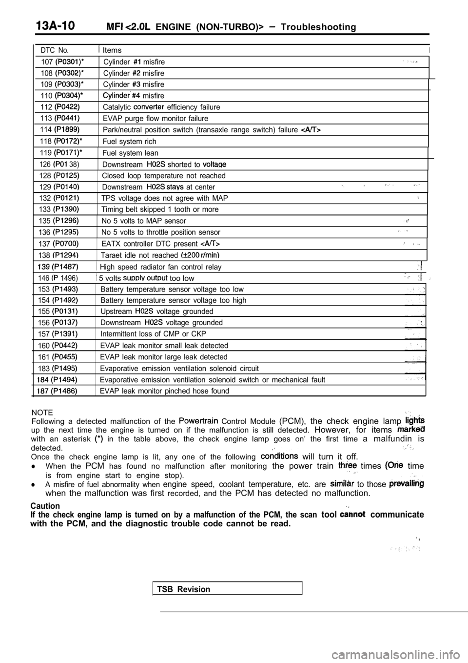
ENGINE (NON-TURBO)> Troubleshooting
DTC No. ItemsI
107
108
109
110
112
113
114
118
119
126 38)
Cylinder misfire
Cylinder
misfire
Cylinder
misfire
misfire
Catalytic
efficiency failure
EVAP purge flow monitor failure
Park/neutral position switch (transaxle range switc h) failure
Fuel system rich
Fuel system lean
Downstream
shorted to
128Closed loop temperature not reached
129
Downstream at center
132
133
TPS voltage does not agree with MAP
Timing belt skipped 1 tooth or more
135No 5 volts to MAP sensor
136No 5 volts to throttle position sensor
137EATX controller DTC present
138Taraet idle not reached
High speed radiator fan control relay
146 1496)
153
154
155
156
157
160
161
183
5 volts too low
Battery temperature sensor voltage too low
Battery temperature sensor voltage too high
Upstream
voltage grounded
Downstream
voltage grounded
Intermittent loss of CMP or CKP
EVAP leak monitor small leak detected
EVAP leak monitor large leak detected
Evaporative emission ventilation solenoid circuit
Evaporative emission ventilation solenoid switch or mechanical fault
EVAP leak monitor pinched hose found
NOTE
Following a detected malfunction of the Control Module (PCM), the check engine lamp
up the next time the engine is turned on if the mal function is still detected. However, for items
with an asterisk in the table above, the check engine lamp goes on’ the first time a malfundin is
detected.
Once the check engine lamp is lit, any one of the f ollowing
will turn it off.
lWhen the PCMhas found no malfunction after monitoring the power train times time
is from engine start to engine stop).
lA misfire of fuel abnormality when engine speed, coolant temperature, etc. are to those
when the malfunction was first recorded, and the PCM has detected no malfunction.
Caution
If the check engine lamp is turned on by a malfunct ion of the PCM, the scan tool communicate
with the PCM, and the diagnostic trouble code canno t be read.
,
TSB Revision