1990 MITSUBISHI SPYDER change time
[x] Cancel search: change timePage 192 of 2103
ENGINECamshaft and
554
.
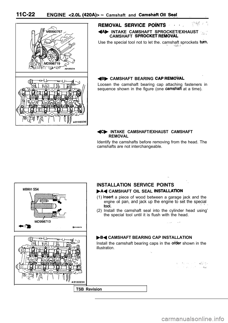
INTAKE CAMSHAFT SPROCKET/EXHAUST
CAMSHAFT
Use the special tool not to let the. camshaft sprockets
CAMSHAFT BEARING
Loosen the camshaft bearing cap attaching fasteners in
sequence shown in the figure (one
at a time).
INTAKE CAMSHAFT/EXHAUST CAMSHAFT REMOVAL
Identify the camshafts before removing from the hea d. The
camshafts are not interchangeable.
INSTALLATION SERVICE POINTS
CAMSHAFT OIL SEAL
(1) a piece of wood between a garage jack and the
engine oil pan, and jack up the engine to set the special .
(2) Install the camshaft seal into the cylinder hea d using’
the special tool until it is flush with the head.
CAMSHAFT BEARING CAP INSTALLATION
Install the camshaft bearing caps in the
shown in the
illustration.
TSB Revision
Page 234 of 2103
OVERHAUL Camshaft and Cam
askets
CAMSHAFT AND CAM FOLLOWER
11301990010
REMOVAL
(1) Remove the cylinder head cover fasteners.
(2) Remove cylinder head cover from cylinder head.
, ,
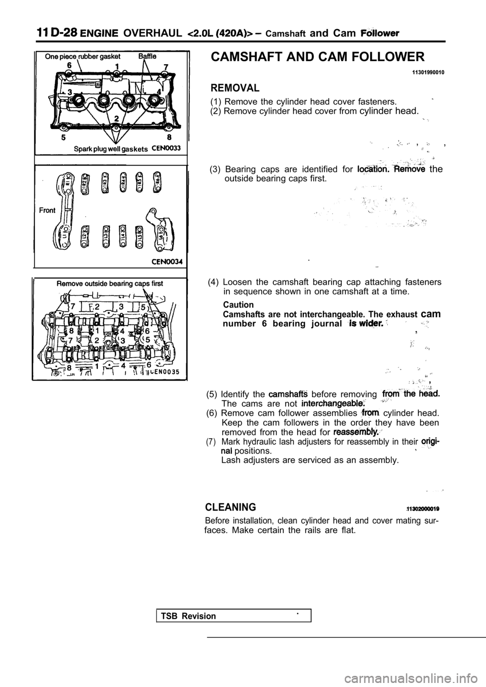
(3) Bearing caps are identified for the
outside bearing caps first.
.
(4) Loosen the camshaft bearing cap attaching faste ners
in sequence shown in one camshaft at a time.
Caution
Camshafts are not interchangeable. The exhaust
cam
number 6 bearing journal ,
,
(5) Identify the
before removing
The cams are not
(6) Remove cam follower assemblies cylinder head.
Keep the cam followers in the order they have been
removed from the head for
(7)Mark hydraulic lash adjusters for reassembly in the ir
positions.
Lash adjusters are serviced as an assembly.
CLEANING
Before installation, clean cylinder head and cover mating sur-
faces. Make certain the rails are flat.
TSB Revision.
Page 383 of 2103
ENGINE (NON-TURBO)> General
FUEL INJECTION
ENGINE (NON-TURBO)>
GENERAL INFORMATION
The Fuel Injection System consists
of sensors which detect the engine conditions,
the POWERTRAIN CONTROL MODULE(PCM) which controls the system based on
signals from these sensors, and actuators
which operate under the control of the PCM.
FUEL INJECTION CONTROL
The injector drive times and injector timing are
controlled so that the optimum air/fuel mixture
is supplied to the engine to correspond to the
continually-changing engine operation condi-
tions.
A single injector is mounted at the intake port
of each cylinder. Fuel is sent under pressure
from the fuel tank by the fuel pump, with the
pressure regulated by the fuel pressureregulator. The regulated fuel is distributed
to each of the injectors. Fuel injection is normally carried out once for
each cylinder for every two rotations of the
crankshaft. The firing order is
This
IDLE AIR CONTROL The idle speed’ is kept at the optimum speed
by controlling the amount of air that bypasses
the throttle valve in accordance with changes in idling conditions and engine load during
idling.
The PCM drives the idle air control (IAC) motor
to keep the engine running at the idle
target speed in accordance with the engine
IGNITION TIMING CONTROL
The ignition power transistor is built into the
PCM. It turns the ignition primary circuit on
and off to respectively supply and cut off primary
current flow to the ignition coil. The PCM carries
activities such fuel
injection control, idle air control and ignition
timing control.
In addition, the
diagnostict e s twhich simplify
troubleshooting when a problem develops.
is called The PCM
air/fuel mixture by carrying out “open-loop”
control when the engine is cold or operating
under high load conditions in to maintain
engine performance.
In addition, when the engine warm or
operating under normal
the PCM
controls the air/fuel mixture by using the heated
oxygen sensor signal to carry out “closed-loop”
control in order to obtain the theoretical air/fuel
mixture ratio that provides the maximum
cleaning
from the three way
catalyst.
coolant temperature and air conditioning load.
In addition, when the air conditioning switch
is turned off and on while the engine is idling,
the
motor operates to adjust the throttle
valve bypass air amount in accordance with
the engine load conditions in order to avoid
fluctuations in the engine speed.
This controls the ignition timing in order to
provide the optimum ignition timing with respect
to the engine operating conditions. The ignition
timing is determined by the PCM from the
engine speed, intake air volume, engine coolant
temperature and atmospheric pressure.
TSB Revision
Page 451 of 2103
![MITSUBISHI SPYDER 1990 Service Repair Manual ( N O N - T U R B O ) >
Scan tool 133
Code General scan tool Timing Belt Skipped 1 Tooth or
No.More
11 ,,
[Comment]l Timing belt improperly BackgroundlThe PCM uses voltage signal MITSUBISHI SPYDER 1990 Service Repair Manual ( N O N - T U R B O ) >
Scan tool 133
Code General scan tool Timing Belt Skipped 1 Tooth or
No.More
11 ,,
[Comment]l Timing belt improperly BackgroundlThe PCM uses voltage signal](/manual-img/19/57345/w960_57345-450.png)
( N O N - T U R B O ) >
Scan tool 133
Code General scan tool Timing Belt Skipped 1 Tooth or
No.More
11 ,,
[Comment]l Timing belt improperly BackgroundlThe PCM uses voltage signals generated by the camsh aft position sensor and l C r a n k s h a f t s e n s o r
position sensors to determine engine synchronizatio n.
l lif these signals become out of sync, this DTC is pr oduced.
l Range of Check connected l With the engine running, every 44 ms an inhibit con dition is looked for as follows:lwide-open throttle, large change in MAP, cold engine, insufficient start to run time, Crankshaft position sensor eriy connected outside given windowslCamshaft’s relative position not lif an inhibit condition does not exist, the misalignment between the camshaft and crankshaftone of the following have been serviced:
is monitored.
Set Condition camshaft, timing. ten-
When the camshaft position sensor is offset from th e crankshaft position sensor one tooth
sprocket,or more.PCM the
NGCheck the following Repair
,Check the camshaft position sensor.
(Refer to GROUP 16 Ignition System.)
OK
Check the crankshaft position se
(Refer to GROUP 16 IgnitionSystem.)
OK
I
NG Repair
,
Check the timing belt. (Refer to GROUP 11
Timing Belt.)
Caution
When the following parts arereplaced with new ones, be sure to use the scan to
the camshaft position sensor with the crankshaft po sition sensor again or disconnect the negative
battery cable for 10 seconds or more:
camshaft, camshaft sprocket, timing belt, tensioner, cylinder head, head gasket, crankshaft sprocket,
crankshaft, cylinder block, etc.
TSB Revision
Page 459 of 2103
![MITSUBISHI SPYDER 1990 Service Repair Manual ,
-- Scan tool 156,I
C o d e G e n e r a l s c a n t o o l D o w n s t r e a m to
No. G r o u n d
21
[Comment]l Downstream heated oxygen Backgroundl harness and connectors lWhen MITSUBISHI SPYDER 1990 Service Repair Manual ,
-- Scan tool 156,I
C o d e G e n e r a l s c a n t o o l D o w n s t r e a m to
No. G r o u n d
21
[Comment]l Downstream heated oxygen Backgroundl harness and connectors lWhen](/manual-img/19/57345/w960_57345-458.png)
,
-- Scan tool 156,I
C o d e G e n e r a l s c a n t o o l D o w n s t r e a m to
No. G r o u n d
21
[Comment]l Downstream heated oxygen Backgroundl harness and connectors lWhen the heated oxygen sensor temperature is low, t he sensor has the same electrical
l PCM failed characteristics as an insulator.lThe heated oxygen sensor output signal line is That is is approx. when the heated oxygen sensor temperature is low.If the heated oxygen sensor output signal line is g rounded, will become lRange of checkl Engine coolant temperature when the engine starts: or lessl Within three seconds after the engine starts
Set Conditions
The heated oxygen sensor output signal line is
or less.
NGCheck the harness I .oxygen sensor connector.. , ,
OK
Replace the PCM.
11
[Comment]Background , connectedlAfter the engine has been started, the PCM maintain s an expected camshaft port l position
Scan tool 157,General scan toolIntermittent Loss of CMP CKP Probable cause
value. connectedlAt every crankshaft leading edge, this value is updated to reflect the expected
.Camshaft position sensor change in the cam level.
l lAt every crankshaft trailing edge, this value is compared to the true port level. sensor improperly lIf there is a disagreement between two values, then the diagnostic code isset.l sensor
Range of Check
l Engine: running
Set Condition
l Cam and crank signals have been out of sync, than times.
N GCheck the following connectors:. A-l 06
OK
__Check no cam sync. signal at PCM. (Refer to INSPECTION PROCEDURE FOR DIAGNOSTIC TROUBLE
CODE.
Check no crank reference signal at PCM. (Refer to INSPECTION PROCEDURE FOR DIAGNOSTIC TROUBLE
TSB Revision
Page 518 of 2103
ENGINE
AND ENGINE> G e n e r a l
ENGINE (TURBO) AND ENGINE>13199910319
GENERAL INFORMATIONThe
Fuel Injection System consists
of sensors which detect the engine conditions,
the ENGINE CONTROL MODULE (ECM) which
controls the system based on signals from these
sensors, and actuators which operate under
the control of the ECM.
FUEL INJECTION CONTROL
The injector drive times and injector timing are
controlled so that the optimum air/fuel mixture
is supplied to the engine to correspond to the
continually-changing engine operation condi-
tions.
A single injector is mounted at the intake port
of each cylinder. Fuel is sent under pressure
from the fuel tank by the fuel pump, with the
pressure regulated by the fuel pressure regula-
tor. The regulated fuel is distributed to each
of the injectors.
Fuel injection is normally carried out once for
each cylinder for every two rotations of the
IDLE AIR CONTROL The idle speed is kept at the optimum speed
by controlling the amount of air that bypasses
the throttle valve in accordance with changes
in idling conditions and engine load during id-
ling.
The ECM drives the idle air control (IAC) motor
to keep the engine running at the pre-set idle
target speed in accordance with the engine
IGNITION TIMING CONTROL
The ignition power transistor located in the igni-
tion primary circuit turns ON and OFF to control
the primary current flow to the ignition coil.
This controls the ignition timing in order to pro-
vide the optimum ignition timing with respect The ECM carries out activities such as fuel
injection control, idle air control and ignition
timing control.
In addition, the ECM is equipped with several
diagnostic test modes which simplify trouble-
shooting when a problem develops.
. .
crankshaft. The firing is This
is called
The provides a richer
air/fuel mixture by carrying out “open-loop” con-
trol when the engine is cold or operating under high load
in order to maintain engine
performance. In addition, when the engine is warm or operat-
ing under normal conditions, the ECM controls
the air/fuel mixture by using the heated oxygen
sensor signal to carry out “closed-loop” control
in order to obtain the theoretical air/fuel mixture
ratio that provides the maximum cleaning per-
formance from the three way catalyst.
coolant temperature and air conditioning load.
In addition, when the air’ conditioning switch
is turned off and on while the
is
the motor operates to adjust the throttle
valve bypass air amount in accordance with
the engine load conditions in order to avoid
fluctuations in the engine speed.
to the engine operating conditions. The ignition
timing is determined by the ECM from the en-
gine speed, intake air volume, engine coolant
temperature and atmospheric pressure.
TSB Revision
Page 530 of 2103
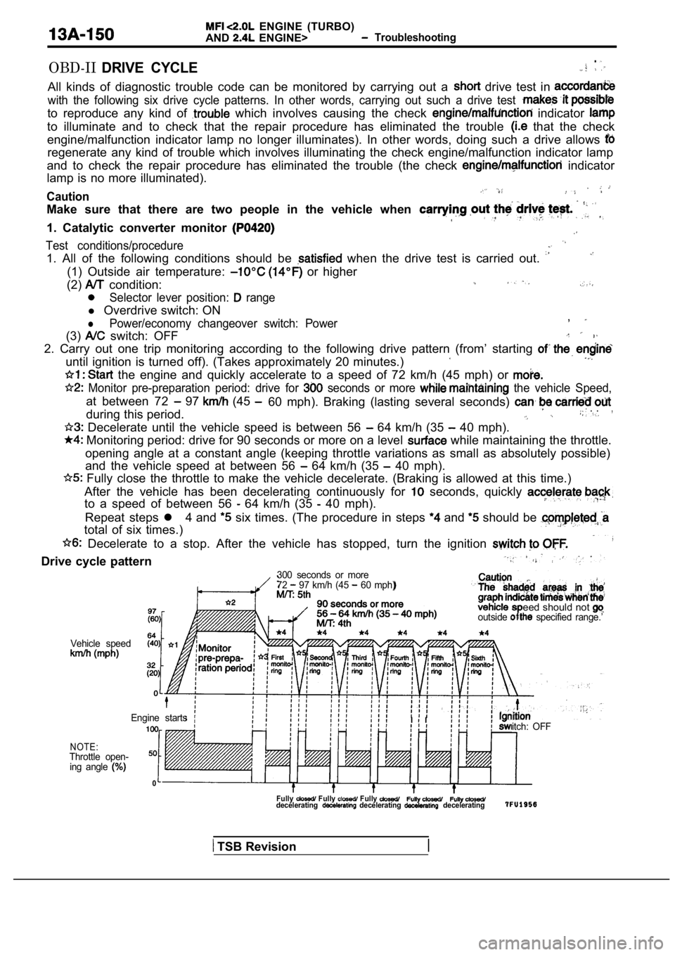
ENGINE (TURBO)
AND
ENGINE> Troubleshooting
OBD-IIDRIVE CYCLE.
All kinds of diagnostic trouble code can be monitor ed by carrying out a drive test in
with the following six drive cycle patterns. In other words, carrying out such a drive test
to reproduce any kind of which involves causing the check indicator
to illuminate and to check that the repair procedur e has eliminated the trouble that the check
engine/malfunction indicator lamp no longer illumin ates). In other words, doing such a drive allows
regenerate any kind of trouble which involves illuminating the check engine/malfunction indicator lamp
and to check the repair procedure has eliminated th e trouble (the check
indicator
lamp is no more illuminated).
Caution
Make sure that there are two people in the vehicle when
1. Catalytic converter monitor
Test conditions/procedure
1. All of the following conditions should be when the drive test is carried out.
(1) Outside air temperature: or higher
(2)
condition:
Selector lever position: range
l Overdrive switch: ON
lPower/economy changeover switch: Power,
(3) switch: OFF
2. Carry out one trip monitoring according to the f ollowing drive pattern (from’ starting
until ignition is turned off). (Takes approximately 20 minutes.)
the engine and quickly accelerate to a speed of 72 km/h (45 mph) or
Monitor pre-preparation period: drive for seconds or more the vehicle Speed,
at between 72 97 (45
during this period.60 mph). Braking (lasting several seconds) . .,
Decelerate until the vehicle speed is between 56 64 km/h (35 40 mph).
Monitoring period: drive for 90 seconds or more on
a level while maintaining the throttle.
opening angle at a constant angle (keeping throttle variations as small as absolutely possible)
and the vehicle speed at between 56
64 km/h (35 40 mph).
Fully close the throttle to make the vehicle decel erate. (Braking is allowed at this time.)
After the vehicle has been decelerating continuousl y for
seconds, quickly
to a speed of between 56 64 km/h (35 40 mph).
Repeat steps l 4 and
six times. (The procedure in steps and should be
total of six times.)
Decelerate to a stop. After the vehicle has stoppe d, turn the ignition
Drive cycle pattern
300 seconds or more
72 97 km/h (45 60 mph)
eed should not outside specified range.’
Vehicle speed
NOTE:Throttle open-ing angle
0
itch: OFF
Engine startsI I
Fully Fully Fully decelerating decelerating decelerating
TSB Revision
Page 531 of 2103
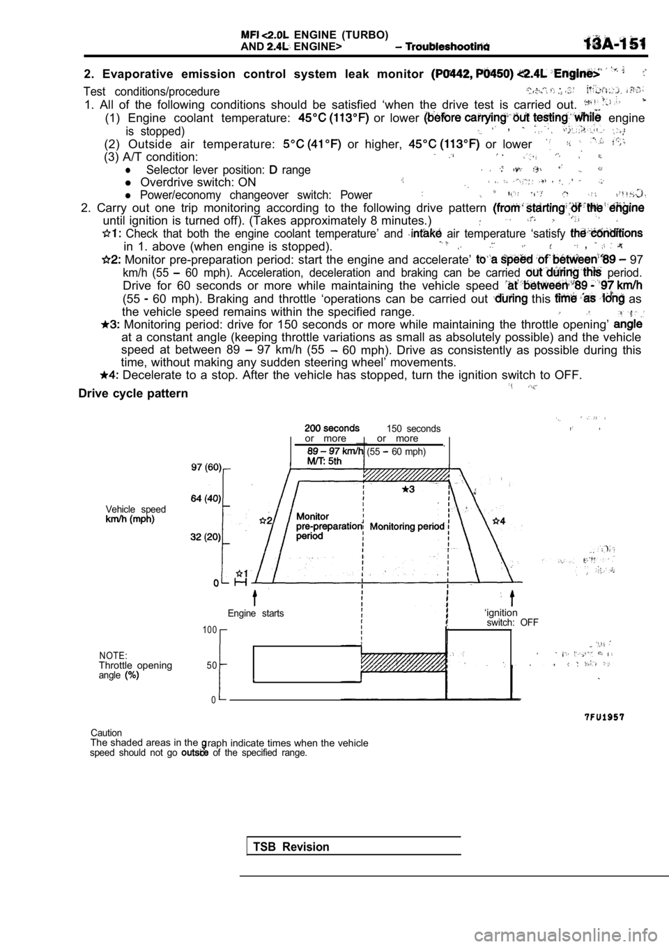
ENGINE (TURBO)
AND
ENGINE>
2. Evaporative emission control system leak monitor
Test conditions/procedure , . .
1. All of the following conditions should be satisfied ‘when the drive test is carried out.
(1) Engine coolant temperature: or lower engine
is stopped) ,
(2) Outside air temperature: or higher, or lower
(3) A/T condition: .
lSelector lever position: range .
l Overdrive switch: ON
l Power/economy changeover switch: Power
2. Carry out one trip monitoring according to the f ollowing drive pattern
until ignition is turned off). (Takes approximately 8 minutes.)
Check that both the engine coolant temperature’ an d air temperature ‘satisfy
in 1. above (when engine is stopped). ,
Monitor pre-preparation period: start the engine and accelerate’ 97
km/h (55 60 mph). Acceleration, deceleration and braking ca n be carried period.
Drive for 60 seconds or more while maintaining the vehicle speed
(55 60 mph). Braking and throttle ‘operations can be carried out this as
the vehicle speed remains within the specified rang e.
Monitoring period: drive for 150 seconds or more w hile maintaining the throttle opening’
at a constant angle (keeping throttle variations as small as absolutely possible) and the vehicle
speed at between 89
97 km/h (55 60 mph). Drive as consistently as possible during this
time, without making any sudden steering wheel’ mov ements.
Decelerate to a stop. After the vehicle has stopped, turn the ignition switch to OFF.
Drive cycle pattern
150 seconds
Vehicle speed
NOTE:Throttle openingangle
or more __ or more
.
(55 60 mph)
Engine starts
1 0 0
50
0
I
‘ignitionswitch: OFF
,
CautionThe shaded areas in theraph indicate times when the vehiclespeed should not go of the specified range.
TSB Revision