1990 MITSUBISHI SPYDER steering wheel
[x] Cancel search: steering wheelPage 3 of 2103
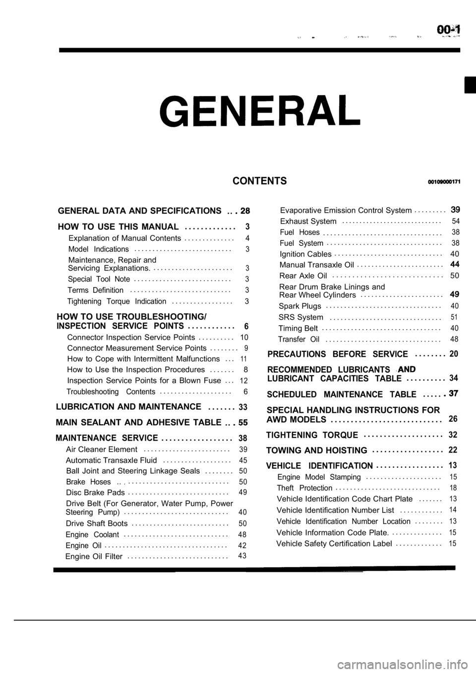
CONTENTS
GENERAL DATA AND SPECIFICATIONS. .
HOW TO USE THIS MANUAL. . . . . . . . . . . . .3
Explanation of Manual Contents. . . . . . . . . . . . . .4
Model Indications
. . . . . . . . . . . . . . . . . . . . . . . . . . .3
Maintenance, Repair and
Servicing Explanations. . . . . . . . . . . . . . . . . . . . . . .
3
Special Tool Note. . . . . . . . . . . . . . . . . . . . . . . . . . .3
Terms Definition. . . . . . . . . . . . . . . . . . . . . . . . . . . .3
Tightening Torque Indication. . . . . . . . . . . . . . . . .3
HOW TO USE TROUBLESHOOTING/
INSPECTION SERVICE POINTS. . . . . . . . . . . .6
Connector Inspection Service Points
. . . . . . . . . .10
Connector Measurement Service Points . . . . . . . .9
How to Cope with Intermittent Malfunctions . . .11
How to Use the Inspection Procedures
. . . . . . .
8
Inspection Service Points for a Blown Fuse . . .
12
Troubleshooting Contents. . . . . . . . . . . . . . . . . . . .6
LUBRICATION AND MAINTENANCE . . . . . . .33
MAIN SEALANT AND ADHESIVE TABLE
. .
MAINTENANCE SERVICE. . . . . . . . . . . . . . . . . .38
Air Cleaner Element. . . . . . . . . . . . . . . . . . . . . . . .39
Automatic Transaxle Fluid
. . . . . . . . . . . . . . . . . . .45
Ball Joint and Steering Linkage Seals
. . . . . . . .50
Brake Hoses.... . . . . . . . . . . . . . . . . . . . . . . . . . . .50
Disc Brake Pads. . . . . . . . . . . . . . . . . . . . . . . . . . . .49
Drive Belt (For Generator, Water Pump, Power
Steering Pump). . . . . . . . . . . . . . . . . . . . . . . . . . . . .40
Drive Shaft Boots
. . . . . . . . . . . . . . . . . . . . . . . . . . .50
Engine Coolant. . . . . . . . . . . . . . . . . . . . . . . . . . . . .48
Engine Oil. . . . . . . . . . . . . . . . . . . . . . . . . . . . . . . . . .42
Engine Oil Filter. . . . . . . . . . . . . . . . . . . . . . . . . . . .43
Evaporative Emission Control System . . . . . . . . .
Exhaust System. . . . . . . . . . . . . . . . . . . . . . . . . . . . .54
Fuel Hoses. . . . . . . . . . . . . . . . . . . . . . . . . . . . . . . . .38
Fuel System. . . . . . . . . . . . . . . . . . . . . . . . . . . . . . . .38
Ignition Cables. . . . . . . . . . . . . . . . . . . . . . . . . . . . . .
40
Manual Transaxle Oil . . . . . . . . . . . . . . . . . . . . . . . .
Rear Axle Oil. . . . . . . . . . . . . . . . . . . . . . . . . . . .
50
Rear Drum Brake Linings and
Rear Wheel Cylinders . . . . . . . . . . . . . . . . . . . . . . .
Spark Plugs. . . . . . . . . . . . . . . . . . . . . . . . . . . . . . . .40
SRS System . . . . . . . . . . . . . . . . . . . . . . . . . . . . . . .51
Timing Belt. . . . . . . . . . . . . . . . . . . . . . . . . . . . . . . . .40
Transfer Oil. . . . . . . . . . . . . . . . . . . . . . . . . . . . . . . .48
PRECAUTIONS BEFORE SERVICE. . . . . . . .20
RECOMMENDED LUBRICANTS
LUBRICANT CAPACITIES TABLE. . . . . . . . . .34
SCHEDULED MAINTENANCE TABLE. . . . .
SPECIAL HANDLING INSTRUCTIONS FOR
AWD MODELS . . . . . . . . . . . . . . . . . . . . . . . . . . . .
26
TIGHTENING TORQUE. . . . . . . . . . . . . . . . . . . .32
TOWING AND HOISTING . . . . . . . . . . . . . . . . . .22
VEHICLE IDENTIFICATION. . . . . . . . . . . . . . . . .13
Engine Model Stamping. . . . . . . . . . . . . . . . . . . . .15
Theft Protection. . . . . . . . . . . . . . . . . . . . . . . . . . . . .18
Vehicle Identification Code Chart Plate
. . . . . . .13
Vehicle Identification Number List. . . . . . . . . . . .14
Vehicle Identification Number Location. . . . . . . .13
Vehicle Information Code Plate.. . . . . . . . . . . . . .15
Vehicle Safety Certification Label
. . . . . . . . . . . . .15
Page 22 of 2103
GENERAL before Service
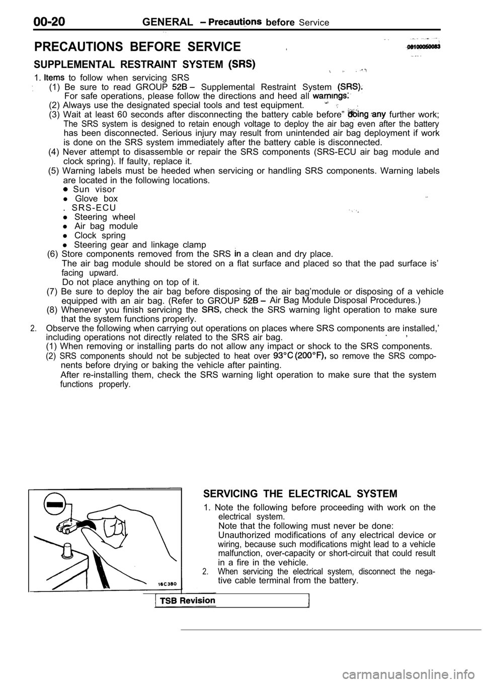
PRECAUTIONS BEFORE SERVICE.
SUPPLEMENTAL RESTRAINT SYSTEM
1. to follow when servicing SRS
(1) Be sure to read GROUP Supplemental Restraint System
For safe operations, please follow the directions a nd heed all
(2) Always use the designated special tools and tes t equipment.
(3) Wait at least 60 seconds after disconnecting the battery cable before” further work;
The SRS system is designed to retain enough voltage to deploy the air bag even after the battery
has been disconnected. Serious injury may result from unintended air bag deployment if work
is done on the SRS system immediately after the bat tery cable is disconnected.
(4) Never attempt to disassemble or repair the SRS components (SRS-ECU air bag module and
clock spring). If faulty, replace it.
(5) Warning labels must be heeded when servicing or handling SRS components. Warning labels
are located in the following locations.
Sun visor
l Glove box
. S R S - E C U
l Steering wheel
l Air bag module
l Clock spring
l Steering gear and linkage clamp
(6) Store components removed from the SRS
a clean and dry place.
The air bag module should be stored on a flat surfa ce and placed so that the pad surface is’
facing upward.
Do not place anything on top of it.
(7) Be sure to deploy the air bag before disposing of the air bag’module or disposing of a vehicle
equipped with an air bag. (Refer to GROUP
Air Bag Module Disposal Procedures.)
(8) Whenever you finish servicing the
check the SRS warning light operation to make sure
that the system functions properly.
2.Observe the following when carrying out operations on places where SRS components are installed,’
.,
including operations not directly related to the SR S air bag.
(1) When removing or installing parts do not allow any impact or shock to the SRS components.
(2) SRS components should not be subjected to heat over so remove the SRS compo-
nents before drying or baking the vehicle after painting.
After re-installing them, check the SRS warning lig ht operation to make sure that the system
functions properly.
SERVICING THE ELECTRICAL SYSTEM
1. Note the following before proceeding with work o n the
electrical system.
Note that the following must never be done:
Unauthorized modifications of any electrical device or
wiring, because such modifications might lead to a vehicle
malfunction, over-capacity or short-circuit that co uld result
in a fire in the vehicle.
2.When servicing the electrical system, disconnect th e nega-
tive cable terminal from the battery.
Page 24 of 2103
GENERAL Towing and Hoisting
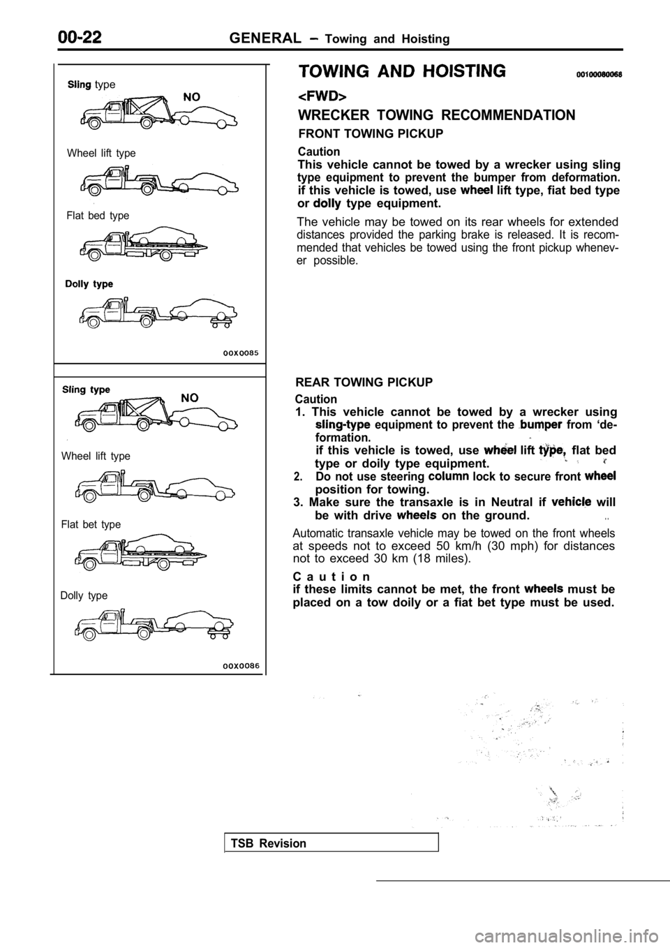
type
Wheel lift type
Flat bed type
Wheel lift type
Flat bet type
Dolly type
WRECKER TOWING RECOMMENDATION
FRONT TOWING PICKUP
Caution
This vehicle cannot be towed by a wrecker using sli ng
type equipment to prevent the bumper from deformati on.
if this vehicle is towed, use lift type, fiat bed type
or
type equipment.
The vehicle may be towed on its rear wheels for ext ended
distances provided the parking brake is released. It is recom-
mended that vehicles be towed using the front picku p whenev-
er possible.
REAR TOWING PICKUP
Caution
1. This vehicle cannot be towed by a wrecker using
equipment to prevent the from ‘de-
formation.
if this vehicle is towed, use lift flat bed
type or doily type equipment.
2.Do not use steering lock to secure front
position for towing.
3. Make sure the transaxle is in Neutral if
will
be with drive
on the ground.. .
Automatic transaxle vehicle may be towed on the fro nt wheels
at speeds not to exceed 50 km/h (30 mph) for distan ces
not to exceed 30 km (18 miles).
C a u t i o n
if these limits cannot be met, the front
must be
placed on a tow doily or a fiat bet type must be us ed.
TSB Revision
Page 52 of 2103

GENERAL Maintenance Service
2.Check the wheel cylinder boots for evidence, a’ brake
fluid leak. Visually check the
boots for tears or
cracks. (A slight amount of fluid on the boot may not
be a leak, but may be preservative assembly.)
Caution
The shoes for the right and left be,
replaced at the same time.
Never split or intermix brake
sets.
All four shoes must be replaced as a set.
Thickness of lining
Limit: 1.0 mm in.)
17. BRAKE HOSES (Check for
leaks)
Check of brake hoses and tubing should be
brake service operations.
The hoses should be checked for:
1.Correct length, severe surface cracking, pulling, scuffing
or worn spots. (If the fabric casing of the hoses i s exposed
by cracks of abrasion in the rubber hose cover, the hoses
should be replaced. Eventual deterioration of may
occur with possible bursting failure.)
2. Faulty installation, casing twisting or interfer ence
wheel,’ tire or chassis.
18. BALL JOINT AND STEERING SEALS
(Check for grease leaks damage)
1. These components, which are permanently lubricat ed
at the factory, do not require periodic lubrication. Damaged
seals and boots should be replaced to prevent leakage
or contamination of the grease.
2.Check the dust cover and boots for proper sealing, leakage
and damage. Replace them if defective.
19. DRIVE SHAFT BOOTS (Check for leaks
and damage)
1. These components, which are permanently lubricat ed
at the factory, do not require periodic Damaged
boots should be replaced to prevent leakage or contamina-
tion of the grease.
2.Check the boots for proper sealing, leakage and damage.
Replace it if defective.
AXLE OIL (Check oil level)-AWD
Remove the filler plug and check the oil level at bottom of
filler hole. If the oil level is slightly below the filler hole, it
is in satisfactory condition.
Page 54 of 2103
GENERAL Maintenance Service
0 0 0 0 0 1 6 7
Inflator case
CHECK
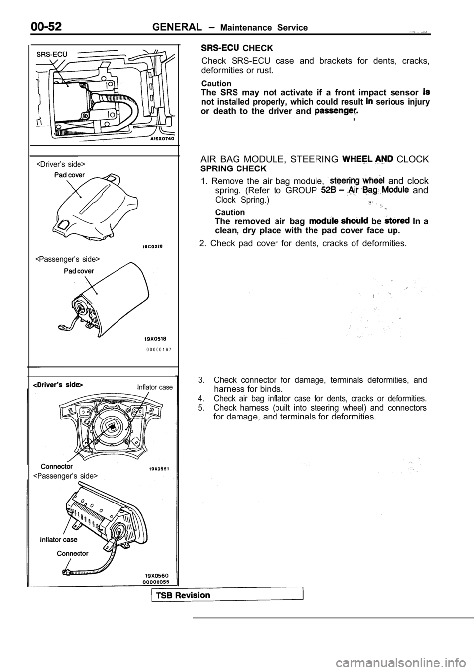
Check SRS-ECU case and brackets for dents, cracks,
deformities or rust.
Caution
The SRS may not activate if a front impact sensor
not installed properly, which could result serious injury
or death to the driver and ,
AIR BAG MODULE, STEERING
CLOCK
SPRING CHECK
1. Remove the air bag module,
and clock
spring. (Refer to GROUP
and
Clock Spring.)
Caution
The removed air bag be In a
clean, dry place with the pad cover face up.
2. Check pad cover for dents, cracks of deformities .
3.Check connector for damage, terminals deformities, and
harness for binds.
4.Check air bag inflator case for dents, cracks or deformities.
5.Check harness (built into steering wheel) and conne ctors
for damage, and terminals for deformities.
Page 55 of 2103
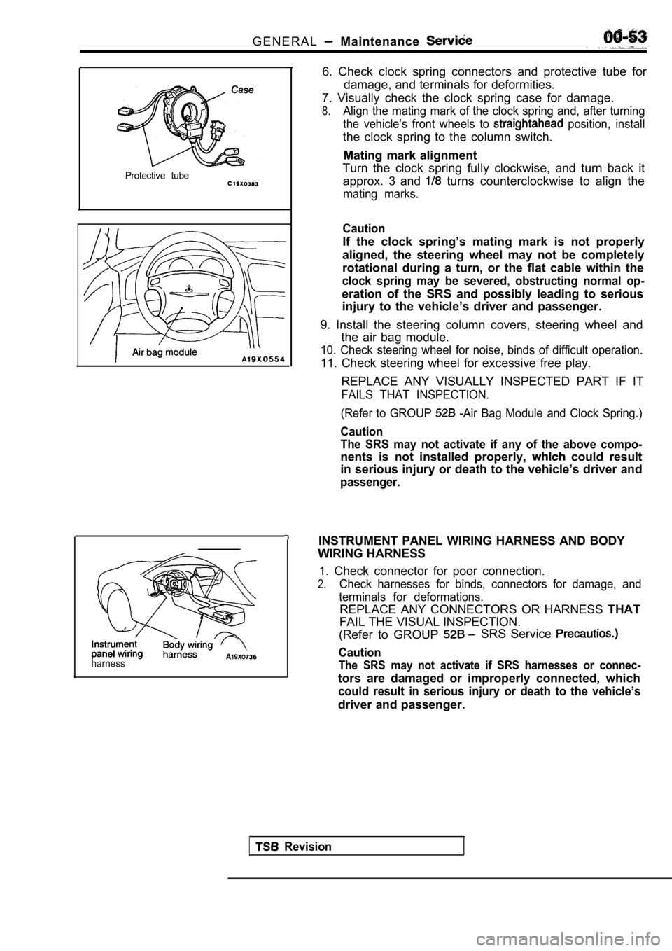
G E N E R A L Maintenance
Protective tube
harness
6. Check clock spring connectors and protective tube for
damage, and terminals for deformities.
7. Visually check the clock spring case for damage.
8.Align the mating mark of the clock spring and, afte r turning
the vehicle’s front wheels to
position, install
the clock spring to the column switch.
Mating mark alignment
Turn the clock spring fully clockwise, and turn bac k it
approx. 3 and
turns counterclockwise to align the
mating marks.
Caution
If the clock spring’s mating mark is not properly
aligned, the steering wheel may not be completely
rotational during a turn, or the flat cable within the
clock spring may be severed, obstructing normal op-
eration of the SRS and possibly leading to serious
injury to the vehicle’s driver and passenger.
9. Install the steering column covers, steering whe el and
the air bag module.
10. Check steering wheel for noise, binds of diffic ult operation.
11. Check steering wheel for excessive free play.
REPLACE ANY VISUALLY INSPECTED PART IF IT
FAILS THAT INSPECTION.
(Refer to GROUP
-Air Bag Module and Clock Spring.)
Caution
The SRS may not activate if any of the above compo-
nents is not installed properly, could result
in serious injury or death to the vehicle’s driver and
passenger.
INSTRUMENT PANEL WIRING HARNESS AND BODY
WIRING HARNESS
1. Check connector for poor connection.
2.Check harnesses for binds, connectors for damage, a nd
terminals for deformations.
REPLACE ANY CONNECTORS OR HARNESS THAT
FAIL THE VISUAL INSPECTION.
(Refer to GROUP
SRS Service
Caution
The SRS may not activate if SRS harnesses or connec -
tors are damaged or improperly connected, which
could result in serious injury or death to the vehicle’s
driver and passenger.
Revision
Page 58 of 2103
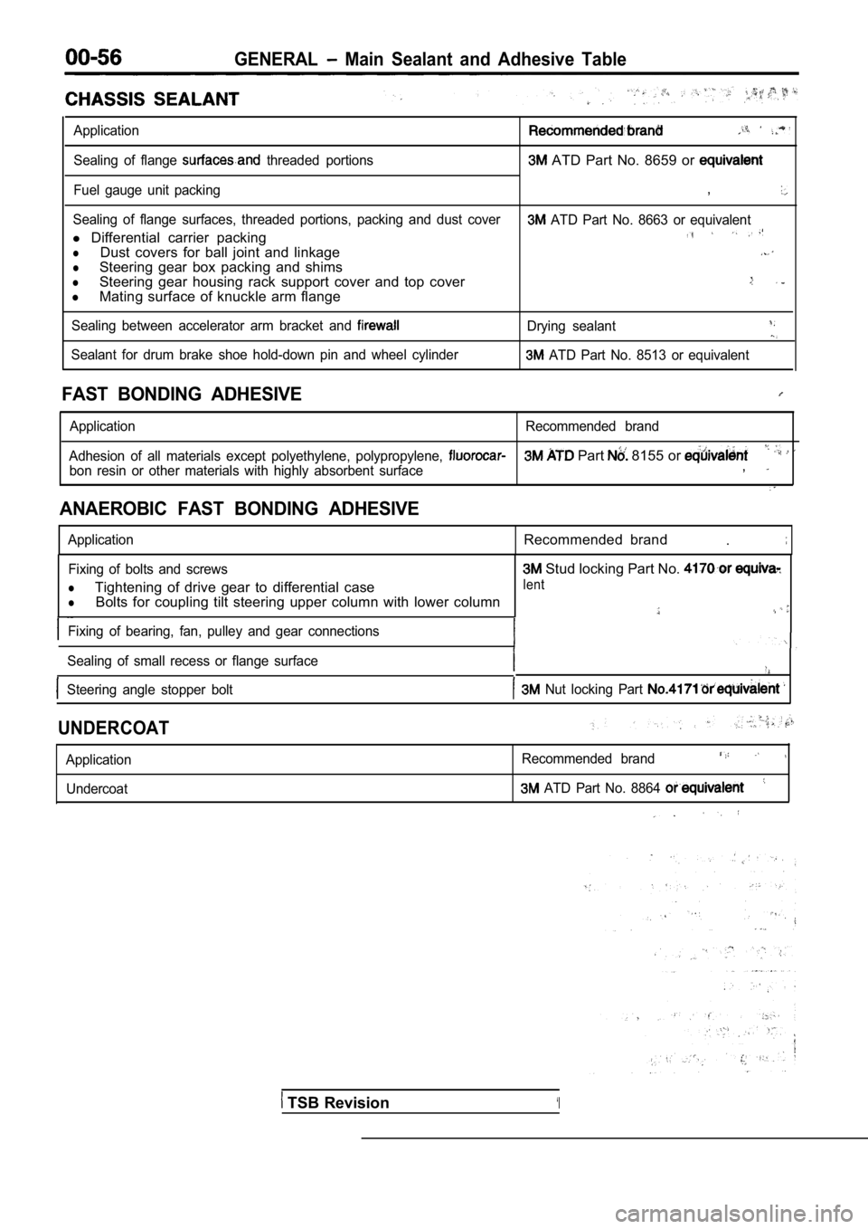
GENERAL Main Sealant and Adhesive Table
Application
Sealing of flange threaded portions ATD Part No. 8659 or
Fuel gauge unit packing,
Sealing of flange surfaces, threaded portions, packing and dust cover ATD Part No. 8663 or equivalent
l Differential carrier packing
lDust covers for ball joint and linkage
lSteering gear box packing and shims
lSteering gear housing rack support cover and top co ver
lMating surface of knuckle arm flange
Sealing between accelerator arm bracket and Drying sealant
Sealant for drum brake shoe hold-down pin and wheel cylinder ATD Part No. 8513 or equivalent
FAST BONDING ADHESIVE
Application Recommended brand
Adhesion of all materials except polyethylene, poly propylene,
Part 8155 or
bon resin or other materials with highly absorbent surface,
ANAEROBIC FAST BONDING ADHESIVE
ApplicationRecommended brand.
Fixing of bolts and screws
lTightening of drive gear to differential case
lBolts for coupling tilt steering upper column with lower column
Fixing of bearing, fan, pulley and gear connections
Sealing of small recess or flange surface
Steering angle stopper bolt Nut locking Part
Stud locking Part No.
lent
UNDERCOAT
Application Undercoat Recommended brand
ATD Part No. 8864
TSB Revision‘I
Page 271 of 2103
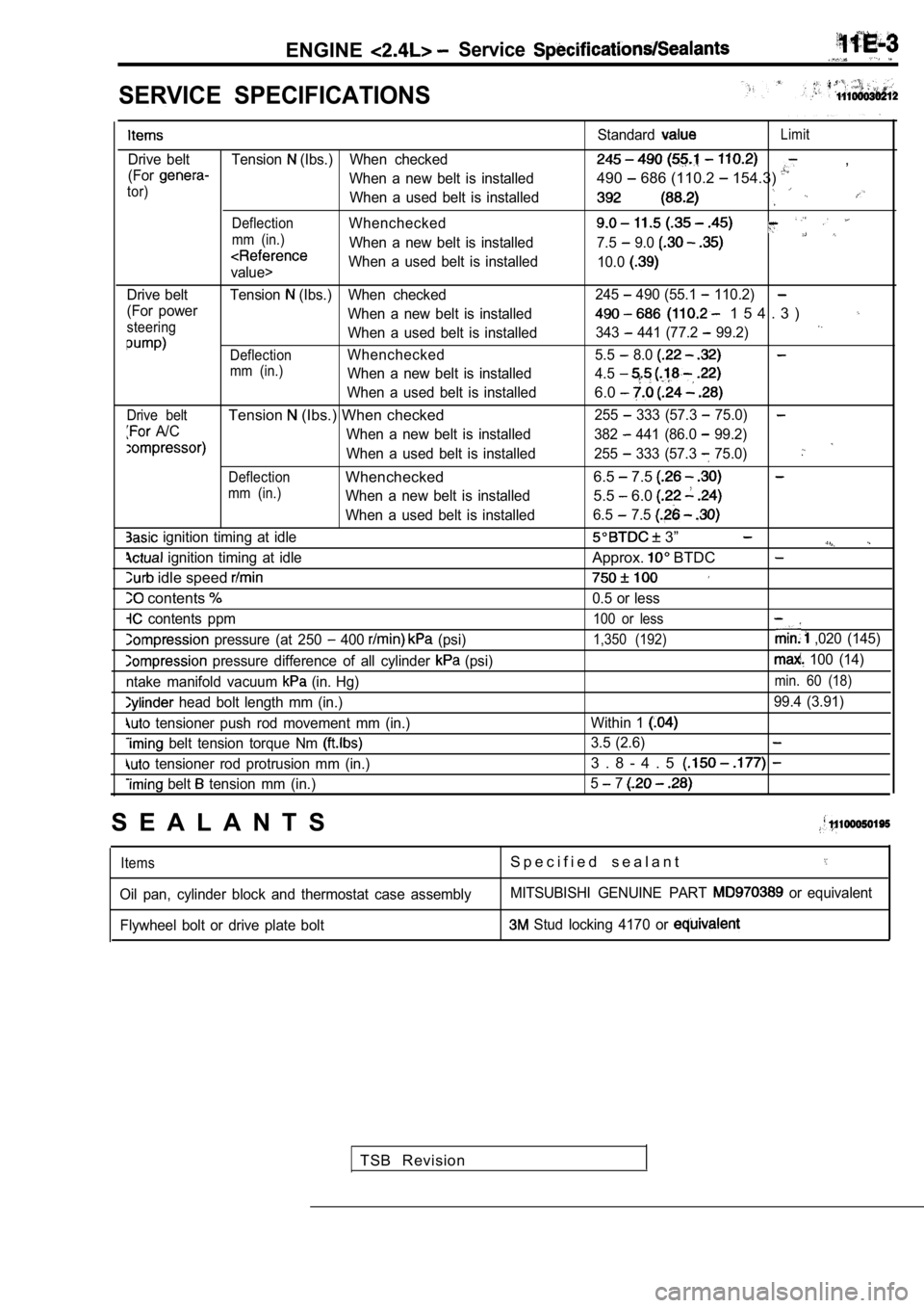
ENGINEService
SERVICE SPECIFICATIONS
Drive belt Tension (Ibs.) When checked
(For
When a new belt is installedtor)When a used belt is installed
DeflectionWhenchecked
mm (in.)When a new belt is installed
value> When a used belt is installed
Drive belt Tension
(Ibs.) When checked
(For power When a new belt is installed
steeringWhen a used belt is installed
DeflectionWhenchecked
mm (in.)When a new belt is installed
When a used belt is installed
Drive beltTension (Ibs.) When checked
A/C When a new belt is installed
When a used belt is installed
DeflectionWhenchecked
mm (in.)When a new belt is installed
When a used belt is installed
ignition timing at idle
ignition timing at idle
idle speed
contents
contents ppm
pressure (at 250 400 (psi)
pressure difference of all cylinder (psi)
ntake manifold vacuum
(in. Hg)
head bolt length mm (in.)
tensioner push rod movement mm (in.)
belt tension torque Nm
tensioner rod protrusion mm (in.)
belt tension mm (in.) Standard
Limit
,
490
686 (110.2 154.3)
7.5 9.0
10.0
245 490 (55.1 110.2)
1 5 4 . 3 )
343 441 (77.2 99.2)
5.5 8.0
4.5
6.0
255 333 (57.3 75.0)
382 441 (86.0 99.2)
255
333 (57.3 75.0)
6.5 7.5
5.5 6.0
6.5 7.5
3”
Approx. BTDC
0.5 or less
100 or less
1,350 (192) ,020 (145)
100 (14)
min. 60 (18)
99.4 (3.91)
Within 1
3.5 (2.6)
3 . 8 - 4 . 5
5 7
S E A L A N T S
ItemsS p e c i f i e d s e a l a n t
Oil pan, cylinder block and thermostat case assembl yMITSUBISHI GENUINE PART or equivalent
Flywheel bolt or drive plate bolt
Stud locking 4170 or
TSB Revision