1990 MITSUBISHI SPYDER air condition
[x] Cancel search: air conditionPage 8 of 2103
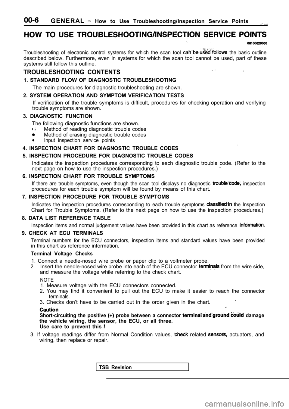
G E N E R A L How to Use Troubleshooting/Inspection Service Points
Troubleshooting of electronic control systems for which the scan tool the basic outline
described below. Furthermore, even in systems for w hich the scan tool cannot be used, part of these
systems still follow this outline.
TROUBLESHOOTING CONTENTS
1. STANDARD FLOW OF DIAGNOSTIC TROUBLESHOOTING
The main procedures for diagnostic troubleshooting are shown.
2. SYSTEM OPERATION AND SYMPTOM VERIFICATION TESTS If verification of the trouble symptoms is difficul t, procedures for checking operation and verifying
trouble symptoms are shown.
3. DIAGNOSTIC FUNCTION The following diagnostic functions are shown.
l ,Method of reading diagnostic trouble codes
Method of erasing diagnostic trouble codes
lInput inspection service points
4. INSPECTION CHART FOR DIAGNOSTIC TROUBLE CODES
5. INSPECTION PROCEDURE FOR DIAGNOSTIC TROUBLE CODE S
Indicates the inspection procedures corresponding t o each diagnostic trouble code. (Refer to the
next page on how to use the inspection procedures.)
6. INSPECTION CHART FOR TROUBLE SYMPTOMS
If there are trouble symptoms, even though the scan tool displays no diagnostic inspection
procedures for each trouble symptom will be found b y means of this chart.
7. INSPECTION PROCEDURE FOR TROUBLE SYMPTOMS
Indicates the inspection procedures corresponding t o each trouble symptoms the Inspection
Chart for Trouble Symptoms. (Refer to the next page on how to use the inspection procedures.)
8. DATA LIST REFERENCE TABLE
Inspection items and normal judgement values have b een provided in this chart as reference
9. CHECK AT ECU TERMINALS
Terminal numbers for the ECU connectors, inspection items and standard values have been provided
in this chart as reference information.
Terminal Voltage Checks
1. Connect a needle-nosed wire probe or paper clip to a voltmeter probe.
2.Insert the needle-nosed wire probe into each of the ECU connector from the wire side,
and measure the voltage while referring to the chec k chart.
NOTE
1. Measure voltage with the ECU connectors connecte d.
2. You may find it convenient to pull out the ECU t o make it easier to reach the connector
terminals.
3. Checks don’t have to be carried out in the order given in the chart.
Short-circuiting the positive probe between a connector damage
the vehicle wiring, the sensor, the ECU, or all thr ee.
Use care to prevent this
3. If voltage readings differ from Normal Condition values, related actuators, and
wiring, then replace or repair.
TSB Revision
Page 9 of 2103
GENERAL How to Use Troubleshooting/Inspection Service Points
4.After repair or replacement, recheck the voltmeter to confirm the repair
the problem.
Terminal Resistance and Continuity Checks
1. Turn the ignition switch to off.
2. Disconnect the ECU connector.
3.Measure the resistance and check for continuity bet ween the terminals of the ECU
connector while referring to the check chart.
NOTE
Checks don’t have to be carried out in the order gi ven in the chart.
Cautlon
If resistance and continuity checks are performed the wrong terminals, damage
vehicle wiring, sensors, ECU, and/or ohmmeter may o ccur.
Use care to prevent this!
4.If the ohmmeter shows any deviation from the Normal Condition value, check the corresponding
5.
sensor, actuator and related electrical wiring, then repair or replace.
After repair or replacement, recheck with the ohmme ter to confirm that the repair
the problem.
10. INSPECTION PROCEDURES USING AN OSCILLOSCOPE
When there are inspection procedures using an oscil loscope, these are listed here.
,
TSB Revision
Page 13 of 2103
G E N E R A L How to Use __
HOW TO COPE WITH INTERMITTENT
Most intermittent malfunctions occur under certain conditions. If those conditions can be identified, the
cause will be easier to find.
TO COPE WITH INTERMITTENT MALFUNCTION;1. Ask the customer about the malfunction
Ask what it feels
it sounds like, etc.
Then ask about
conditions; weather,
frequency of occurrence, and so on.
2.Determine the from the custom-
er’s responses
Typically, almost all intermittent malfunctions
occur from conditions like vibration, tempera-
ture and/or moisture change, poor connections.
From the customer’s replies, it should be rea-
soned which condition is influenced.
3. Use simulation test In the cases of vibration or poor connections,
use the simulation tests below to attempt to
duplicate the customer’s complaint. Determine
the most likely circuit(s) and perform
tion tests on the connectors and parts of that
circuit(s). Be sure to use the inspection proce-
dures provided for trouble codes
a n d t r o u b l e s y m p t o m s .
For temperature and/or moisture conditions re-
lated intermittent malfunctions, using common
sense, try to change the of
circuit components, then use
tion tests below,
4. Verify the intermittent malfunction is elimi-
nated
Repair the malfunctioning part and try to
the condition(s) again to verify the intermit-
tent malfunction has been eliminated.
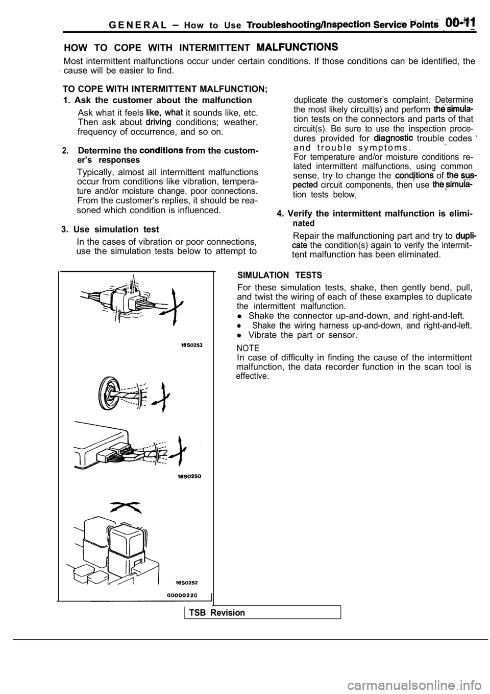
SIMULATION TESTS
For these simulation tests, shake, then gently bend , pull,
and twist the wiring of each of these examples to d uplicate
the intermittent malfunction.
l Shake the connector up-and-down, and right-and-left .
lShake the wiring harness up-and-down, and right-and -left.
l Vibrate the part or sensor.
NOTE
In case of difficulty in finding the cause of the i ntermittent
malfunction, the data recorder function in the scan tool is
effective.
TSB Revision
Page 48 of 2103
GENERAL Maintenance
4.Before removing dipstick, wipe all dirt from area around
dipstick. Then take out the dipstick and check the condition
of the fluid.
Further investigation of the transaxle is necessary if,
l the fluid smells burnt.
l the fluid color is brown or black.
l metal particles can be seen or felt on the dipstick .
5.Check to see if fluid level is in “HOT” range on dipstick.
If fluid level is low, add ATF until level reaches “HOT”
range. Low fluid level can cause a variety of condi tions
because it allows pump to take in air along with fl uid.
Air trapped in hydraulic circuit forms bubbles which make
fluid spongy.
Therefore, pressures will be erratic. Improper filling can also raise fluid level too hig h. When
transaxle has too much fluid, gears churn up foam a nd
cause same conditions which occur with low fluid le vel,
resulting in accelerated deterioration of ATF.
In either case, air bubbles can cause overheating, fluid
-oxidation, which can interfere with normal valve, clutch,
and servo operation. Foaming can also result in flu id
escaping from transaxle vent where it may be mistak en
for a leak.
6. Be sure to examine fluid on dipstick closely.
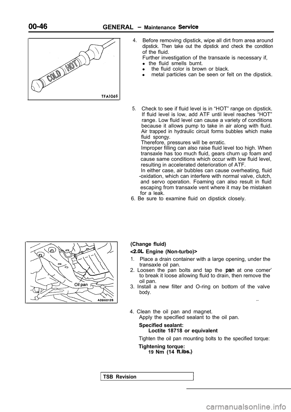
(Change fluid)
Engine (Non-turbo)>
1.Place a drain container with a large opening, under the
transaxle oil pan.
2. Loosen the pan bolts and tap the
at one comer’
to break it loose allowing fluid to drain, then rem ove the
oil pan.
3. Install a new filter and O-ring on bottom of the valve
body.
4. Clean the oil pan and magnet.
Apply the specified sealant to the oil pan.
Specified sealant: Loctite 18718 or equivalent
Tighten the oil pan mounting bolts to the specified torque:
Tightening torque:
19Nm (14
TSB Revision
Page 70 of 2103
ENGINE On-vehicle Service
NOTE
1.Ignition timing is variable within about even under
operating.
2. And it is automatically further advanced by abou t
from BTDC at higher altitudes.
CURB IDLE SPEED CHECK
1. Before inspection and adjustment, set vehicles in the
following condition.
lEngine coolant temperature:
lLights, electric cooling fan and all accessories: OFF
lTransaxle: Neutral (P range on vehicles with
2. Turn the ignition switch to OFF and connect the scan
tool to the data link connector.
3. Select No. 17 of the SCAN TOOL ACTUATOR TEST.
4. Check the basic ignition timing.
Standard
BTDC
5. Run the engine at idle for 2 minutes.
6. Select No. 22 of the SCAN TOOL DATA LIST.
7. Check the curb idle speed.
Standard value: 750
100
NOTE
The idle speed is controlled automatically by the i dle air
control system.
8. If the idle speed is outside the standard value, inspect
the components by referring to GROUP Trou-
bleshooting.
IDLE MIXTURE CHECK .
1.Before inspection, set in following
lEngine coolant temperature:
lLights, electric cooling fan all
lTransaxle: Neutral (P range on
2. Turn the ignition switch to OFF and, connect the scan
tool to the data link ,
3. Select No. 17 of the SCAN TOOL
4.Check that the basic ignition
value.
Standard value: BTDC
5. Run the engine 2,500 for 2 minutes.
6. Set the CO, HC tester.
7. Check the CO contents and the HC contents, at id le.
Standard value: CO contents: 0.5% or less
HC contents: 100 rpm or less
Revision
Page 73 of 2103
ENGINE On-vehicle Service
MANIFOLD VACUUM CHECK11100270200
1.Before inspection, set vehicles in the following condition:
lEngine coolant temperature:
lLights, electric cooling fan, and accessories: OFF
l Transaxle: Neutral (P range on vehicles with
2. Set up the tachometer or connect the scan tool t o the
data link connector.
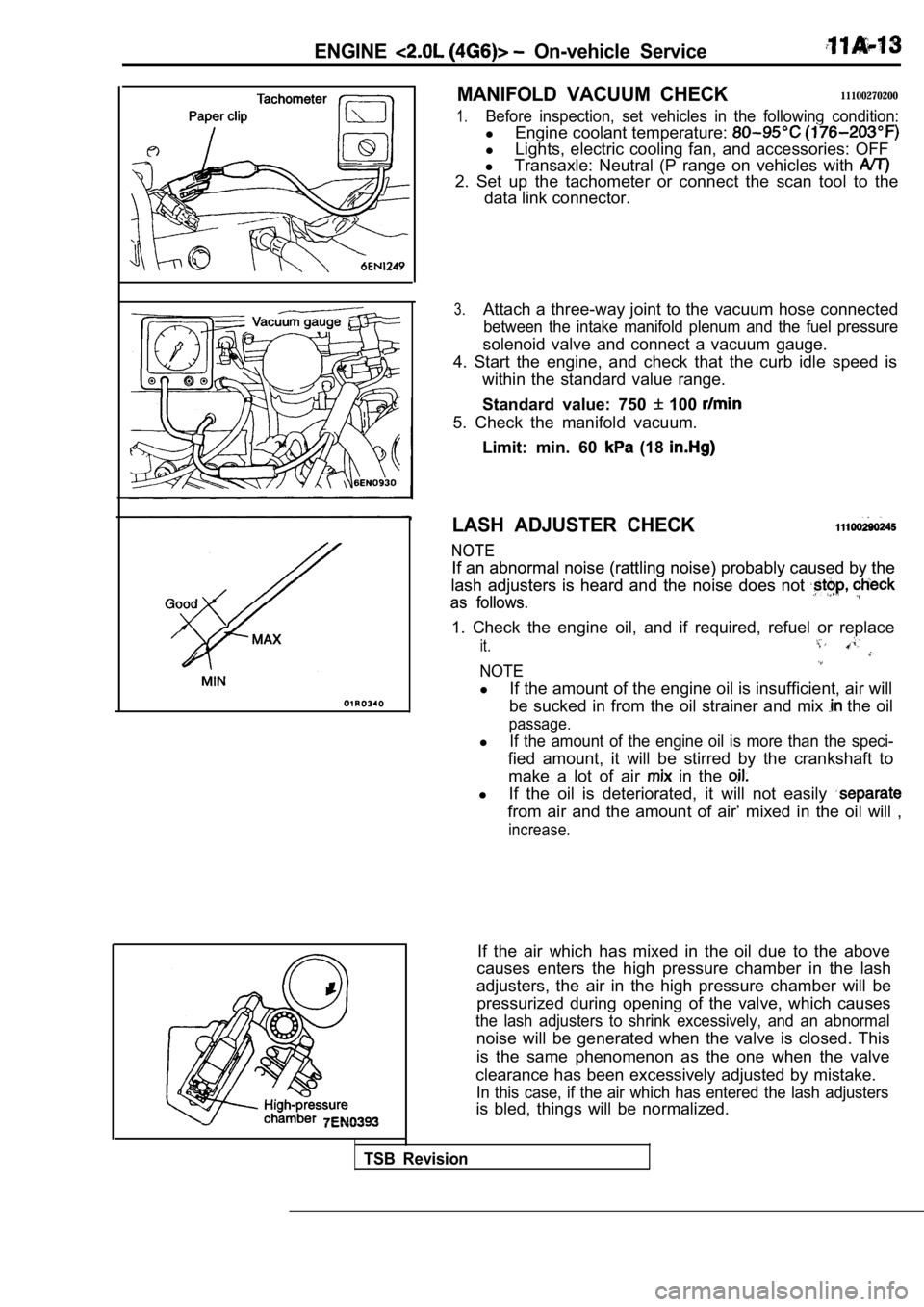
3.Attach a three-way joint to the vacuum hose connect ed
between the intake manifold plenum and the fuel pressure
solenoid valve and connect a vacuum gauge.
4. Start the engine, and check that the curb idle s peed is
within the standard value range.
Standard value: 750
100
5. Check the manifold vacuum.
Limit: min. 60
(18
LASH ADJUSTER CHECK
NOTE
NOTE
If an abnormal noise (rattling noise) probably caus ed by the
If an abnormal noise (rattling noise) probably caus ed by the
lash adjusters is heard and the noise does not
lash adjusters is heard and the noise does not
as follows.
as follows.
1. Check the engine oil, and if required, refuel or replace
it.
NOTE
lIf the amount of the engine oil is insufficient, ai r will
be sucked in from the oil strainer and mix
the oil
passage.
lIf the amount of the engine oil is more than the sp eci-
fied amount, it will be stirred by the crankshaft to
make a lot of air
in the
l If the oil is deteriorated, it will not easily
from air and the amount of air’ mixed in the oil wi ll ,
increase.
If the air which has mixed in the oil due to the ab ove
causes enters the high pressure chamber in the lash
adjusters, the air in the high pressure chamber wil l be
pressurized during opening of the valve, which caus es
the lash adjusters to shrink excessively, and an abnormal
noise will be generated when the valve is closed. T his
is the same phenomenon as the one when the valve
clearance has been excessively adjusted by mistake.
In this case, if the air which has entered the lash adjusters
is bled, things will be normalized.
TSB Revision
Page 77 of 2103
ENGINE Engine Assembly
4.9
29
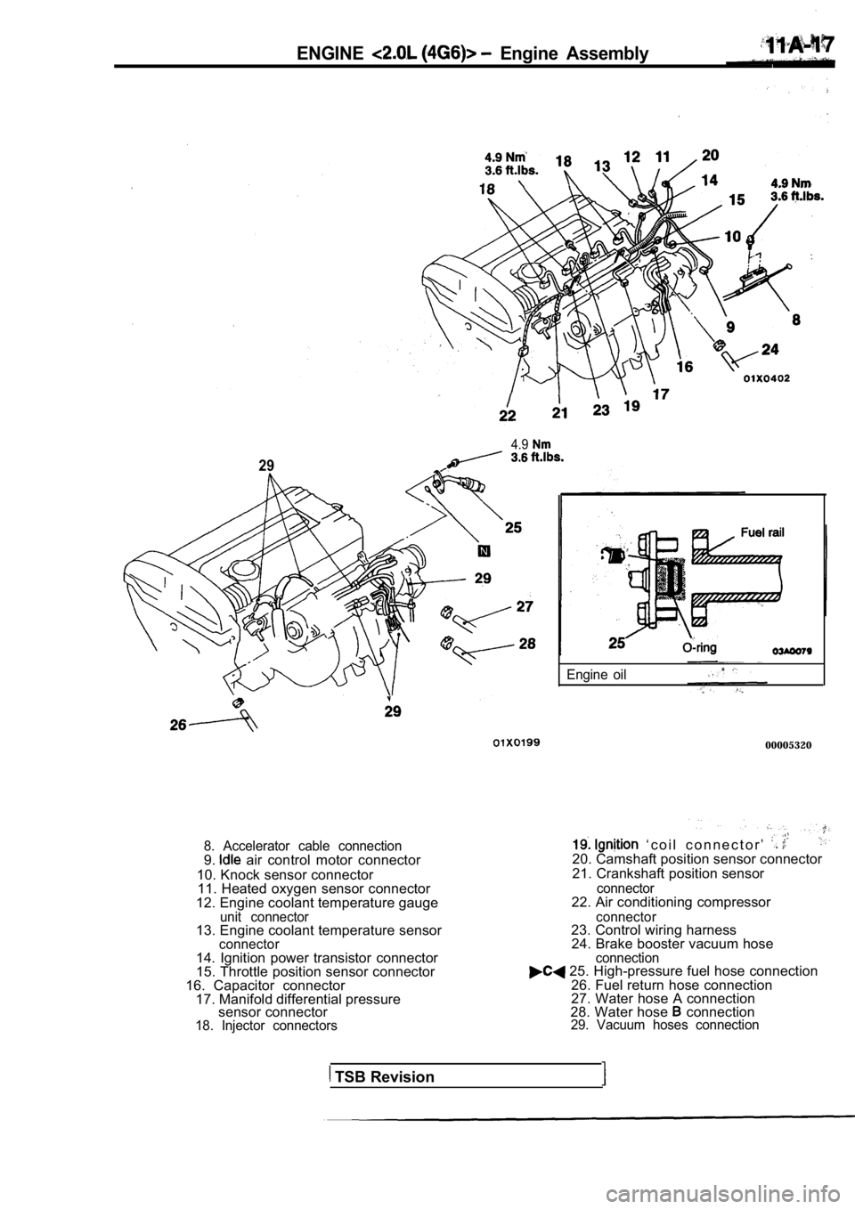
8. Accelerator cable connection9. air control motor connector
10. Knock sensor connector 11. Heated oxygen sensor connector
12. Engine coolant temperature gauge
unit connector13. Engine coolant temperature sensorconnector
Engine oil
00005320
‘ c o i l c o n n e c t o r ’ 20. Camshaft position sensor connector
21. Crankshaft position sensor
connector22. Air conditioning compressor
connector23. Control wiring harness 24. Brake booster vacuum hose .
14. Ignition power transistor connector
15. Throttle position sensor connector
16. Capacitor connector 17. Manifold differential pressure sensor connector
18. Injector connectors connection
25. High-pressure fuel hose connection
26. Fuel return hose connection
27. Water hose A connection
28. Water hose
connection29. Vacuum hoses connection
TSB Revision
Page 91 of 2103
ENGINE Cylinder Head
CYLINDER HEAD GASKET
REMOVAL AND INSTALLATION
Pre-removal Operationl Fuel Line Inner Pressure Release(Refer to GROUP On-vehiclel Engine Coolant Draining(Refer to GROUP 00 Maintenance Service.)l Engine Oil Draining(Refer to GROUP 00 Maintenance Service.)
3.62.9 Nm
2.2
4.9 Nm
220 1
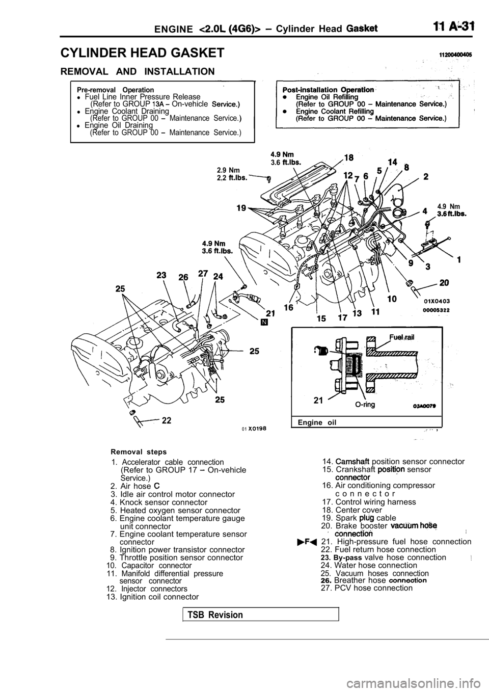
Removal steps
1. Accelerator cable connection(Refer to GROUP 17 On-vehicleService.)2. Air hose 3. Idle air control motor connector
4. Knock sensor connector
5. Heated oxygen sensor connector
6. Engine coolant temperature gauge
unit connector
7. Engine coolant temperature sensor
connector8. Ignition power transistor connector
9. Throttle position sensor connector
10. Capacitor connector
11. Manifold differential pressure sensor connector
12. Injector connectors
13. Ignition coil connector Engine oil
,
21
14. position sensor connector
15. Crankshaft sensor
16. Air conditioning compressor
c o n n e c t o r
17. Control wiring harness
18. Center cover
19. Spark
cable
20. Brake booster
21. High-pressure fuel hose connection 22. Fuel return hose connection
23. By-pass valve hose connection
24. Water hose connection25. Vacuum hoses connection26.Breather hose 27. PCV hose connection
TSB Revision