Page 838 of 2103
21CLUTCH Clutch Pedal
CLUTCH PEDAL
REMOVAL AND INSTALLATION
Pre-removal OperationlScuff Plate Removal GROUP Cowl Side Trim Removal(Refer to GROUP Trims.)
l Junction Block Installation Boll: Removal
Post-installation Operationl Clutch Pedal Adjustment (Refer tol Junction Block Installation
l Cowl Side Trim Installation (Refer to GROUP Trims.) Scuff Plate Installation
(Refer to GROUP Trims.)
I
I
Nm7-929 Nm21
5
Removal steps
1. Instrument under
(Refer to GROUP Panel.)
2. Master cylinder installation nuts
3. Clutch pedal return spring gine (Non-turbo) Engine>4. Clevis pin
5. Clutch pedal assembly
6. Clevis pin
(Turbo)>
7. Rod A Engine (Turbo)>
8. Turnover spring Engine
9. Rod Engine (Turbo)>
Revision
00003519
E n g i n e ( T u r b o ) >
Clutch pedal13. Bushing
14. Spacer
15. Pedal pad
16. Adjusting bolt
17. Clutch pedal position switch
18. Interlock switch
19. Clutch pedal bracket assembly
Page 1623 of 2103

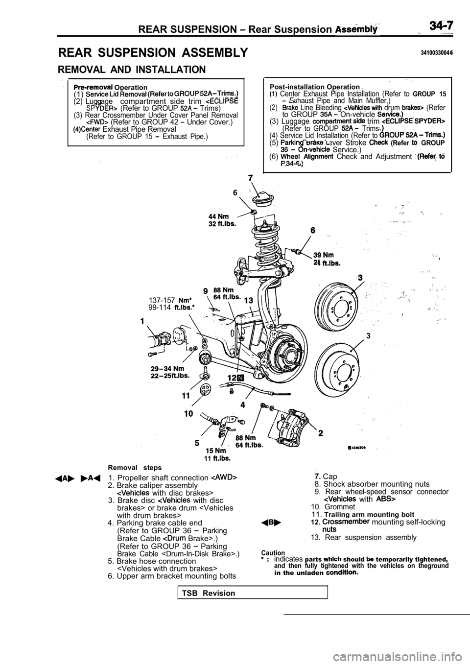
REAR SUSPENSION Rear Suspension
REAR SUSPENSION ASSEMBLY
REMOVAL AND INSTALLATION
Operation
(1)
(2) Lug agecompartment side trim SP (Refer to GROUP Trims)(3) Rear Crossmember Under Cover Panel Removal (Refer to GROUP 42 Under Cover.) Exhaust Pipe Removal(Refer to GROUP 15 Exhaust Pipe.)
3410033004
Post-installation Operation Center Exhaust Pipe Installation (Refer to GROUP 15Exhaust Pipe and Main Muffler,)(2) Line Bleeding drum (Referto GROUP On-vehicle (3) Luggage trim (Refer to GROUP Trims.
(4) Service Lid Installation (Refer to
(5) Brake Lever Stroke (Refer GROUP Service.)
(6) Check and Adjustment .
6
,
137-15799-114
.
l. .
3
Removal steps
11
1. Propeller shaft connection 2. Brake caliper assembly with disc brakes>
3. Brake disc with disc
brakes> or brake drum
with drum brakes>
4. Parking brake cable end
(Refer to GROUP 36
ParkingBrake Cable Brake>.)
(Refer to GROUP 36
ParkingBrake Cable .)5. Brake hose connection
6. Upper arm bracket mounting bolts
Cap
8. Shock absorber mounting nuts
9. Rear wheel-speed sensor connector with 10. Grommet11. Trailing arm mounting bolt
12. mounting self-locking
13. Rear suspension assembly
Cautionindicatesparts should temporarily tightened,and then fully tightened with the vehicles on thegr oundin the unladen
TSB Revision
Page 1761 of 2103
REMOVAL AND INSTALLATION
Pre-removal and Post-installation OperationlCowl Side Trim (R.H.), Front Scuff Plate Removaland Installation (Refer to GROUP Trims.)
Removalsteps
Control unit cover
2. ABS-ECU
INSPECTION
ABS-ECU CHECK
Refer to
TSBRevision
Page 1834 of 2103

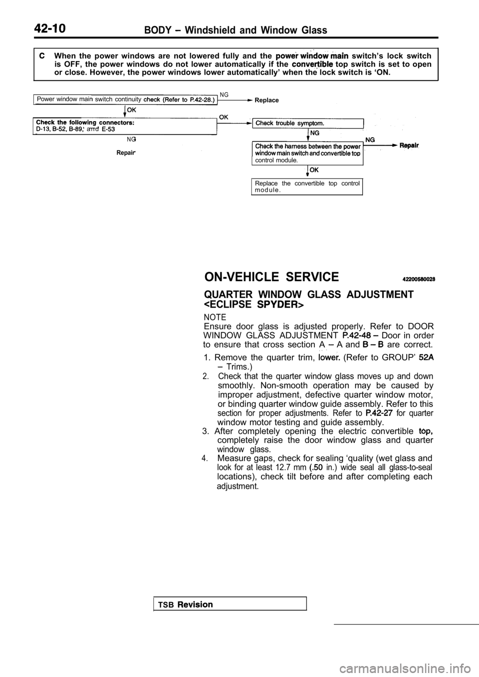
BODY Windshield and Window Glass
When the power windows are not lowered fully and the switch’s lock switch
is OFF, the power windows do not lower automaticall y if the
top switch is set to open
or close. However, the power windows lower automati cally’ when the lock switch is ‘ON.
Power window mair
switch continuity NG Replace
a n d
N G
Repaircontrol module.
Replace the convertible top control
m o d u l e .
ON-VEHICLE SERVICE
QUARTER WINDOW GLASS ADJUSTMENT
NOTE
Ensure door glass is adjusted properly. Refer to DO OR
WINDOW GLASS ADJUSTMENT
Door in order
to ensure that cross section A
A and are correct.
1. Remove the quarter trim,
(Refer to GROUP’
Trims.)
2.Check that the quarter window glass moves up and do wn
smoothly. Non-smooth operation may be caused by
improper adjustment, defective quarter window motor ,
or binding quarter window guide assembly. Refer to this
section for proper adjustments. Refer to for quarter
window motor testing and guide assembly.
3. After completely opening the electric convertibl e
completely raise the door window glass and quarter
window glass.
4.Measure gaps, check for sealing ‘quality (wet glass and
look for at least 12.7 mm in.) wide seal all glass-to-seal
locations), check tilt before and after completing each
adjustment.
TSB
Page 1839 of 2103

BODY Windshield and Window
SlitRear rail
ail weath
window0 0 0 0 4 8 1 1 12. Close the convertible top
quarter window glass enters the slit on the rear ra
il
weatherstrip
when the quarter windows are
Recheck all measurements. Adjustment to any of
adjusting deviceswill affect other settings.
14. Check for sealing quality (wet glass and look f or least
12.7 mm in.) wide seal all glass-to-seal locations.)
15. Install the quarter trim,lower (Refer to GROUP
Trims.)
,
WINDSHIELD AND WINDOW GLASS
GENERAL. .
The windshield and window glass are attached by a urethane-base adhesive, to the window -frame.
This adhesive not only improved glass holding and sealing, but also permi ts use of body openings
having a greater structural strength.
ADHESIVE
Adhesive kit QuantityI
ATD Part No. 8609 SUPER FAST URETHANEOne cartridge
ATD Part No. 8608 SUPER FAST URETHANE PRIMER
As required
RESERVE ITEMS
Items
Wire length)
Adhesive gun
Wiping rags
Sealer
ATD Part or eauivalent
Glass holder
Spacers (Service part)
Window molding (Service part) Dam (Service part)
(Valvoline Oil Company)
,
Applications Quantity
For cutting adhesive Five pieces of wire
0.6 mmx
in. 3.3 ft.)
For adhesive application One
As required
For prevention of water leaks andAs required
gathering after adhesive application
For
As required
T w o
As required
One
As required
As required
TSB Revision
Page 1841 of 2103
BODY Windshield and’ . ..
WINDSHIELD
REMOVAL AND INSTALLATION.
and Post-installation OperationRemoval and Installationl Front Deck Garnish(Refer to GROUP 51 Garnishes.)lFront Pillar Trim (Refer to GROUP Trims.)lHeadlining (Refer to GROUP Headlining.)
Section A-A
molding
mm (in.)
Section B-B
Section C-C
mm (in.)
Adhesive:
ATD Part No. 8609 Super Fast Urethane ATD Super Fast Urethane Primer or equivalent
Removal steps
1. Windshield 4. Window spacer
2. Windshield molding5. Window spacer
3. Window spacer 6. Dual-lock fastener
TSB Revision
Page 1850 of 2103
BODY Windshield and Window Glass
QUARTER WINDOW GLASS AND REGULATOR ASSEMBLY
REMOVAL AND INSTALLATION
IPost-installation OperationQuarter Window Glass Adjustment (Refer to I
122820
Power window switch removalsteps
1. Door trims (Refer to GROUP 42 Door.)2. Power window switch
Quarter window glass removalsteps
l Quarter trim, lower
(Refer to GROUP Trims.) Quarter belt moulding (Refer to GROUP
3. Quarter trim bracket
4. Quarter belt line inner weatherstrip
and quarter window front weather-
strip
5. Waterproof film
window glass assembly
Quarter window glass
9. Guide assembly
Regulator assembly removal steps
6. Quarter window glass assembly l Rear speaker bracket A
(Refer to GROUP 54 Speaker.)10. Regulator assembly
TSB Revision
Page 1853 of 2103
BODY Windshield. and Window
REMOVAL AND INSTALLATION
Pre-removal and Post-installation Operation
Removal and Installation
l Rear Wiper Arm(Refer to GROUP 51 Rear Wiper and Washer.)l Upper Trim, Lower Trim and Side Trim (Refer to GROUP Trims.)l High-mounted Stop Light without rearspoiler, (Refer to GROUP 54 High-mounted Stop
Light.)
Adhesive tape:
or equivalent
Section C-C24
Section
Section D-D
mm (in.). .
Adhesive:
ATD Part No. Super Fast Urethane and ATD Part No. 8608 Super Fast Urethane prim& equivalent
Removal steps
Harness connector 3. m o l d i n g
2. g l a s s Dual-lock fasteners
TSB Revision