1990 MITSUBISHI SPYDER height
[x] Cancel search: heightPage 29 of 2103
GENERAL Special Handling Instructions for Models
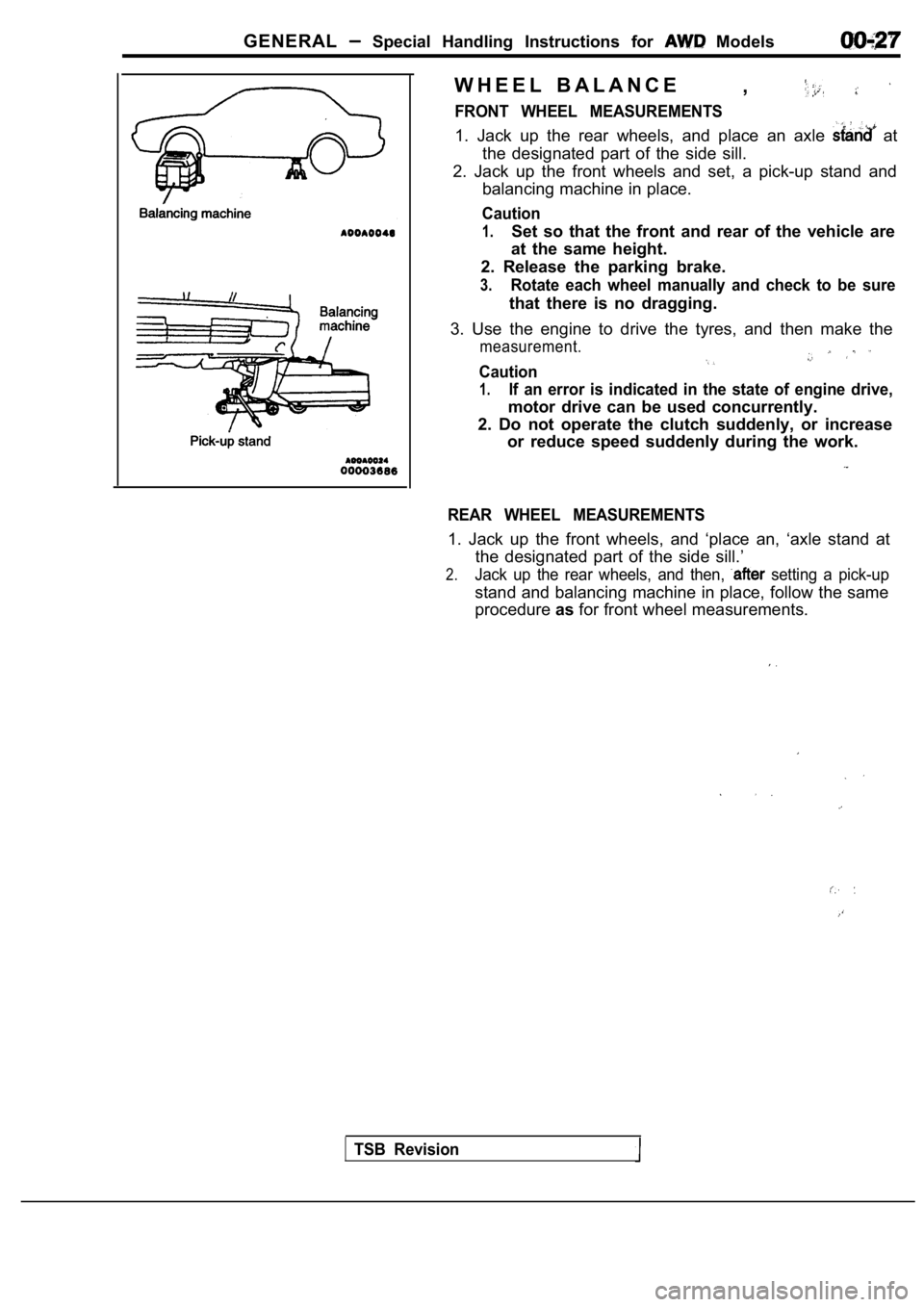
W H E E L B A L A N C E,
FRONT WHEEL MEASUREMENTS
1. Jack up the rear wheels, and place an axle at
the designated part of the side sill.
2. Jack up the front wheels and set, a pick-up stan d and
balancing machine in place.
Caution
1.Set so that the front and rear of the vehicle are
at the same height.
2. Release the parking brake.
3.Rotate each wheel manually and check to be sure
that there is no dragging.
3. Use the engine to drive the tyres, and then make the
measurement.
Caution
1.If an error is indicated in the state of engine drive,
motor drive can be used concurrently.
2. Do not operate the clutch suddenly, or increase or reduce speed suddenly during the work.
REAR WHEEL MEASUREMENTS
1. Jack up the front wheels, and ‘place an, ‘axle s tand at
the designated part of the side sill.’
2.Jack up the rear wheels, and then, setting a pick-up
stand and balancing machine in place, follow the sa me
procedure asfor front wheel measurements.
TSB Revision
Page 30 of 2103
GENERAL General Data and Specifications“
00199999191
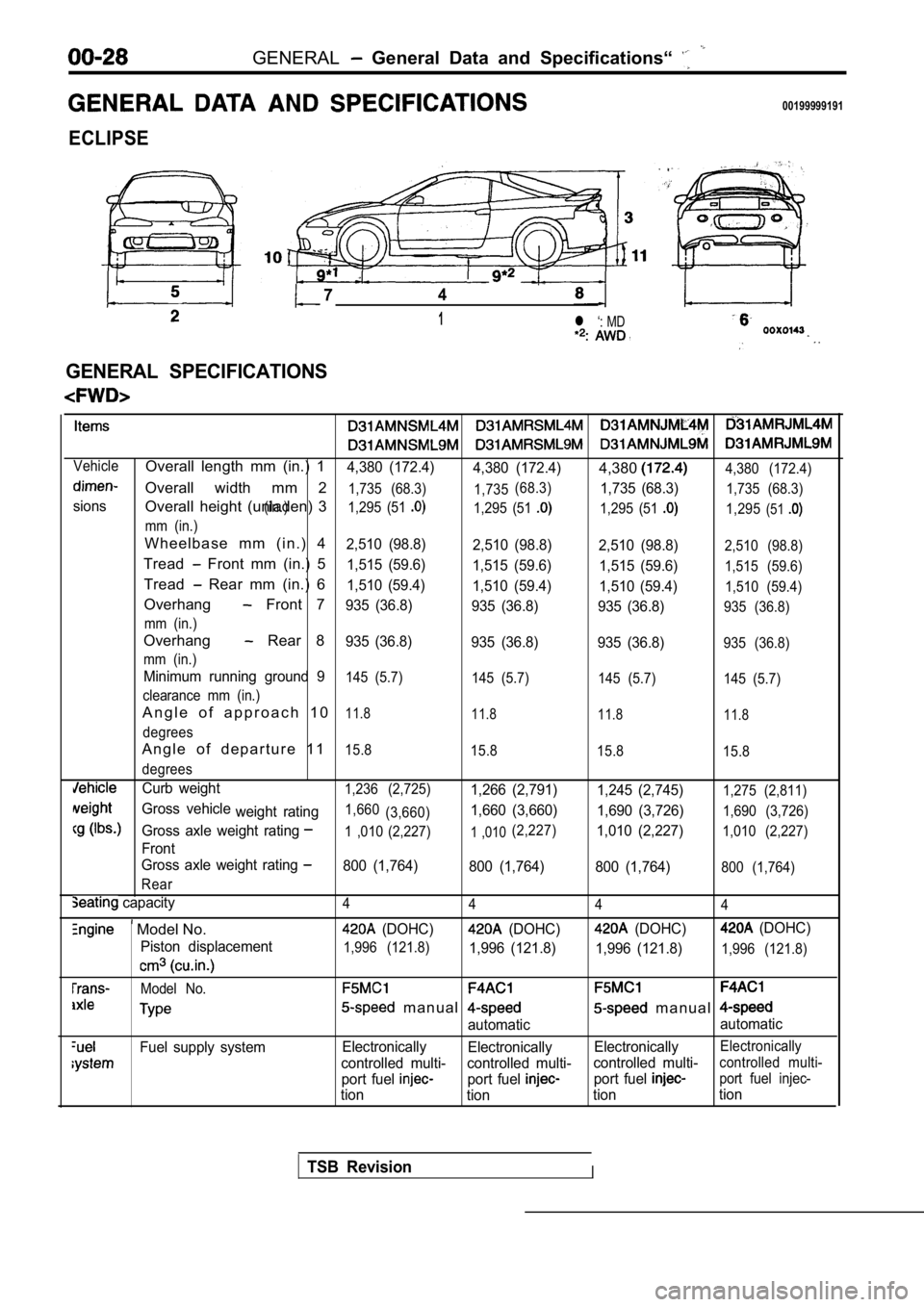
ECLIPSE
74
1l ‘: MD
.
GENERAL SPECIFICATIONS
VehicleOverall length mm (in.) 14,380 (172.4)4,380 (172.4)4,3804,380 (172.4)
Overall width mm 21,735 (68.3) 1,735
sions(in.) (68.3)
1,735 (68.3)1,735 (68.3)
Overall height (unladen) 31,295 (51 1,295 (51 1,295 (51 1,295(51
mm (in.)
W h e e l b a s e m m ( i n . ) 42,510 (98.8)
2,510 (98.8)2,510 (98.8)2,510 (98.8)
Tread Front mm (in.) 51,515 (59.6)
1,515 (59.6) 1,515 (59.6)1,515 (59.6)
Tread Rear mm (in.) 61,510 (59.4)
1,510 (59.4) 1,510 (59.4)1,510 (59.4)
Overhang Front 7935 (36.8)
935 (36.8) 935 (36.8)935 (36.8)
mm (in.)
Overhang Rear 8935 (36.8) 935 (36.8) 935 (36.8)935 (36.8)
mm (in.)
Minimum running ground 9145 (5.7) 145 (5.7) 145 (5.7)145 (5.7)
clearance mm (in.)
A n g l e o f a p p r o a c h 1 011.8 11.8 11.811.8
degrees
A n g l e o f d e p a r t u r e 1 115.8
15.8 15.815.8
degrees
Curb weight1,236 (2,725)1,266 (2,791) 1,245 (2,745)1,275 (2,811)
Gross vehicle
weight rating1,660(3,660)1,660 (3,660) 1,690 (3,726)1,690 (3,726)
Gross axle weight rating1 ,010 (2,227)1 ,010(2,227)1,010 (2,227)1,010 (2,227)
Front
Gross axle weight rating
800 (1,764) 800 (1,764) 800 (1,764)800 (1,764)
Rear
capacity4 4 44
Model No. (DOHC) (DOHC) (DOHC) (DOHC)
Piston displacement
1,996 (121.8)1,996 (121.8) 1,996 (121.8)1,996 (121.8)
Model No.
m a n u a l m a n u a l
automatic automatic
Fuel supply system
Electronically
Electronically ElectronicallyElectronically
controlled multi- controlled multi- controlled multi-controlled multi-
port fuel port fuel port fuel port fuel injec-
tion
tion tiontion
TSB RevisionI
Page 32 of 2103
GENERAL General and
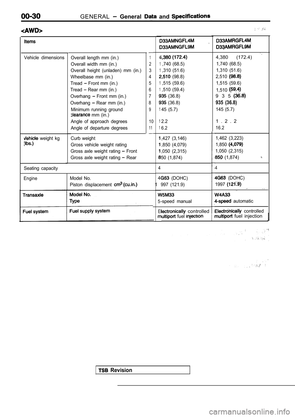
Vehicle dimensions
weight kg
Overall length mm (in.)
Overall width mm (in.)
Overall height (unladen) mm (in.)
Wheelbase mm (in.)
Tread
Front mm (in.)
Tread
Rear mm (in.)
Overhang
Front mm (in.)
Overhang
Rear mm (in.)
Minimum running ground
mm (in.)
Angle of approach degrees
Angle of departure degrees
Curb weight
Gross vehicle weight rating
Gross axle weight rating
Front
Gross axle weight rating
Rear
1
2
3
4 5
6
7
8
9
10
11
Seating capacity
EngineModel No.
Piston displacement
4
1,740 (68.5)
1,310 (51.6)
(98.8)
1,515 (59.6)
1,510 (59.4)
(36.8)
(36.8)
145 (5.7)
4,380 (172.4)
1,740 (68.5)
1,310 (51.6)
2,510
1,515 (59.6)
1,510
9 3 5
935 (36.8)
145 (5.7)
12.2
16.2
,427 (3,146)
,850 (4,079)
,050 (2,315)
50 (1,874)
4
4
1
5
El
1 . 2 . 2
16.2
1,462 (3,223)
1,850
1,050 (2,315)
(1,874)
4
(DOHC)
997 (121.9)
-speed manual
(DOHC)
1997
automatic
controlled controlled
fuel fuel injection
Revision
Page 33 of 2103
GENERAL General Data and Specifications
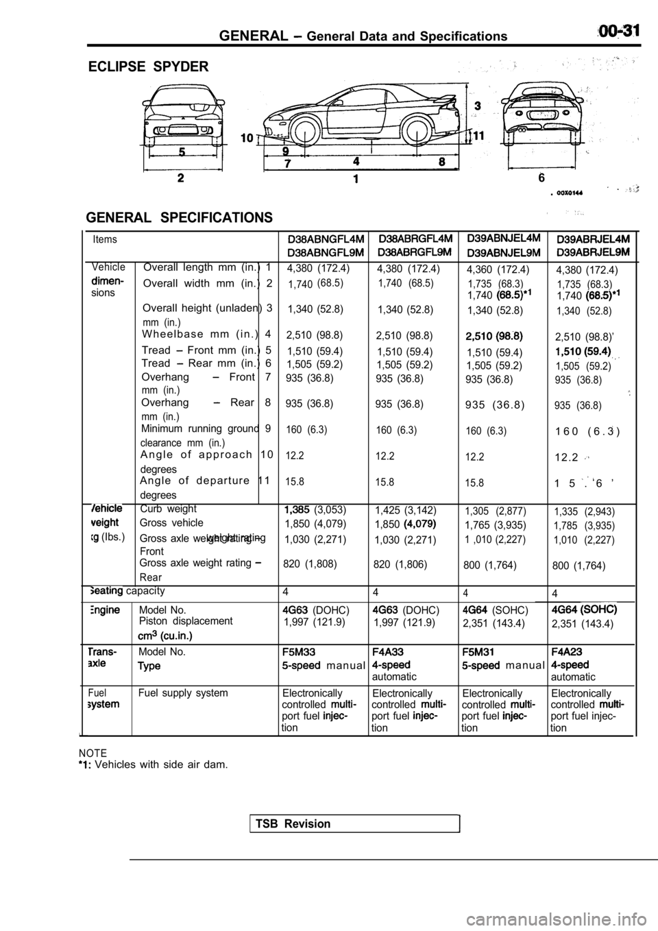
ECLIPSE SPYDER
GENERAL SPECIFICATIONS
6
.
Items
VehicleOverall length mm (in.) 14,380 (172.4) 4,380 (172.4)
4,360 (172.4)4,380 (172.4)
Overall width mm (in.) 21,740(68.5)
1,740 (68.5)
1,735 (68.3)1,7401,735 (68.3)sions
1,740
Overall height (unladen) 31,340 (52.8)1,340 (52.8)
1,340 (52.8)1,340 (52.8)
mm (in.)
W h e e l b a s e m m ( i n . ) 42,510 (98.8) 2,510 (98.8)2,510 (98.8)’
Tread Front mm (in.) 51,510 (59.4) 1,510 (59.4)
1,510 (59.4)
Tread Rear mm (in.) 61,505 (59.2) 1,505 (59.2)
1,505 (59.2)1,505 (59.2)Overhang Front 7935 (36.8) 935 (36.8)
935 (36.8)935 (36.8)
mm (in.)
Overhang Rear 8935 (36.8) 935 (36.8)9 3 5 ( 3 6 . 8 )935 (36.8)
mm (in.)
Minimum running ground 9160 (6.3) 160 (6.3)
160 (6.3)1 6 0 ( 6 . 3 )
clearance mm (in.)
A n g l e o f a p p r o a c h 1 012.2 12.2
12.21 2 . 2
degrees
A n g l e o f d e p a r t u r e 1 115.8 15.8
15.81 5 . 6 ’
degrees
Curb weight (3,053)1,425 (3,142)1,305 (2,877) 1,335 (2,943)
Gross vehicle
1,765 (3,935)1,785 (3,935)
(Ibs.)weight rating1,850 (4,079)
1,850Gross axle weight rating 1,030 (2,271)1,030 (2,271)1 ,010 (2,227) 1,010 (2,227)
Front
Gross axle weight rating
820 (1,808) 820 (1,806)
800 (1,764)800 (1,764)
Rear
capacity
Model No.
Piston displacement
Model No.
FuelFuel supply system
NOTE
Vehicles with side air dam. 4
444
(DOHC) (DOHC) (SOHC)
1,997 (121.9)
1,997 (121.9)
2,351 (143.4)2,351 (143.4)
m a n u a l m a n u a l
automatic automatic
Electronically Electronically Electronically Electronically
controlled
controlledcontrolledcontrolled
port fuel port fuel port fuel port fuel injec-
tion tion tion tion
TSB Revision
Page 107 of 2103
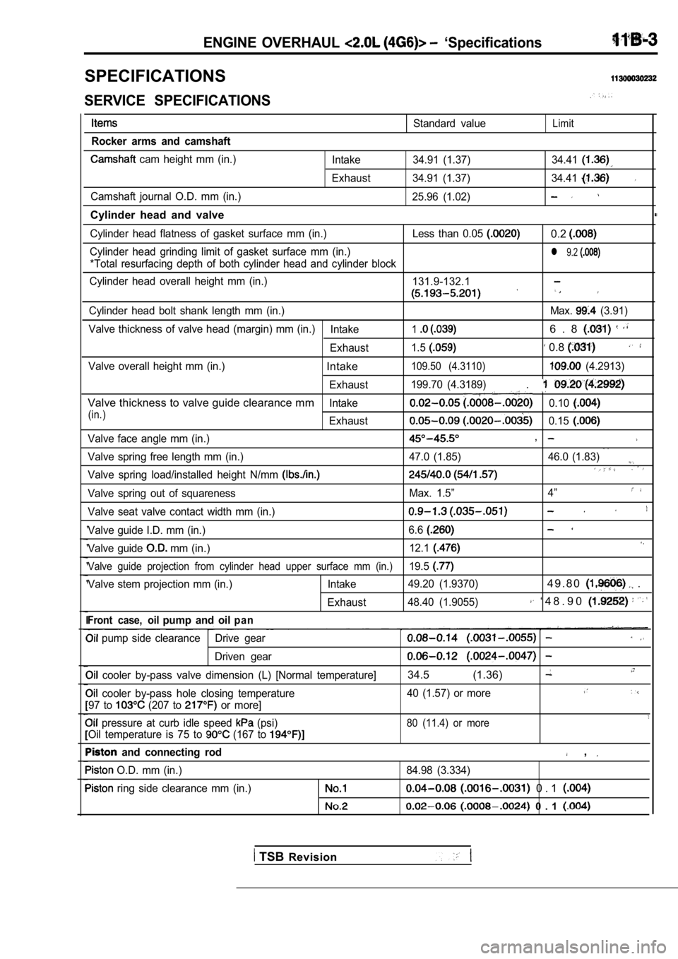
ENGINE OVERHAUL ‘Specifications
SPECIFICATIONS
SERVICE SPECIFICATIONS
Rocker arms and camshaft
cam height mm (in.)
Camshaft journal O.D. mm (in.)
Cylinder head and valve
Standard valueLimit
Intake 34.91 (1.37) 34.41
Exhaust 34.91 (1.37) 34.41
25.96 (1.02)
Cylinder head flatness of gasket surface mm (in.) Le ss than 0.05 0.2
Cylinder head grinding limit of gasket surface mm (in.)l 9.2
*Total resurfacing depth of both cylinder head and cylinder block
Cylinder head overall height mm (in.) 131.9-132.1
Cylinder head bolt shank length mm (in.) Max. (3.91)
Valve thickness of valve head (margin) mm (in.) Intake
16 . 8
Exhaust1.5 0.8
Valve overall height mm (in.)Intake109.50 (4.3110) (4.2913)
Exhaust 199.70 (4.3189)
.
Valve thickness to valve guide clearance mmIntake0.10
(in.)Exhaust0.15
Valve face angle mm (in.),
Valve spring free length mm (in.) 47.0 (1.85) 46.0 (1
.83)
Valve spring load/installed height N/mm
Valve spring out of squarenessMax. 1.5”4”
Valve seat valve contact width mm (in.)
Valve guide I.D. mm (in.) 6.6
Valve guide mm (in.)12.1
Valve guide projection from cylinder head upper sur
face mm (in.)19.5
Valve stem projection mm (in.) Intake 49.20 (1.9370)4 9 . 8 0 .
Exhaust48.40 (1.9055) ‘ 4 8 . 9 0
Front case, oilpump and oilp a n
pump side clearance Drive gear
Driven gear
cooler by-pass valve dimension (L) [Normal tempera
ture]34.5 (1.36)
cooler by-pass hole closing temperature 40 (1.57) or more
97 to (207 to or more]
pressure at curb idle speed (psi)80 (11.4) or more
Oil temperature is 75 to (167 to
and connecting rod ,
O.D. mm (in.)
84.98 (3.334)
ring side clearance mm (in.) 0 . 1
0 . 1
TSB Revision
Page 108 of 2103
![MITSUBISHI SPYDER 1990 Service Repair Manual ENGINE OVERHAUL
Items Standard value
Piston ring end gap mm (in.)
Piston pin O.D. mm (in.)
0 . 8
Oil 9 . 8
21
Piston pin press-in load (Ibs.)
[Room temperature]
Crankshaft pin MITSUBISHI SPYDER 1990 Service Repair Manual ENGINE OVERHAUL
Items Standard value
Piston ring end gap mm (in.)
Piston pin O.D. mm (in.)
0 . 8
Oil 9 . 8
21
Piston pin press-in load (Ibs.)
[Room temperature]
Crankshaft pin](/manual-img/19/57345/w960_57345-107.png)
ENGINE OVERHAUL
Items Standard value
Piston ring end gap mm (in.)
Piston pin O.D. mm (in.)
0 . 8
Oil 9 . 8
21
Piston pin press-in load (Ibs.)
[Room temperature]
Crankshaft pin oil clearance mm (in.) 17,500
Connecting rod big end side clearance mm (in.)
Crankshaft, flywheel and drive plate
Bearing cap bolt shank length mm (in.)
0 . 4
Crankshaft end play mm (in.)
Crankshaft journal O.D. mm (in.) 0 . 2 5
57 (2.24)
pin O.D. mm (in.) 42 (1.77)
Crankshaft journal oil clearance mm (in.)
to cylinder clearance mm (in.)
0 . 1
block flatness of gasket surface mm (in.) 0.05 0.1
block grinding limit of gasket surface mm (in.)l 0.2‘Total resurfacing depth of both cylinder head and cylinder block
block overall height mm (in.)283.9-284.1
(11.177-11.185)
block I.D. mm (in.) 85.0 (3.35)
TSBRevision
REWORK DIMENSIONS
Items
Cylinder head and valve
Oversize rework dimensions of valve guide0.05 O.S.
hole (both intake and exhaust) mm (in.) 0.25 O.S.
0.50
Intake oversize rework 0.3
dimensions of valve seat hole mm (in.)
0.6 O.S.
Exhaust oversize rework dimensions of valve 0.3 O.S.
seat hole
mm (in.)0.6 O.S.
Crankshaft, flywheel and drive plate
Crankshaft out of roundness and taper of journal an d pin mm (in.)
Standard value
12.25-12.27 ,
,
Max. 0.01
NOTE
O.D.: Outer diameter
I.D.: Inner diameter
Oversize diameter
Page 138 of 2103
11 ENGINE OVERHAUL Rocker
.
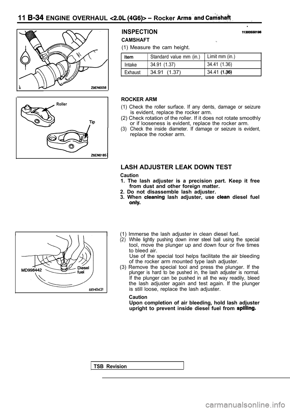
INSPECTION
CAMSHAFT
(1) Measure the cam height.
Roller
Standard value mm (in.)Limit mm (in.)
Intake 34.91 (1.37) 34.41 (1.36)
Exhaust
34.91 (1.37)34.41
ROCKER ARM
(1) Check the roller surface. If any dents, damage or seizure
is evident, replace the rocker arm.
(2) Check rotation of the roller. If it does not ro tate smoothly
or if looseness is evident, replace the rocker arm.
(3) Check the inside diameter. If damage or seizure is evident,
replace the rocker arm.
LASH ADJUSTER LEAK DOWN TEST
Caution
1. The lash adjuster is a precision part. Keep it f ree
from dust and other foreign matter.
2. Do not disassemble lash adjuster.
3. When
lash adjuster, use diesel fuel
(1) Immerse the lash adjuster in clean diesel fuel.
(2)While lightly pushing down inner steel ball using t he special
tool, move the plunger up and down four or five tim es
to bleed air. Use of the special tool helps facilitate the air bl eeding
of the rocker arm mounted type lash adjuster.
(3) Remove the special tool and press the plunger. If the
plunger is hard to be pushed in, the lash adjuster is normal.
If the plunger can be pushed in all the way readily, bleed
the lash adjuster again and test again. If the plun ger
is still loose, replace the lash adjuster.
Caution
Upon completion of air bleeding, hold lash adjuster
upright to prevent inside diesel fuel from
TSB Revision
Page 143 of 2103
ENGINE OVERHAUL Cylinder Head and
Valve seat
contact
Margin
I
I
Free
height
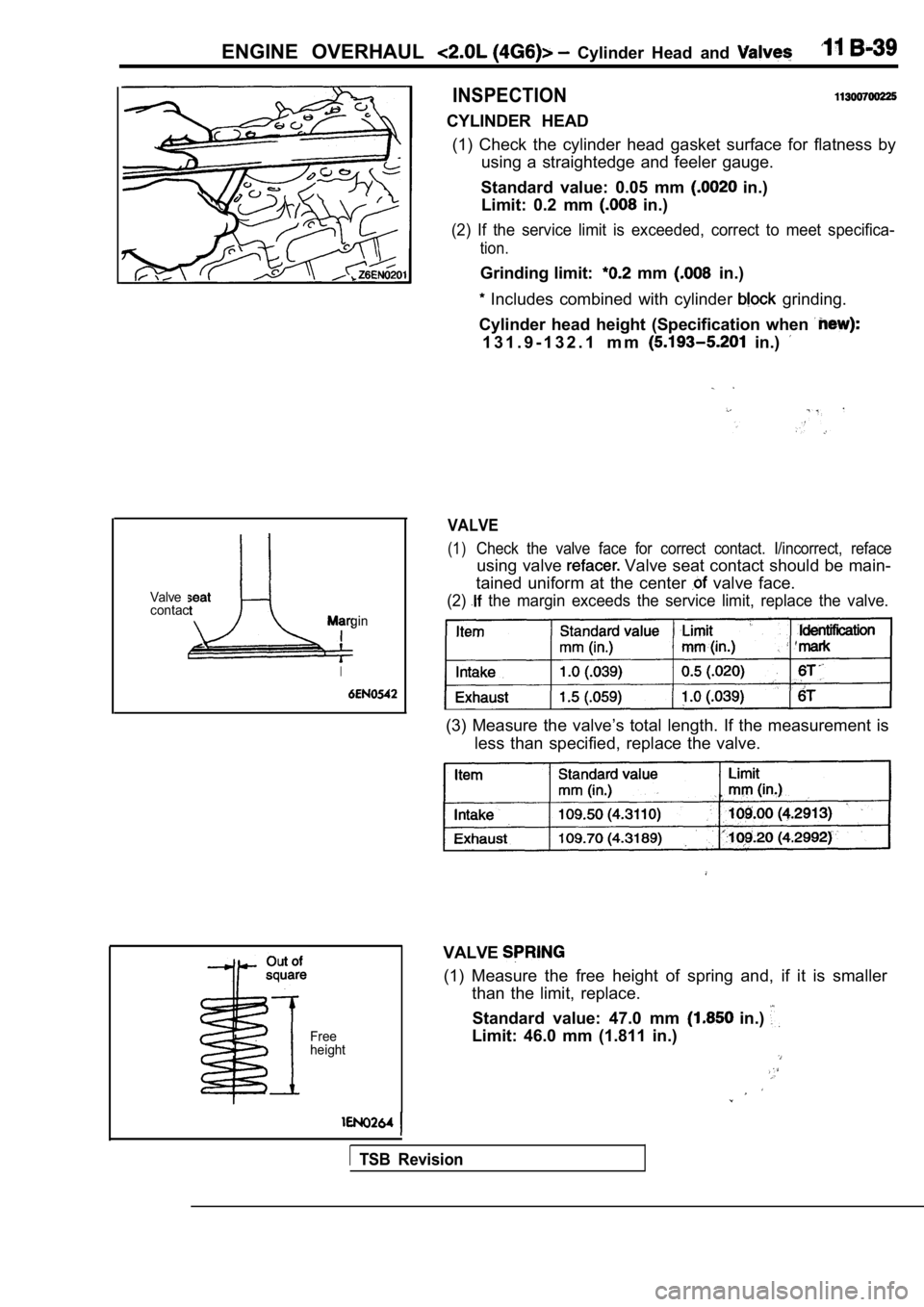
INSPECTION
CYLINDER HEAD (1) Check the cylinder head gasket surface for flat ness by
using a straightedge and feeler gauge.
Standard value: 0.05 mm
in.)
Limit: 0.2 mm
in.)
(2) If the service limit is exceeded, correct to me et specifica-
tion.
Grinding limit: mm in.)
Includes combined with cylinder grinding.
Cylinder head height (Specification when
1 3 1 . 9 - 1 3 2 . 1 m m in.)
VALVE
(1)Check the valve face for correct contact. I/incorre ct, reface
using valve Valve seat contact should be main-
tained uniform at the center
valve face.
(2) the margin exceeds the service limit, replace the valve.
(3) Measure the valve’s total length. If the measurement is
less than specified, replace the valve.
VALVE
(1) Measure the free height of spring and, if it is smaller
than the limit, replace.
Standard value: 47.0 mm
in.)
Limit: 46.0 mm (1.811 in.)
TSB Revision