Page 52 of 2103

GENERAL Maintenance Service
2.Check the wheel cylinder boots for evidence, a’ brake
fluid leak. Visually check the
boots for tears or
cracks. (A slight amount of fluid on the boot may not
be a leak, but may be preservative assembly.)
Caution
The shoes for the right and left be,
replaced at the same time.
Never split or intermix brake
sets.
All four shoes must be replaced as a set.
Thickness of lining
Limit: 1.0 mm in.)
17. BRAKE HOSES (Check for
leaks)
Check of brake hoses and tubing should be
brake service operations.
The hoses should be checked for:
1.Correct length, severe surface cracking, pulling, scuffing
or worn spots. (If the fabric casing of the hoses i s exposed
by cracks of abrasion in the rubber hose cover, the hoses
should be replaced. Eventual deterioration of may
occur with possible bursting failure.)
2. Faulty installation, casing twisting or interfer ence
wheel,’ tire or chassis.
18. BALL JOINT AND STEERING SEALS
(Check for grease leaks damage)
1. These components, which are permanently lubricat ed
at the factory, do not require periodic lubrication. Damaged
seals and boots should be replaced to prevent leakage
or contamination of the grease.
2.Check the dust cover and boots for proper sealing, leakage
and damage. Replace them if defective.
19. DRIVE SHAFT BOOTS (Check for leaks
and damage)
1. These components, which are permanently lubricat ed
at the factory, do not require periodic Damaged
boots should be replaced to prevent leakage or contamina-
tion of the grease.
2.Check the boots for proper sealing, leakage and damage.
Replace it if defective.
AXLE OIL (Check oil level)-AWD
Remove the filler plug and check the oil level at bottom of
filler hole. If the oil level is slightly below the filler hole, it
is in satisfactory condition.
Page 168 of 2103

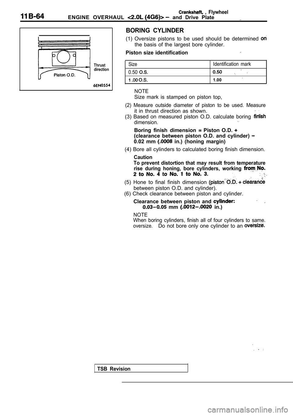
ENGINE OVERHAUL and Drive Plate
, Flywheel
Thrustdirection
BORING CYLINDER
(1) Oversize pistons to be used should be determine d
the basis of the largest bore cylinder.
Piston size identification
Size
0.50
1
NOTE
Identification mark
1.00
Size mark is stamped on piston top,
(2) Measure outside diameter of piston to be used. Measure
it in thrust direction as shown.
(3) Based on measured piston O.D. calculate boring
dimension.
Boring finish dimension Piston O.D.
(clearance between piston O.D. and cylinder)
0.02 mm in.) (honing margin)
(4) Bore all cylinders to calculated boring finish dimension.
Caution
To prevent distortion that may result from temperat ure
rise during honing, bore cylinders, working
(5) Hone to final finish dimension
between piston O.D. and cylinder).
(6) Check clearance between piston and cylinder.
Clearance between piston and
mm in.)
NOTE
When boring cylinders, finish all of four cylinders to same.
oversize.Do not bore only one cylinder to an
TSB Revision
Page 372 of 2103
ENGINE OVERHAUL Crankshaft, Flywheel ‘and ‘Drive Plate
Thrustdirection
B O R I N G C Y L I N D E R
(1) Oversize pistons to be used should determined on
the basis of the largest bore
Piston size identification
Size mark
0.50
1
NOTE
Size mark is stamped on piston top.
(2)
outside diameter of piston to be used.
it in thrust direction as shown.
(3) Based on measured piston O.D. calculate boring
Boring finish dimension
between piston O.D.
0.02 mm in.) (honing margin)
(4) Bore all cylinders to calculated boring finish dimension.
Caution
To prevent distortion that may result from temperat ure
rise during honing, bore cylinders, working from
2to No. 4 to No. 1 to No. 3.
(5) Hone to final finish dimension
clearance
between piston O.D. and cylinder).
(6) Check clearance between- piston and cylinder.
Clearance between piston and cylinder:
mm in.)
NOTE
When boring cylinders, finish all of four cylinders to same
Do not bore only one cylinder to an
TSB Revision
Page 1179 of 2103

AUTOMATIC TRANSAXLE
On-vehicle Service
TEST FOUR-SELECTOR IN
(1) Attach pressure to tap.,,;
(2) Move selector lever to the position,
(3) Allow vehicle wheels to turn and increase,
to achieve an indicated vehicle speed of
“mph).
(4) The clutch pressure should read 517 to
(75 to 95 psi).
(5) This test checks the clutch hydraulic circuit.
IN
(1) Attach pressure gauge to the torque
off pressure tap.
(2) Move selector lever to the position.’
(3) Allow vehicle wheels to turn and increase
to achieve an indicated vehicle speed of 80 km/h
m p h ) .
CAUTION
must turn at the ‘speed.
(4)
(5)Torque converter clutch off pressure should be
35 (5 psi).
This test checks the torque converter clutch
circuit.
. ,
TEST SIX-SELECTOR IN REVERSE
(1) Attach pressure gauge to the reverse clutch tap .
(2) Move selector lever to the reverse position.
(3) Read reverse clutch pressure with output statio nary (foot
on brake) and throttle opened to achieve 1,500
(4) Reverse clutch pressure should read 1,138 to 1, 620
(165 to 235 psi).
(5) This test checks the reverse clutch hydraulic c ircuit.
TEST RESULT INDICATIONS
(1) If proper line pressure is found in any one test, the pump
and pressure regulator are working properly.
(2) Low pressure in all positions indicates a defec tive pump,
a clogged filter, or a stuck pressure regulator valve.
(3) Clutch circuit leaks are indicated if pressures do not fall
within the specified pressure range.
(4) If the overdrive clutch pressure is greater tha n 35
(5 psi) in step (6) of Test Three, a worn reaction shaft
seal ring is indicated.
TSB Revision