Page 1886 of 2103
BODY Door
DOOR LOCK POWER RELAY 2 CONTINUITY CHECK
(1) Removal the quarter trim (L.H.).
(Refer to GROUP
Trims.)
Removal the rear seat
(Refer to GROUP
Rear seat.
(2) Check for continuity between u n d e r t h e
conditions described below.
Battery voltageITerminal No.
2 34 ’ 57 8
Powerisnotsupplied00
0 -0
Power is supplied
- 0
TSB Revision1
Page 1887 of 2103
Door
DOOR OPENING WEATHERSTRIP
REMOVAL AND INSTALLATION
Door window inner weatherstripremoval steps
l Door trim (Refer to l Delta sash (Refer to 1. Belt line molding
2. Door outer opening weatherstrip
3. Door window inner weatherstrip
Door inner opening weatherstrip
removal steps
4. Drip line 5. Door holder Scuff plate (Refer to Trims.)
6. Door inner opening weatherstrip
TSB Revision
Page 1888 of 2103
BODY Door
REMOVAL AND INSTALLATION
1 ’
Door inner opening weatherstripremoval steps
l Scuff plate (Refer to GROUP Trims.)1. Door inner front openingweatherstrip2. Door inner rear openingweatherstrip
TSB Revision
REMOVAL SERVICE POINT
DOOR OUTER OPENING WEATHERSTRIP
REMOVAL
Make a tool as shown in the illustration to the door
opening weatherstrip.
Page 1890 of 2103

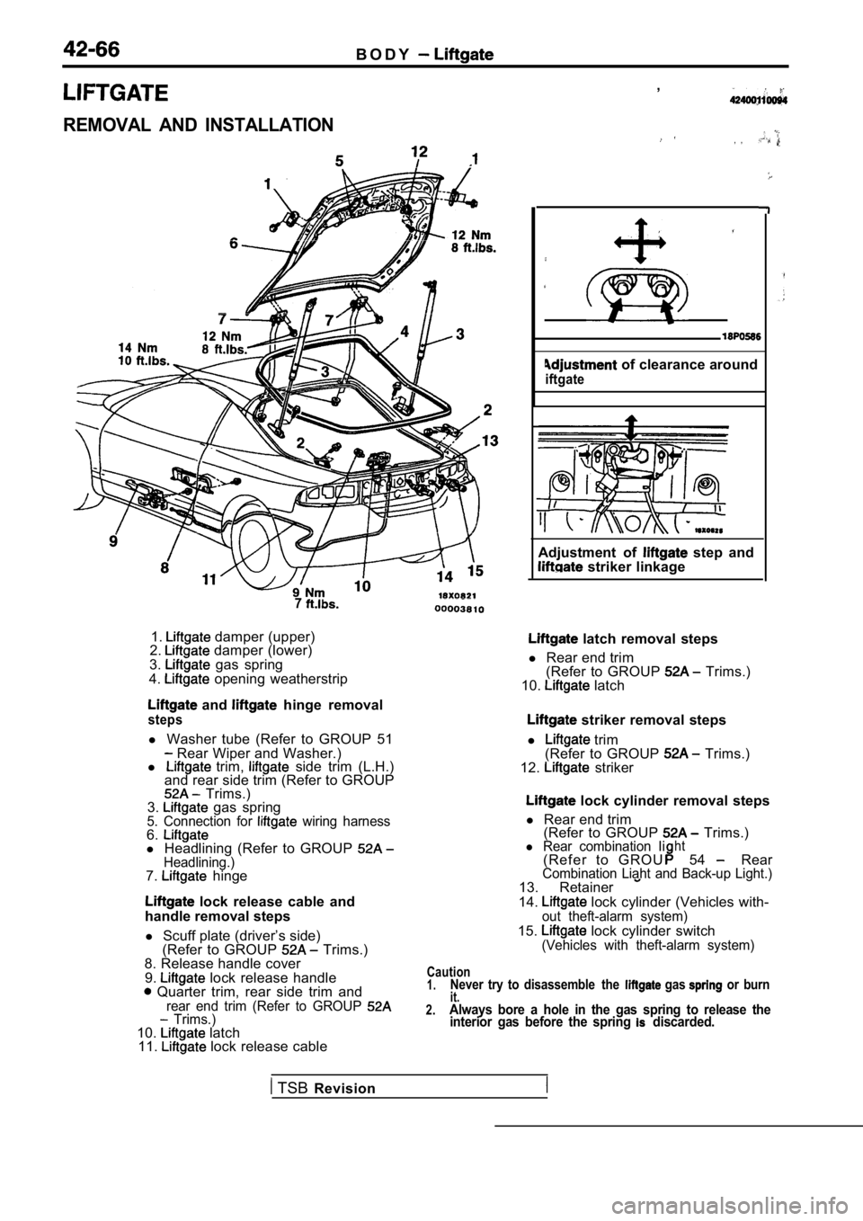
B O D Y
REMOVAL AND INSTALLATION
7
1. damper (upper)
2. damper (lower)
3. gas spring
4. opening weatherstrip
and hinge removal
steps
l Washer tube (Refer to GROUP 51 Rear Wiper and Washer.)
l trim, side trim (L.H.)
and rear side trim (Refer to GROUP
Trims.)
3. gas spring5. Connection for wiring harness6.l Headlining (Refer to GROUP Headlining.)7. hinge
lock release cable and
handle removal steps
l Scuff plate (driver’s side)
(Refer to GROUP
Trims.)
8. Release handle cover
9.
lock release handle Quarter trim, rear side trim andrear end trim (Refer to GROUP Trims.)10. latch
11. lock release cable ,
, ,
of clearance around
iftgate
Adjustment of step and striker linkage
latch removal steps
l Rear end trim
(Refer to GROUP
Trims.)
10. latch
striker removal steps
l
trim
(Refer to GROUP Trims.)
12. striker
lock cylinder removal steps
l Rear end trim
(Refer to GROUP
Trims.)l Rear combination Iiht( R e f e r t o G R O U54 RearCombination Liaht and Back-up Light.)13. Retainer
14. lock cylinder (Vehicles with-out theft-alarm system)
15. lock cylinder switch(Vehicles with theft-alarm system)
Caution1.Never try to disassemble the gas or burnit.2.Always bore a hole in the gas spring to release the interior gas before the spring discarded.
TSB Revision
Page 1893 of 2103
BODY Trunk Lid
TRUNK LID
REMOVAL AND INSTALLATION
of trunk lid step
trunk lid striker linkageAdjustment of clearance
around trunk lid
1. Bumper
2. Trunk lid striker
3. Trunk lid opening weatherstrip
Trunk lid latch removal steps
l Rear end trim (Refer to GROUP
Trims.)4. Trunk lid latch
Caution1.Never try to disassemble the gas spring
or burn it.
2.Always bore a hole in the gas spring to release
the interior gas before the spring is discarded.
0 0 0 0 4 7 5 2
Trunk lid gas spring removal steps 6. Lock cover
7. Trunk lid gas spring
8. Ball joint
Trunk lid removal steps
5. Harness connector
6. Lock cover
7. Trunk lid gas spring
9. Trunk lid hinge
10. Trunk lid
TSB Revision
Page 1895 of 2103
BODY Trunk Lid Lock Release Handle and Cable
REMOVAL AND INSTALLATION
Trunk lid lock release handleremoval steps
1. Release handle cover2. Retainer3. Lock cylinder
l Scuff plate (Driver’s side)
(Refer to GROUP
Trims.)
l Front seat (Driver’s side)
(Refer to GROUP
Front seat.)
4. Trunk lid lock release handle
. .
Adjustment of trunk lid step
frunk lid striker linkage .
Trunk lid lock cableremoval steps
1. Release handle cover
l Scuff plate (Driver’s side)
(Refer to GROUP
Trims.)
l Front seat (Driver’s side)
(Refer to GROUP
Front seat.)
4. Trunk lid lock release handlel Quarter trim, lower (L.H.) and luggagecompartment side trim (Refer to GROUP 5. Trunk lid latch
6. Trunk lid lock release cable
TSB Revision
Page 1901 of 2103
B O D Y Entry System
ENTRY SYSTEM
R E M O V A L A N D
Pre-removal and Post-installation Operation
l Quarter trim (L.H.) (Refer to GROUP Trims.)
Removal steps
1. Door lock power relay 2
2. Receiver assembly
TSB Revision
Page 1918 of 2103
BODY Electric Convertible Top
CONVERTIBLE TOP FIT ADJUSTMENT
(1) Remove the quarter trim, lower (Refer to GROUP
Trims.)
(2) Fully open orclose the top, then adjust the stopper
adjusting bolt so it contacts the flange as shown in the
illustration.
CONVERTIBLE TOP ASSEMBLY
REMOVAL AND INSTALLATION
Pre-removal OperationCompletely open the convertible top.Post-installation OperationConvertible top fit adjustment
8
View A
18
View A
76 7
5
Removal steps
3. Strip
l
Quarter belt moulding
(Refer to GROUP 51
Mouldings.) Quarter trim, lower
(Refer to GROUP Trims.)l Rear speaker(Refer to GROUP 54 Speaker.)
1. drive motor connector
2. Clip
4. Side attaching hook5. Defogger connectorl (Refer to GROUP
6. Rear strap
7. Drain trough rear attaching clip
8. Convertible top assembly
TSBRevision