1990 MITSUBISHI SPYDER diagram
[x] Cancel search: diagramPage 291 of 2103
ENGINECamshaft
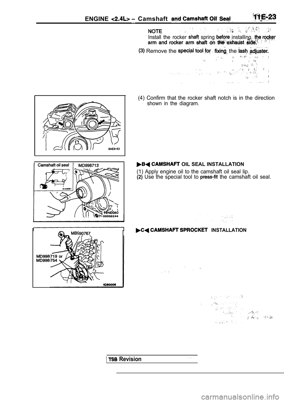
Install the rocker spring installing,
Remove the the
.
.,
(4) Confirm that the rocker shaft notch is in the direction
shown in the diagram.
OIL SEAL INSTALLATION
(1) Apply engine oil to the camshaft oil seal lip.
(2)Use the special tool to the camshaft oil seal.
INSTALLATION
Revision
Page 522 of 2103
E N G I N E ( T U R B O )
AND
ENGINE> General . .
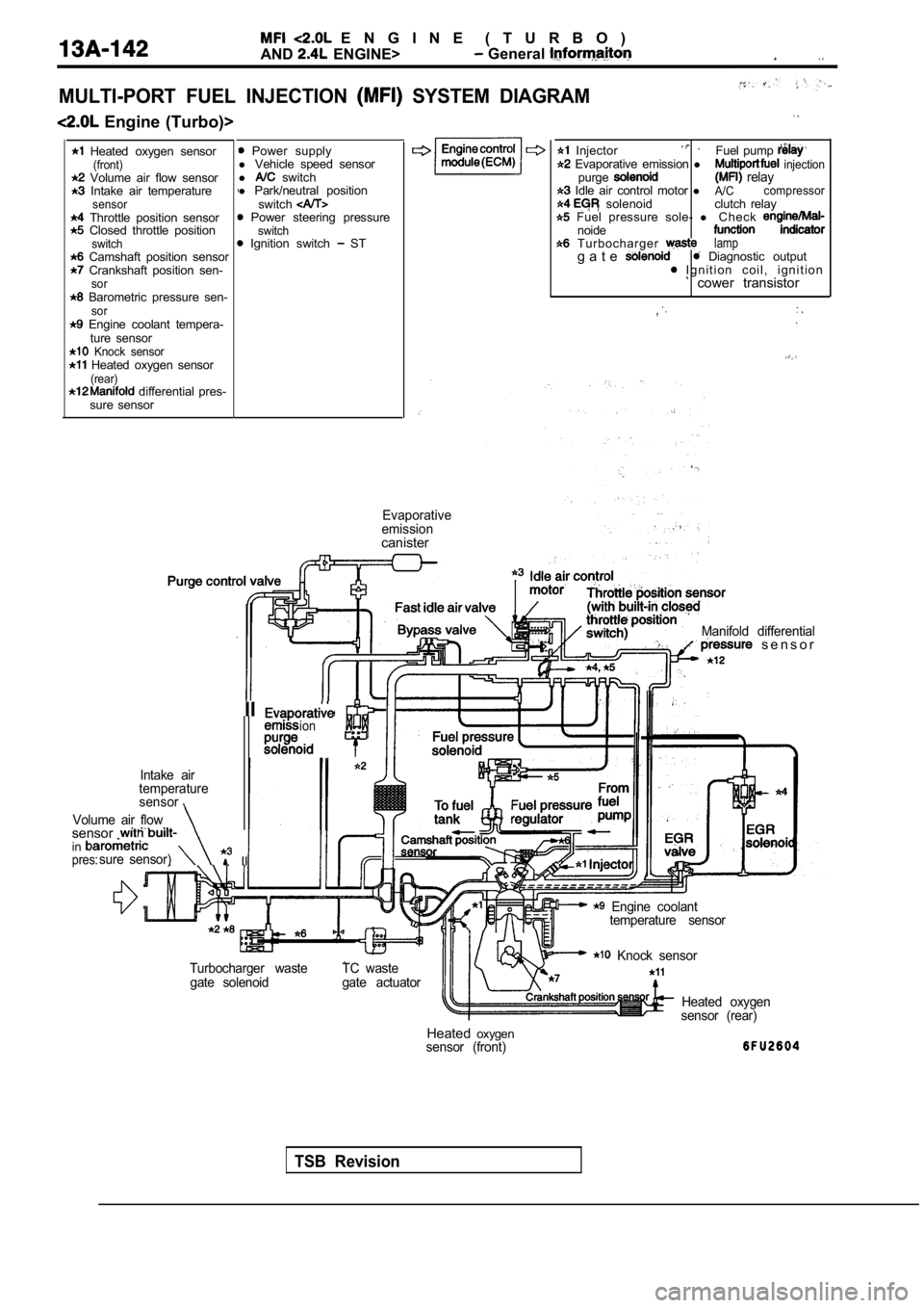
MULTI-PORT FUEL INJECTION SYSTEM DIAGRAM
Engine (Turbo)>
Heated oxygen sensor(front) Volume air flow sensor Intake air temperaturesensor Throttle position sensor Closed throttle positionswitch Camshaft position sensor Crankshaft position sen-sor Barometric pressure sen-sor Engine coolant tempera- ture sensor
Knock sensor Heated oxygen sensor(rear) differential pres-
sure sensor
Power supply
l Vehicle speed sensor
l
switch
l Park/neutral position
switch
Power steering pressureswitch Ignition switch ST
Enginecontrol Injector . Fuel pump
Evaporative emission l injectionpurge relay Idle air control motor lA/Ccompressor solenoid clutch relay Fuel pressure sole-
l C h e c knoide T u r b o c h a r g e r lampg a t e Diagnostic output I g n i t i o n c o i l , i g n i t i o n cower transistor
,
Evaporative
emission
canister
TSB Revision
Manifold differential s e n s o r
IIion. .
Intake air
temperature
sensor
Volume air flow
sensor . insure sensor) IIpres:
Engine coolant temperature sensor
Turbocharger waste gate solenoid TC waste
gate actuator
Knock sensor
Heated oxygen
sensor (rear)
Heated oxygensensor (front)
Page 673 of 2103
1.4
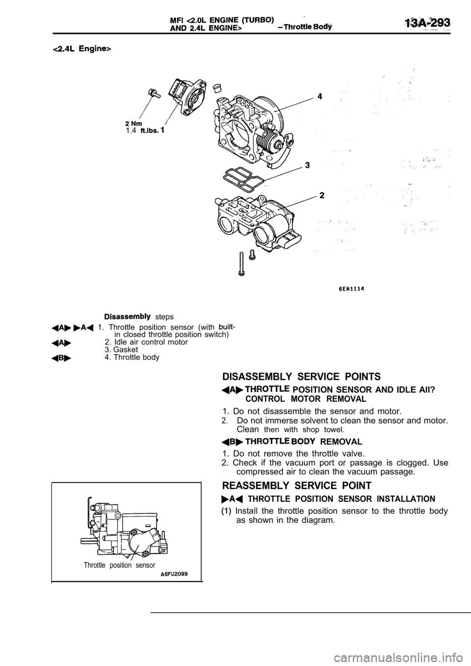
steps
1. Throttle position sensor (with in closed throttle position switch)2. Idle air control motor
3. Gasket
4. Throttle body
DISASSEMBLY SERVICE POINTS
POSITION SENSOR AND IDLE All?
CONTROL MOTOR REMOVAL
1. Do not disassemble the sensor and motor.
2.Do not immerse solvent to clean the sensor and moto r.
Clean then with shop towel.
REMOVAL
1. Do not remove the throttle valve.
2. Check if the vacuum port or passage is clogged. Use
compressed air to clean the vacuum passage.
REASSEMBLY SERVICE POINT
THROTTLE POSITION SENSOR INSTALLATION
Install the throttle position sensor to the thrott le body
as shown in the diagram.
Throttle position sensor
Page 692 of 2103
14-2ENGINE COOLING General Information
GENERAL INFORMATION , ,
The cooling system is designed to keep every partthat the heat absorbed by the coolant may be of the engine at appropriate temperature in diated into the air.
er condition the engine may be operated.
The cooling of the water-cooled, pressureThe water pump is of the centrifugal type and is
driven by the
the
forced circulation type in which the water pump crankshaft. .
pressurizes coolant and circulates it throughout th e
engine: If the coolant temperature exceeds the
scribed temperature, the thermostat opens to circu-
late the coolant through the radiator as well so
and is cooled the
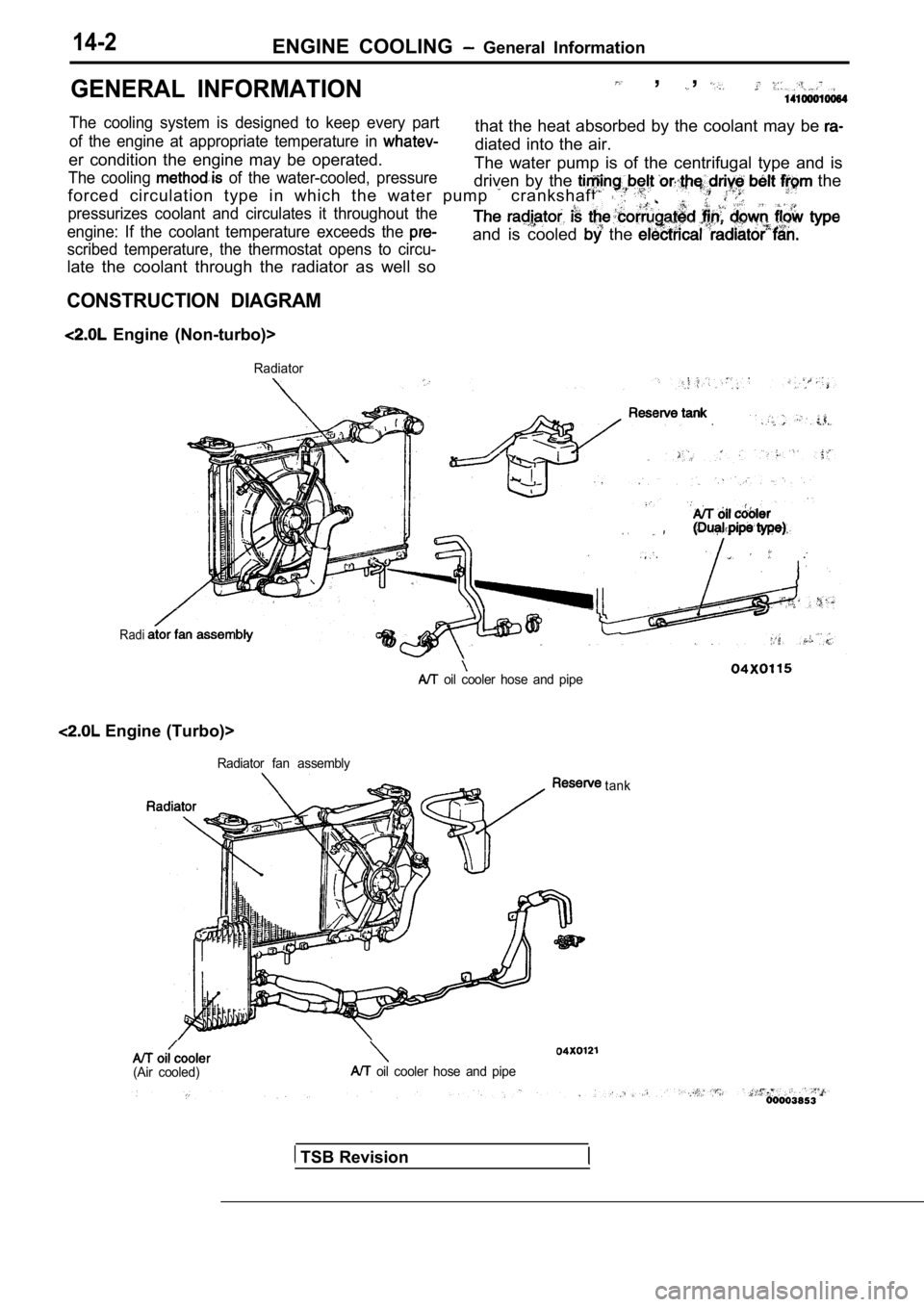
CONSTRUCTION DIAGRAM
Engine (Non-turbo)>
Radiator
Radi
.
oil cooler hose and pipe
Engine (Turbo)>
Radiator fan assembly
(Air cooled) oil cooler hose and pipetank
TSB Revision
Page 742 of 2103
17-2
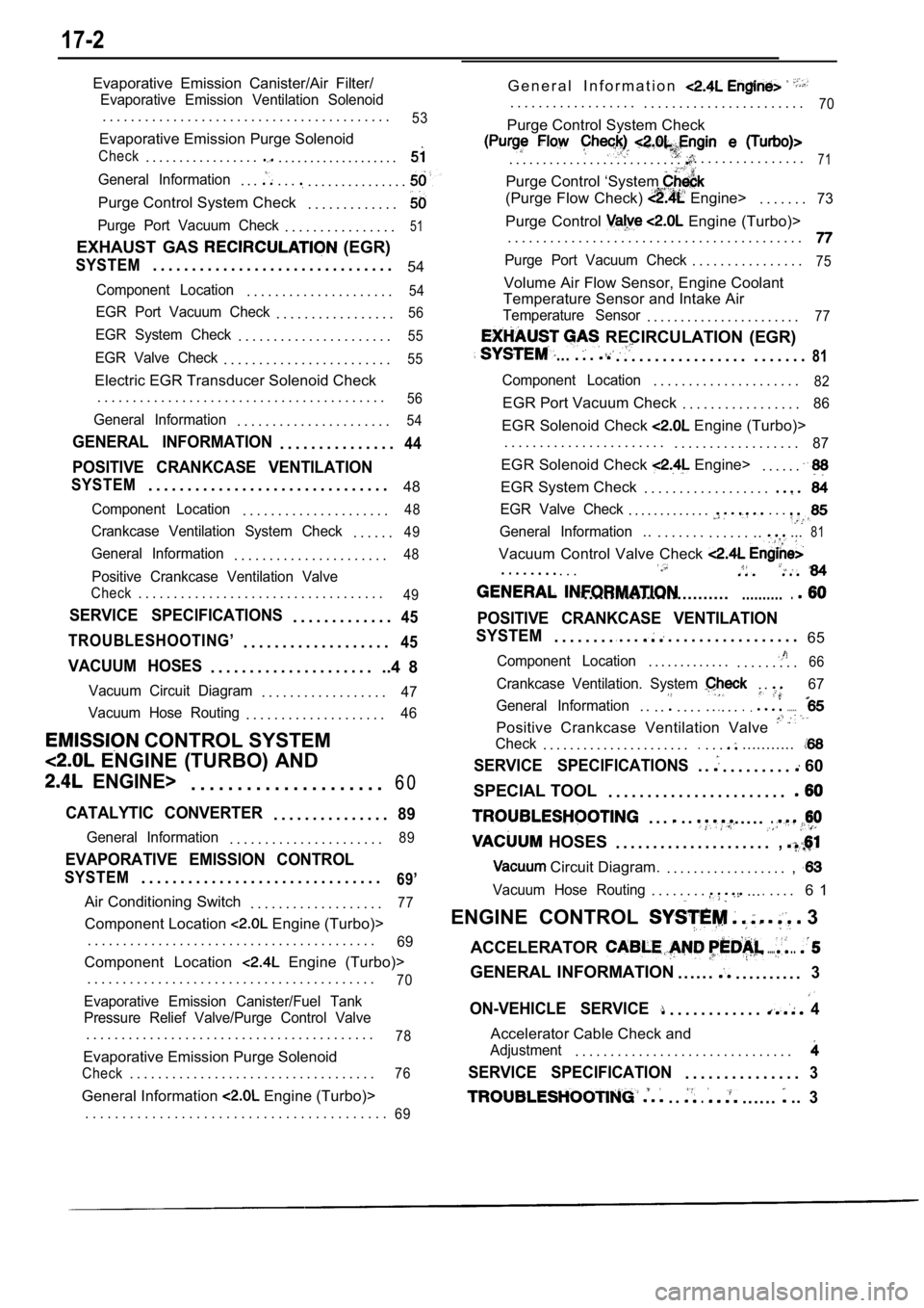
Evaporative Emission Canister/Air Filter/
Evaporative Emission Ventilation Solenoid
. . . . . . . . . . . . . . . . . . . . . . . . . . . . . . . . . . . . . . . . .53
Evaporative Emission Purge Solenoid
Check. . . . . . . . . . . . . . . . .. . . . . . . . . . . . . . . . . . .
General Information. . .. . .. . . . . . . . . . . . . . .
Purge Control System Check. . . . . . . . . . . . .
Purge Port Vacuum Check. . . . . . . . . . . . . . . .51
EXHAUST GAS (EGR)
SYSTEM. . . . . . . . . . . . . . . . . . . . . . . . . . . . . . . 54
Component Location. . . . . . . . . . . . . . . . . . . . .54
EGR Port Vacuum Check. . . . . . . . . . . . . . . . .56
EGR System Check. . . . . . . . . . . . . . . . . . . . . .55
EGR Valve Check. . . . . . . . . . . . . . . . . . . . . . . .55
Electric EGR Transducer Solenoid Check
. . . . . . . . . . . . . . . . . . . . . . . . . . . . . . . . . . . . . . . . .
56
General Information. . . . . . . . . . . . . . . . . . . . . .54
GENERAL INFORMATION. . . . . . . . . . . . . . .44
POSITIVE CRANKCASE VENTILATION
SYSTEM. . . . . . . . . . . . . . . . . . . . . . . . . . . . . . . 48
Component Location. . . . . . . . . . . . . . . . . . . . .48
Crankcase Ventilation System Check. . . . . .49
General Information. . . . . . . . . . . . . . . . . . . . . .48
Positive Crankcase Ventilation Valve
Check. . . . . . . . . . . . . . . . . . . . . . . . . . . . . . . . . . .49
SERVICE SPECIFICATIONS. . . . . . . . . . . . .45
TROUBLESHOOTING’
. . . . . . . . . . . . . . . . . . .45
VACUUM HOSES. . . . . . . . . . . . . . . . . . . . . ..4 8
Vacuum Circuit Diagram. . . . . . . . . . . . . . . . . .47
Vacuum Hose Routing
. . . . . . . . . . . . . . . . . . . .46
CONTROL SYSTEM
ENGINE (TURBO) AND
ENGINE>. . . . . . . . . . . . . . . . . . . . . 6 0
CATALYTIC CONVERTER. . . . . . . . . . . . . . .89
General Information. . . . . . . . . . . . . . . . . . . . . .89
EVAPORATIVE EMISSION CONTROL
SYSTEM. . . . . . . . . . . . . . . . . . . . . . . . . . . . . . .69’
Air Conditioning Switch
. . . . . . . . . . . . . . . . . . .77
Component Location Engine (Turbo)>
. . . . . . . . . . . . . . . . . . . . . . . . . . . . . . . . . . . . . . . . .
69
Component Location Engine (Turbo)>
. . . . . . . . . . . . . . . . . . . . . . . . . . . . . . . . . . . . . . . . .
70
Evaporative Emission Canister/Fuel Tank
Pressure Relief Valve/Purge Control Valve
. . . . . . . . . . . . . . . . . . . . . . . . . . . . . . . . . . . . . . . . .78
Evaporative Emission Purge Solenoid
Check. . . . . . . . . . . . . . . . . . . . . . . . . . . . . . . . . . .76
General Information Engine (Turbo)> G e n e r a l I n f o r m a t i o n
. . . . . . . . . . . . . . . . . .
. . . . . . . . . . . . . . . . . . . . . . .70
Purge Control System Check
. . . . . . . . . . . . . . . . . . . . . . . . . .. . . . . . . . . . . . . . . .71
Purge Control ‘System
(Purge Flow Check) Engine>. . . . . . .73
Purge Control Engine (Turbo)>
. . . . . . . . . . . . . . . . . . . . . . . . . . . . . . . . . . . . . . . . . .
Purge Port Vacuum Check. . . . . . . . . . . . . . . .75
Volume Air Flow Sensor, Engine Coolant
Temperature Sensor and Intake Air
Temperature Sensor. . . . . . . . . . . . . . . . . . . . . . .77
RECIRCULATION (EGR)
.... . .. . . . . . . . . . . . . . . . . . . . . . . .81
Component Location. . . . . . . . . . . . . . . . . . . . .82
EGR Port Vacuum Check . . . . . . . . . . . . . . . . .86
EGR Solenoid Check Engine (Turbo)>
. . . . . . . . . . . . . . . . . . . . . . . . . . . . . . . . . . . . . . . . .
87
EGR Solenoid Check Engine>. . . . . .
EGR System Check . . . . . . . . . . . . . . . . . .
EGR Valve Check. . . . . . . . . . . . .. . .
General Information... . . . . . . . . . . . . .....81
Vacuum Control Valve Check
. . . . . . . . .
.......................................
POSITIVE CRANKCASE VENTILATION
SYSTEM
. . . . . . . ... . .. . . . . . . . . . . . . . . . . 65
Component Location. . . . . . . . . . . . .. . . . . . . . .66
Crankcase Ventilation. System . .67
General Information
. . . .. . . . . ... . ........
Positive Crankcase Ventilation Valve
Check. . . . . . . . . . . . . . . . . . . . . ... . ............
SERVICE SPECIFICATIONS. .. . . . . . . . . 60
SPECIAL TOOL . . . . . . . . . . . . . . . . . . . . . . .
. . .. .
HOSES
. . . . ..
. . . . . . . . . . . . . . . . . . . . .,
Circuit Diagram.. . . . . . . . . . . . . . . . . . ,
Vacuum Hose Routing. . . . . . . ...... . . . 6 1
ENGINE CONTROL
3
ACCELERATOR
......
GENERAL INFORMATION . . . . . .. . . . . . . . . .3
ON-VEHICLE SERVICE. . . . . . . . . . . .4
Accelerator Cable Check and
Adjustment. . . . . . . . . . . . . . . . . . . . . . . . . . . . . . .
SERVICE SPECIFICATION. . . . . . . . . . . . . . .3
. ... . . . . ...3. . . . . . . . . . . . . . . . . . . . . . . . . . . . . . . . . . . . . . . . .
69
Page 787 of 2103
Emission
ENGINE AND EMISSION
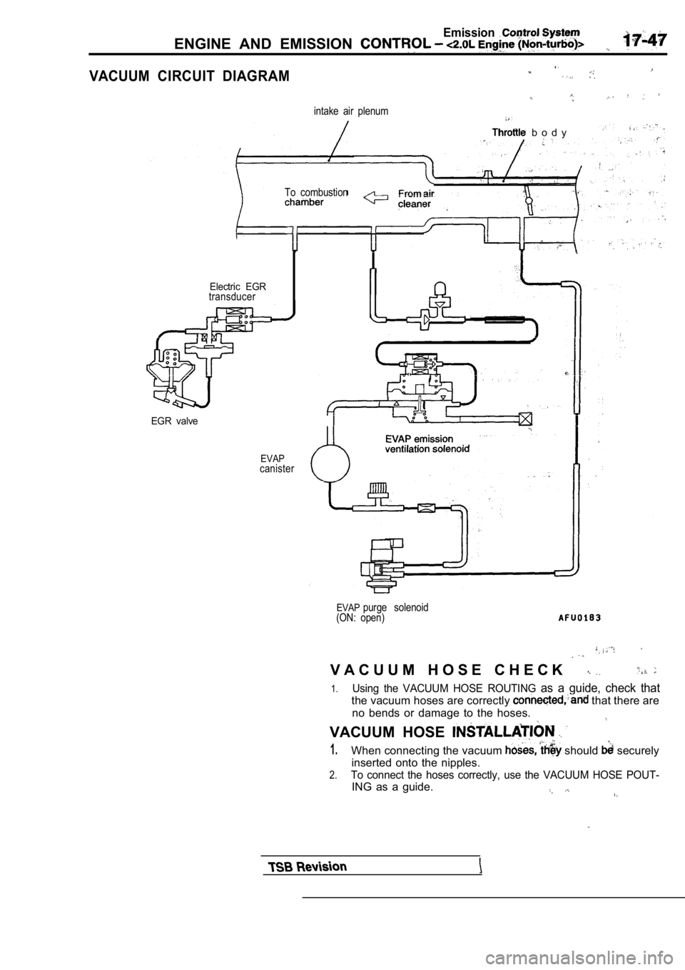
VACUUM CIRCUIT
.
DIAGRAM
intake air plenum
b o d y
To combustion
Electric EGRtransducer
EGR valve
EVAPcanister
EVAPpurge solenoid
(ON: open)
V A C U U M H O S E C H E C K
1.Using the VACUUM HOSE ROUTING as a guide, check that
the vacuum hoses are correctly that there are
no bends or damage to the hoses.
VACUUM HOSE
1.When connecting the vacuum should securely
inserted onto the nipples.
2.To connect the hoses correctly, use the VACUUM HOSE POUT-
ING as a guide.
Page 788 of 2103
Emission Control System
ENGINE AND EMISSION CONTROL Engine
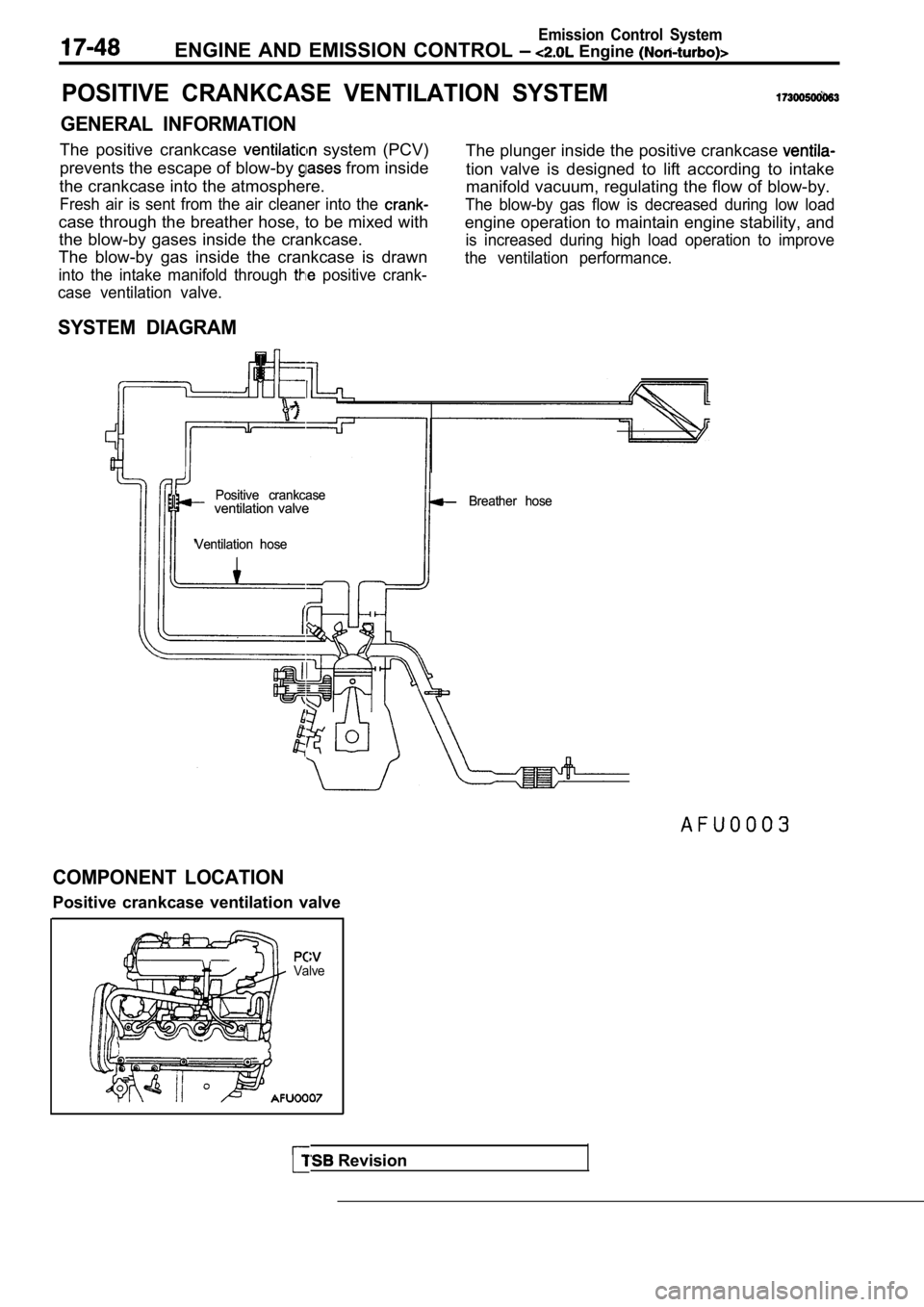
POSITIVE CRANKCASE VENTILATION SYSTEM
GENERAL INFORMATION
The positive crankcase system (PCV)
prevents the escape of blow-by
from inside
the crankcase into the atmosphere.
Fresh air is sent from the air cleaner into the
case through the breather hose, to be mixed with the blow-by gases inside the crankcase.
The blow-by gas inside the crankcase is drawn
into the intake manifold through positive crank-
case ventilation valve.
The plunger inside the positive crankcase
tion valve is designed to lift according to intake
manifold vacuum, regulating the flow of blow-by.
The blow-by gas flow is decreased during low load
engine operation to maintain engine stability, and
is increased during high load operation to improve
the ventilation performance.
SYSTEM DIAGRAM
Positive crankcase
Positive crankcaseventilation valve
ventilation valve
Ventilation hose
Ventilation hose Breather hose
Breather hose
COMPONENT LOCATION
Positive crankcase ventilation valve
Valve
Revision
Page 802 of 2103
Engine and
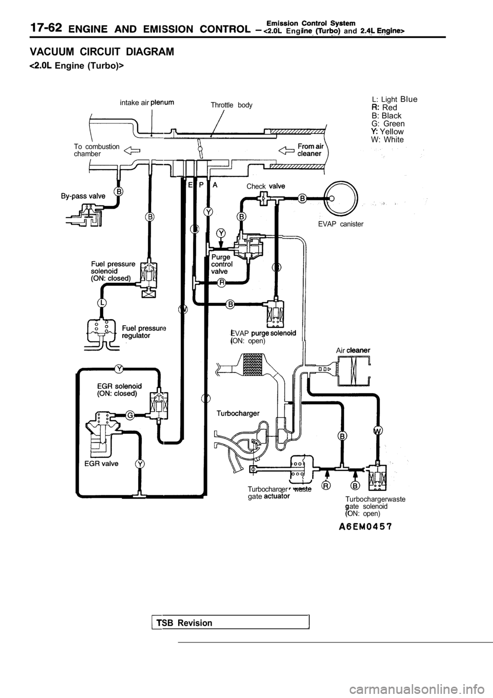
VACUUM CIRCUIT DIAGRAM
Engine (Turbo)>intake air
Throttle bodyL: Light Blue
Red
B: Black
G: Green YellowW: WhiteTo combustion
chamber
Check
EVAP(ON: open)
EVAP canister
TSB Revision
Air
Turbocharger wastegateTurbochargerwasteate solenoid
ON: open)