1990 MITSUBISHI SPYDER diagram
[x] Cancel search: diagramPage 1753 of 2103
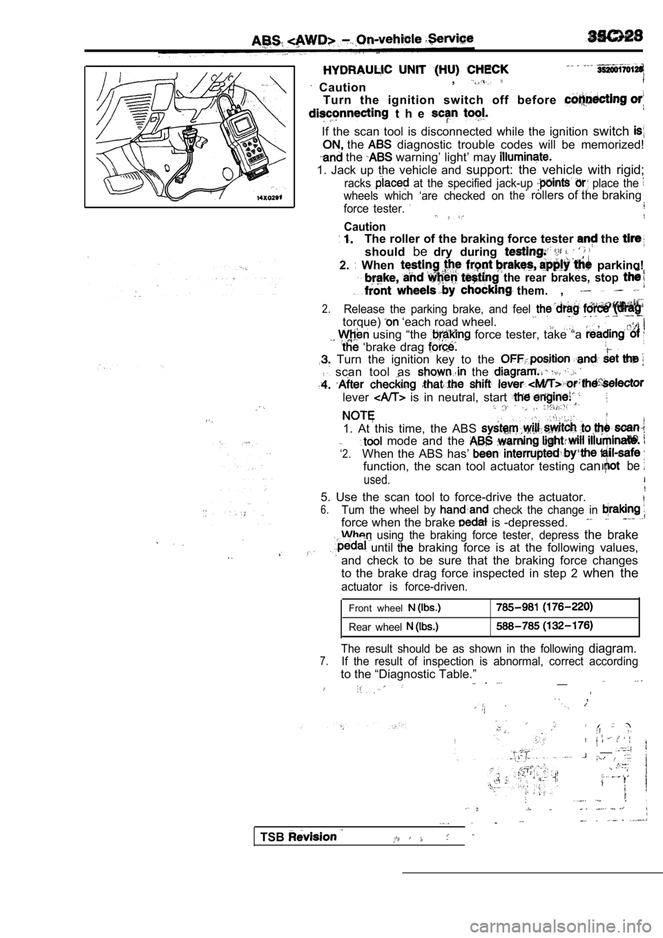
Caution,
Turn the ignition switch off before
t h e
If the scan tool is disconnected while the ignition
switch
the diagnostic trouble codes will be memorized!
the warning’ light’ may
1. Jack up the vehicle and support: the vehicle with rigid;
racks at the specified jack-up place the
wheels which ‘are checked on. .therollers of the braking
force tester.
Caution
The roller of the braking force tester the
shouldbedry during
2. When parking!
the rear brakes, stop
them.,
2.Release the parking brake, and feel
torque) ‘each road wheel. .
using “the force tester, take “a
‘brake drag
Turn the ignition key to the
scan tool as the
lever is in neutral, start
1. At this time, the ABS
‘2.
mode and the
When the ABS has’
function, the scan tool actuator testing canbe
used.
5. Use the scan tool to force-drive the actuator.
6.Turn the wheel by check the change in
force when the brake is -depressed.
using the braking force tester, depress the brake
until braking force is at the following values,
and check to be sure that the braking force changes
to the brake drag force inspected in step 2 when the
actuator is force-driven.
Front wheel
Rear wheel
The result should be as shown in the following diagram.
7.If the result of inspection is abnormal, correct ac cording
to the “Diagnostic Table.”__ .
,
__
TSB
Page 1776 of 2103
STEERING General Information
G E N E R A L I N F O R M A T I O N
The type of power steering which is responsive
to engine speed has been adopted in all models.
The main features are as follows. The steering column in all vehicles has a shock
absorber mechanism and a tilt steering mechanism.
Four-spoke steering wheel has been adopted. In
A vane-type oil pump a fluid flow control system
addition, (Supplemental Restraint System) is
included adopted.
provided as a standard in all
The gear linkage is an integral rack
and
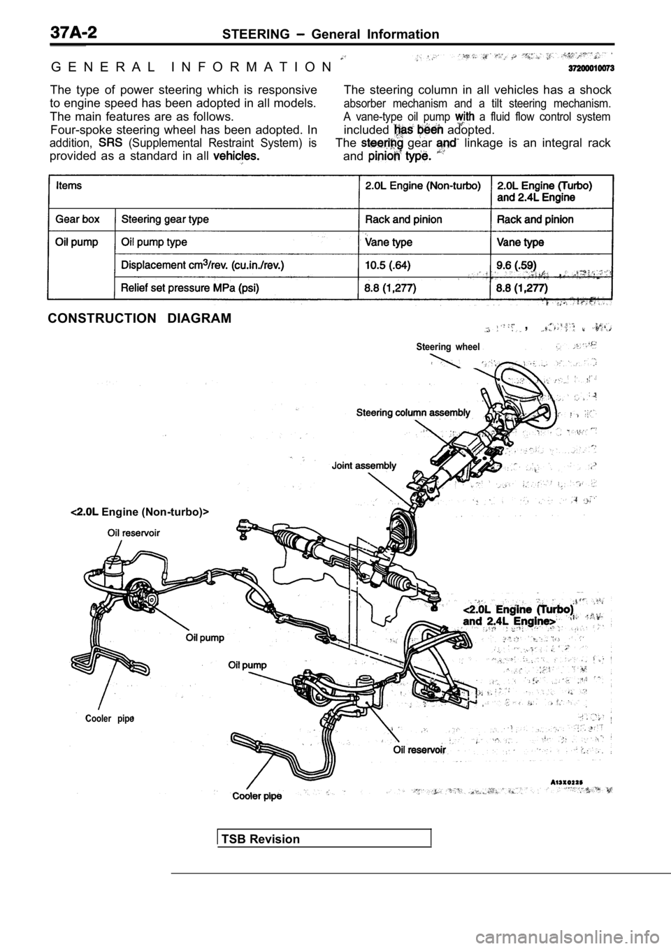
CONSTRUCTION DIAGRAM,
Steering wheel
Cooler pipe
Engine (Non-turbo)>
TSB Revision
Page 1997 of 2103
SUPPLEMENTAL,
SYSTEM
CONTENTS
AIR BAG MODULES DISPOSAL
PROCEDURES. . . . . . . . . . . . . . . . . . . . . . . . . . . .40
Deployed Air Bag Module Disposal . . . . . . . . . . .
44
Undeployed Air Bag Module Disposal . . . . . . . .40
AIR BAG MODULES AND CLOCK
SPRING. . . . . . . . . . . . . . . . . . . . . . . . . . . . . . . . .34
COMPONENT SERVICE
. . . . . . . . . . . . . . . . . . .31
GENERAL INFORMATION. . . . . . . . . . . . . . . . . .2
Circuit Diagram. . . . . . . . . . . . . . . . . . . . . . . . . . . . . .8
Componeni Location. . . . . . . . . . . . . . . . . . . . . . . .10
Configuration Diagrams. . . . . . . . . . . . . . . . . . . . . . .7
Construction Diagram. . . . . . . . . . . . . . . . . . . . . . . .3
Introduction. . . . . . . . . . . . . . . . . . . . . . . . . . . . . . . . . .2
Schematic. . . . . . . . . . . . . . . . . . . . . . . . . . . . . . . . . . .8
Warning/Caution Labels. . . . . . . . . . . . . . . . . . . . . . 4
MAINTENANCE. . . . . . . . . . . . . . . . . . . . . . . . . . .28
POST-COLLISION DIAGNOSIS
. . . . . . . . . . . .28
SPECIAL TOOLS. . . . . . . . . . . . . . . . . . . . . . . . . .13
SERVICE PRECAUTIONS. . . . . . . . . . . . . . . . . .11
SERVICE SPECIFICATIONS. . . . . . . . . .. . . .12
SRS AIR BAG UNIT (SRS-ECU)
. . . . . . . . . . . . . . . . . . . . . . . . . . . . . . . . . . . . . . . . . . .
32
TEST EQUIPMENT. . . . . . . . . . . . . . . . . . . . . . . .13
TROUBLESHOOTING. . . . . . . . . . . . . . . . . . . . .14
CAUTION
lCarefully read and observe the information in the S ERVICE PRECAUTIONS Prior to any service.lFor information troubleshooting or maintenance, always observe the procedures in the Troubleshooting or the respectively.
lIf any SRS components are removed or replaced in co nnection with any service procedures, be sure to follow the dures the COMPONENT SERVICE section for the components involved.lIf you have any questions about the please contact the Tech. Line.
Page 1999 of 2103
SRS General
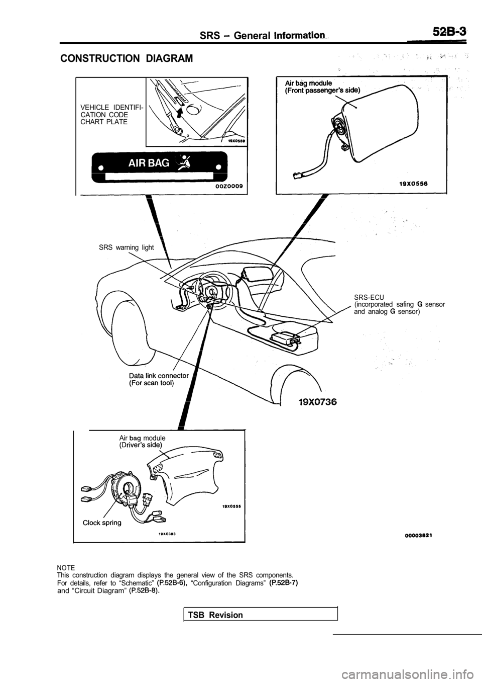
CONSTRUCTION DIAGRAM
VEHICLE IDENTIFI-CATION CODE
CHART PLATE
Air
module
SRS warning light
SRS-ECU(incorporated safing sensor
and analog sensor)
NOTEThis construction diagram displays the general view of the SRS components.
For details, refer to “Schematic” “Configuration Diagrams” and “Circuit Diagram”
TSB Revision
Page 2003 of 2103
SRS General Information
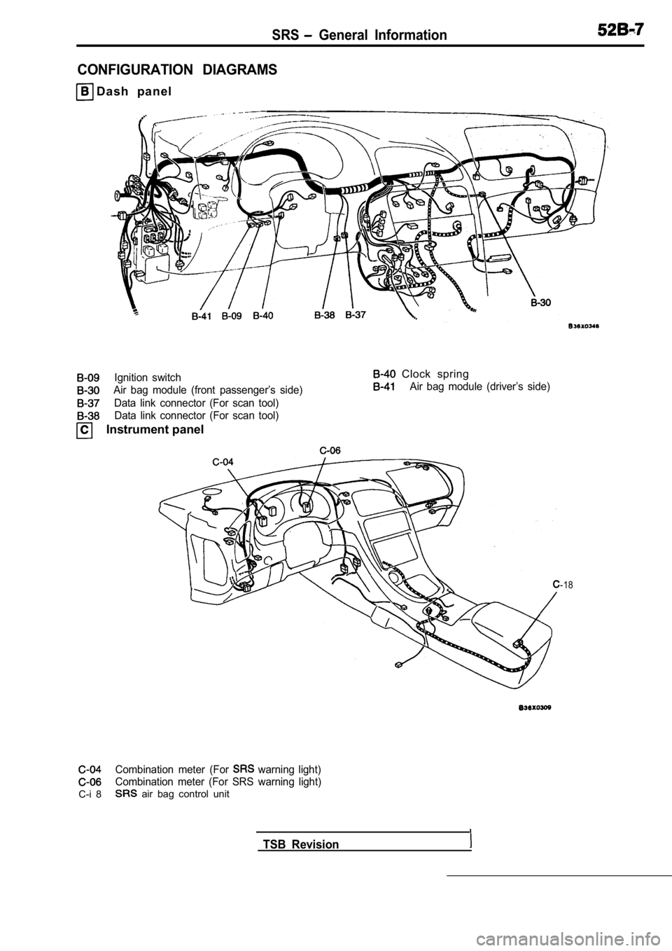
CONFIGURATION DIAGRAMS
D a s h p a n e l
Ignition switch
Air bag module (front passenger’s side)
Data link connector (For scan tool)Data link connector (For scan tool)
Instrument panel
Clock spring
Air bag module (driver’s side)
-18
Combination meter (For warning light)
Combination meter (For SRS warning light)
C-i 8 air bag control unit
TSB Revision
Page 2004 of 2103
SRS General Information.
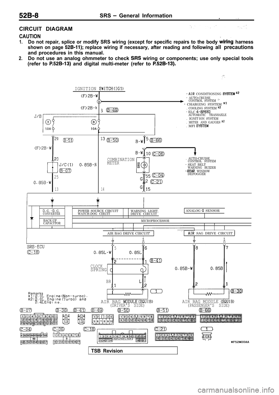
CIRCUIT DIAGRAM
CAUTION
1.Do not repair, splice or modify SRS wiring (except for specific repairs to the body harness
shown on page
replace wiring if necessary, after reading and fol lowing all precautions
and procedures in this manual.
2.Do not use an analog ohmmeter to check wiring or components; use only special tools
(refer to
and digital multi-meter (refer to
IGNITION
23
I
25
13
CONDITIONING AUTO-CRUISECONTROL SYSTEM CHARGING SYSTEM . COOLING SYSTEM
. IGNIT. METER. MFI
ELC AUTOMATIC TRANSAXLE ION SYSTEMAND GAUGES
14
COMBINATIONMETER
. AUTO-CRUISECONTROL SYSTEM SEAT BELTWARNING BUZZER WINDOWDEFOGGER
C. C.POWER SOURCE CIRCUITCONVERTERWATCH-DOG CIRUIT WARNING LIGHT,
DRIVE CIRCUIT ANALOG SENSOR
I IIIBACK-UP
CAPACITORMICROPROCESSORI
AIR BAG DRIVE CIRCUIT
SAG DRIVE CIRCUIT IIIAA
5 6 8
7
2CLOCKSPRINGI
BR2 21
R e m a r k s
n e .AIR BAG AIR BAG MODULE (DRIVER'S SIDE) (PASSENGER'S SIDE)
TSB Revision
Page 2094 of 2103
2ALPHABETICAL INDEX
BY PASS VALVE, Check . . . . . . . . . . . . . . . , . . .
CABLEAccelerator
. . . . . . . . . . . . . . . . . . . . . . . . . . . . . . . . . . . . . . . . .Accelerator, Check and Adjustment. . . . . . . . . . . . . . . . . . . .Auto-cruise Control, Check and Adjustment. . . . . . . . . . . .Ignition, Maintenance. . . . . . . . . . . . . . . . . . . . . . . . . . . . . . Brake . . . . . . . . . . . . . . . . . . . . . . . .. . . . . . . . . . . . . . . . .Spark Resistance Check EN8 (NON-TURBO)>. . . . . . . . . . . . . . . . . . . . .Spark Resistance Check EN8 (TURBO) AND ENGINE>.. . . . . . . .Spark , Test ENGINE (TURBO) AND. . . . . . . . . . . . . . . . . . . . . . . . . . . . . . . . . . . .CAM FOLLOWER . . . . . . . . . . . . . . . . . . . . . .11CAMSHAFT
. . . . . . . . . . . . . . . . . . . . . . . . . . .. . . . . . . . . . . . . . . . . . . . . . . . . . . . .. . . . . . . . . . . . . . . . . . . . . . . . . . . . . . . . . .CAMSHAFT OIL SEALS
. . . . . . . . . . . . . . . . . . . . . . . . . . . . . . . . . . .
. . . . . . . . . . . . . . . . . . . . . . . . . . . . . . . . . . . . .. . . . . . . . . . . . . . . . . . . . . . . . . . . . . . . . . . . . . . . . . . .
CAMSHAFT POSITION SENSOR
ENGINE (NON-TURBO)>. . . . . . . . . . . . . . . . . . . . . ENGINE (TURBO)>. . . . . . . . . . . . . . . . . . . . . . . . . . ENGINE>. . . . . . . . . . . . . . . . . . . . . . . . . . . . . . . . . . .CANISTER
Evaporative Emission
ENGINE (NON-TURBO)> . . . . . . . . . . . . . . . . . . . E N G I NE (TUR B O )A N D E N G I N E >
. . . . . . .CAP VALVE, Opening Pressure Test. . . . . . . . . . . . . . . . . . . . . .CARRIER, Differential . . . . . . . . . . . . . . . . . . . . . . . . . .CASE, Front
. . . . . . . . . . . . . . . . . . . . . . . . . . . . . . . . . . .. . . . . . . . . . . . . . . . . . . . . . . . . . . . . . . . . . . . . . . . . . .11CASE
LSD. . . . . . . . . . . . . . . . . . . . . . . . . . . . . . . . . . . . . . .
Transfer. . . . . . . . . . . . . . . . . . . . . . . . . . . . . .CATALYTIC CONVERTER ENGINE (NON-TURBO)>. . . . . . . . . . . . . . . . . . . . . . ENGINE (TURBO) AND ENGINE>.. . . . . . . . .CD PLAYER. . . .
. . . . . . . . . . . . . . . . . . . . . . . . . . . . . . . . . . . . .CENTER DIFFERENTIAL
. . . . . . . . . . . . . . . . . . . . . . . . . . . . . . . . . . . . . .
. . . . . . . . . . . . . . . . . . . . . . . . . . . . . . . . . . . . . .C E N T E R M E M B E R. . . . . . . . . . . . . . . . . . . . . . . . . . . . . . . . . . . . .CHARGE AIR COOLER. . . . . . . . . . . . . . . . . . . . . . . . . . . . . . . . .CHARGING . . . . . . . . . . . . . . . . . . . . . . . . . . . . . . . . . . . . . . CHARGING SYSTEM ENGINE (NON-TURBO)>. . . . . . . . . . . . . . . . . . . . . . ENGINE (TURBO) AND ENGINE>.. . . . . . . .CHECK VALVE, Operation Check. . . . . . . . . . . . . . . . . . . . I
CIGARETTE LIGHTER. . . . . . . . . . . . . . . . . . . . . . . . . . . . . . .54-61CIRCUIT DIAGRAM. . . . . . . . . . . . . . . . . . . . . . . . . . . . . . . . . .CLOCK SPRING .. . . . . . . . . . . . . . . . . . . . . . . . . . . . . . . . . . .CLOSED POSITION SWITCH ENGINE (TURBO) AND Adjustment. . . . . . . . . . . . . . . . . . . . . . . . . . . . . . . . . . . . .On-vehicle Inspection. . . . . . . . . . . . . . . . . . . . . . . . . . . .CLUTCH . . . . . . . . . . . . . . . . . . . . . . . . . . . . . . . . . . . . . . . . . . . .21End. . . . . . . . . . . . . . . . . . . . . . . . . . . .. . . . . . . . . . . . . . . . . . . . . . . . . . . . . . . . . . . .. . . . . . . . . . . . . . . . . . . . . . . . . . . .. . . . . . . . . . . . . . . . . . . . . . . . . . . . . . . . . . .Rear. . . . . . . . . . . . . . . . . . . . . . . . . . . .. . . . . . . . . . . . . . . . . . . . . . . . . . . . . . . . . . .
CLUTCH AIR PRESSURE, Tests ENGINE (NON-TURBO)>. . . . . . . . . . . . . . . . . . . . . .CLUTCH CONTROL.. . . . . . . . . . . . . . . . . . . . . . . . . . . . . . . .CLUTCH HOUSING . . . . . . . . .CLUTCH MASTER CYLINDER. . . . . . . . . . . . . . . . . . . . . . . .CLUTCH PEDAL. . . . . . . . . . . . . . . . . . . . . . . . . . . . . . . . . . . .Check and Adjustment. . . . . . . . . . . . . . . . . . . . . . . . . . . . . . .CLUTCH RELEASE CYLINDER. . . . . . . . . . . . . . . . . . . . . . .CLUTCHES, Input . . . . . . . . . . . . . . . . . . . . . . . . . ...COIL, Ignition, Check. . . . . . . . . . . . . . . . . . . . . . . . . . . . . ....COIL PACK, Ignition, Check. . . . . . . . . . . . . . . . . . . . . . . . . . .COMBINATION METERS. . . . . . . . . . . . . . . . . . . . . . . . . . . . .COMPONENT LOCATION. . . . . . . . . . . . . . . . . . . . . . . . . . . .COMPRESSION LOWER ARM. . . . . . . . . . . . . . . . . . . . . . .COMPRESSION PRESSURE
Check
. . . . . . . . . . . . . . . . . . . . . . . . . ... . ..
. . . . . . . . . . . . . . . . . . . . . . . .. . . . .
COMPRESSOR
ENGINE (NON-TURBO)>. . . . . . . . . . . . . . . . . . . . . . . ENGINE (TURBO) AND ENGINE>.. . . . . . . . .COMPRESSOR DRIVE BELT, Adjustment. . . . . . .. . . . . . .COMPRESSOR NOISE. . .. . . . . . . . . . . . . . . . . . . . . . . . . ...CONDENSER. . . . . . . . . . . . . . . . . . . . . . . . . . . . . . . . . . . . . . . .CONDENSER FAN MOTOR. . . . . . . . . . . . . . . . . . . . . . . . . . . .CONDITION, Limited Slip Differential type), Check. . .CONFIGURATION DIAGRAMS. . . . . . . . . . . . . . . . . . . . . . . .CONNECTING ROD
. . . . . . . . . . . . . . . . . . . . . . . . . . . . . . . . . . .. . . . . . . . . . . . . . . . . . . . . . . . . . . . . . . . . . . . .. . . . . . . . . . . . . . . . . . . . . . . . . . . . . . . . . . . . . . . . . . .11CONSOLE, Floor. . . . . . . . . . . . . . . . . . . . . . . . . . . . . . . . . . . . . .CONTACT CHECK, Brake Lining and Brake Drum. . . . . . .CONSTRUCTION DIAGRAM. . . . . . . . . . . . . . . . . . . . . . . . . .CONTROL CABLE, Adjustment ENGINE (TURBO)AND. . . . . . . . . . . . . . . . . . . . . . . . . . . . . . . . .CONTROL SYSTEM
Purge, Check ENGINE (NON-TURBO)>. . . . . . . . . . . . . . . . . . . ENGINE (TURBO)>. . . . . . . . . . . . . . . . . . . . . . . .
. . . . . . . . . . . . . . . . . . . . . . . . . . . . . . . . .Evaporative Emission ENGINE (NON-TURBO)>. . . . . . . . . . . . . . . . . . ENGINE (TURBO) AND ENGINE>. . . . . . .COOLANT
Engine, Concentration Test. . . . . . . . . . . . . . . . . . . . . . . . . . .Engine, Leak Check. . . . . . . . . . . . . . . . . . . . . . . . . . . . . . . . .Engine, Maintenance. . . . . . . . ... . . . . . . . . . . . . . . . . . . . . .Engine, Replacement. . . . . . . . . . . . . . . . . . . . . . .COOLING SYSTEM COMPONENTS .. . . . . . . . . .
. . . . . . . . . . . . . . . . . .COOLING UNITC O U N T E R B A L A N C E
. . . . . . . . . . . . . . . . . . . . . . . . . . . . . . . . . . . . .
. . . . . . . . . . . . . . . . . . . . . . . . . . . . . . . . . . . . . . . . . . .CRANKCASE VENTILATION SYSTEM
Check
ENGINE . . . . . . . . ....... ENGINE (TURBO) AND ENGINE>. . .CRANKSHAFT
. . . . . . . . . . . . . . . . . . . . . . . . . . . . . . . . . . .1
. . . . . . . . . . . . . . . . . . . . . . . . . . . . . . . . . . .. . . . . . . . . . . . . . . . . . . . . . . . . . . . . . . . . . . . . . . . . . .CRANKSHAFT FRONT OIL SEAL
. . . . . . . . . . . . . . . . . . . . . . . . . . . . . . . . . . .11. . . . . . . . . . . . . . . . . . . . . . . . . . . . . . . . . . . . . .1. . . . . . . . . . . . . . . . . . . . . . . . . . . . . . . . . . . . . . . CRANKSHAFT POSITION SENSOR ENGINE (NON-TURBO)>. . . . . . . . . . . . . . . . . . . . . .
ENGINE (TURBO)>. . . . . . . . . . . . . . . . . . . . . . . . . . ENGINE>. . . . . . . . . . . . . . . . . . . . . . . . . . . . . . . . . . .
Page 2103 of 2103

ALPHABETICAL INDEXI I
. . . . . . . . . . . ,
Purge Port, Check ENGINE (NON-TURBO)> . . . . . . . . . . . . . . .
. .
A N D . . . . . .
VACUUM CIRCUIT DIAGRAM
ENGINE (NON-TURBO)>. . . . . . . . . . . . . . . . . . . . . .
ENGINE (TURBO) AND ENGINE>.. . . . . . . . .
VACUUM CONTROL VALVE, Check Engine>. . . . . . .VACUUM HOSES ENGINE (NON-TURBO)>. . . . . . . . . . . . . . . . . . . . . .
ENGINE (TURBO) AND ENGINE>.. . . . . . . . .
Routing ENGINE . . . . . . . . . . . . .
ENGINE (TURBO) AND . VALVE
Check, Operation Check. . . . . . . . . . . . . . . . . . . . . . . . . .
Cylinder. . . . . . . . . . . . . . . . . . . . . . . . . . .. . . . . . . . . . . . . . . . . . . . . . . . . . . . .11 I
Check ENGINE (NON-TURBO)> . . . . . . . . . . . . . . . AND. . . . . . .Fuel Tank Pressure Relief. . . . . . . . . . . . . . . . . . . . . . . . . . .
Positive Crankcase Ventilation, Check ENGINE (NON-TURBO)>. . . . . . . . . . . . . . . . . . . ENGINE (TURBO) AND . . . . . . .Proportioning, Function Test. . . . . . . . . . . . . . . . . . . . . . .
Purge Control ENGINE . . . . . . . . . . . . . .
Vacuum Control, Check Engine>. . . . . . . . . . . . . . . .
VALVE BODY. . . . . . . . . . . . . . . . . . . . . . . . . . . . . . . . . . . . . . . .
. . . . . . . . . . . . . . . . . . . . . . . . . . . . . . . .. . . . . . . . . . . . . . . . . . . . . . . . . . . . . . . . . . . . . . . .
VENTILATORSAir outlet. . . . . . . . . . . . . . . . . . . . . . . . . . . . . . . . . . . . . . . . . .
Instrument panel. . . . . . . . . . . . . . . . . . . . . . . . . . . . . . . . . . .55-51VOLUME AIR FLOW SENSOR ENGINE (TURBO) AND ENGINE>. . . . . . . . . . . . . . . . . . . . . . . . . . . . . . . . . . . . . . . .
WARNING/CAUTION LABELS. . . . . . . . . . . . . . . . . . . . . . . . .
WASHERRear. . . . . . . . . . . . . . . . . . . . . . . . . . . . . . . . . . . . . . . . . . . . . .
Windshield. . . . . . . . . . . . . . . . . . . . . . . . . . . . . . . . . . . . . . . .
WATER HOSE ENGINE (NON-TURBO)>. . . . . . . . . . . . . . . . . . . . . .
ENGINE (TURBO) AND ENGINE>.. . . . . . . . .WATER PIPE ENGINE (NON-TURBO)>. . . . . . . . . . . . . . . . . . . . . . ENGINE (TURBO) AND ENGINE>.. . . . . . . . .WATER PUMP ENGINE . . . . . . . . . . . . . . . . . . . . . .
ENGINE (TURBO) AND . . . . . . . . .. . . . . . . . . . . . . . . . . . . . . . . . . . . . . . . . . . . . .11. . . . . . . . . . . . . . . . . . . . . . . . . . . . . . . . . . . . . . . . . . .11
WATERPROOF FILM, Door. . . . . . . . . . . . . . . . . . . . . . . . . . . . .
WAVEFORM
Check Using an Analyzer
ENGINE (NON-TURBO)>. . . . . . . . . . . . . . . . . .
ENGINE (TURBO) and ENGINE>. . . . . . Voltage, Check. . . . . . . . . . . . . . . . . . . . .Ignition Check ENGINE ON-T . . . . . . . . . . . . . .
Ignition Secondary Voltage, Check AND ENGINE> . . . . . . . .
WHEEL BEARING End Play Check . . . . . . . . . . . . . . . WHEEL CYLINDER, Rear. . . . . . . . . . . . . . . .
WHEEL SPEED SENSOR. . . . . . . . . . . . . . . . . . . . . . . . . . . . . . . . . . . . . . . . .
. . . . . . . . . . . . . . . . . . . . . . . . . . . . . . . . . . . . . . . . .WHEEL, Check. . . . . . . . . . . . . . . . . . . . . . . . . . . . . . . . .
WINDOW GLASS. . . . . . . . . . . . . . . . . . . . . . . . . . . . . . . . . . . . .
WINDSHIELD. . . . . . . . . . . . . . . . . . . . . . . . . . . . . . . . . . . . . . . . .
WINDSHIELD WASHER. . . . . . . . . . . . . . . . . . . . . . . . . . . . . . .
WINDSHIELD WIPER. . . . . . . . . . . . . . . . . . . . . . . . . . . . . . . . .
WIPER
Rear. . . . . . . . . . . . . . . . . . . . . . . . . . . . . . . . . . . . . . . . . . . . . .Windshield. . . . . . . . . . . . . . . . . . . . . . . . . . . . . . . . . . . . . . . .
WEAR, Check. . . . .. . . . . . . . . . . . . . . . . . . . . . . . . . . . . .
WEATHERSTRIP, Door Opening. . . . . . . . . . . . . . . . . . . . . . . .
WHEEL. . . . . . . . . . . . . . . . . . . . . . . . . . . . . . . . . . . . . . . . . . . . . . .WHEEL ALIGNMENT, Front, Check and Adjustment. . . . . .