Page 804 of 2103
(Turbo) and Engine>
POSITIVE CRANKCASE VENTILATION SYSTEM17300500070
GENERAL INFORMATION
The positive crankcase ventilation system (PCV)prevents the escape of blow-by
from inside
the crankcase into the atmosphere.
Fresh air is sent from the air cleaner into the
case through the breather hose, be mixed with
the blow-by gases inside the crankcase.
The blow-by gas inside the
is drawn
into the intake manifold through the positive crank -
case ventilation valve.
The plunger inside the positive crankcase
tion valve is designed to lift according to intake manifold vacuum, regulating the flow of blow-by.
The blow-by gas flow is decreased during low load
engine operation to maintain engine stability, and
is increased during high load operation to improve
the ventilation performance.
SYSTEM DIAGRAM
Engine (Turbo)>
Breather hose
Positive crankcase
Revision
Page 808 of 2103
17-68ENGINEAND EMISSION CONTROL (Turbo) and
EVAPORATIVE EMISSION CONTROL, SYSTEM
GENERAL INFORMATION Engine (Turbo)>
The evaporative emission control system preventsWhen driving with a low to medium load on the
fuel vapors generated in the fuel tank from escapin gengine, the fuel vapor absorbed by the EVAP
into the atmosphere.ter is drawn into the port of the throttle body.
Fuel vapors from the fuel tank flow through the When driving with a high load on the engine, the
fuel tank pressure control valve and vapor pipe/hos
epurge control valve opens and the fuel vapor
to be stored temporarily in the canister.sorbed by the EVAP canister is drawn into the air
intake hose.
SYSTEM DIAGRAM
Check valve EVAP canister
To air
hoseintake
EVAP purge s o l e n o i d
Revision
Engine control
module
I1
Barometric pressure sensor
Intake air temperature sensor
Engine coolant temperature sensor
Volume air flow sensor
COMPONENT LOCATION
Evaporative emission purge solenoid
Page 809 of 2103

(Turbo) and
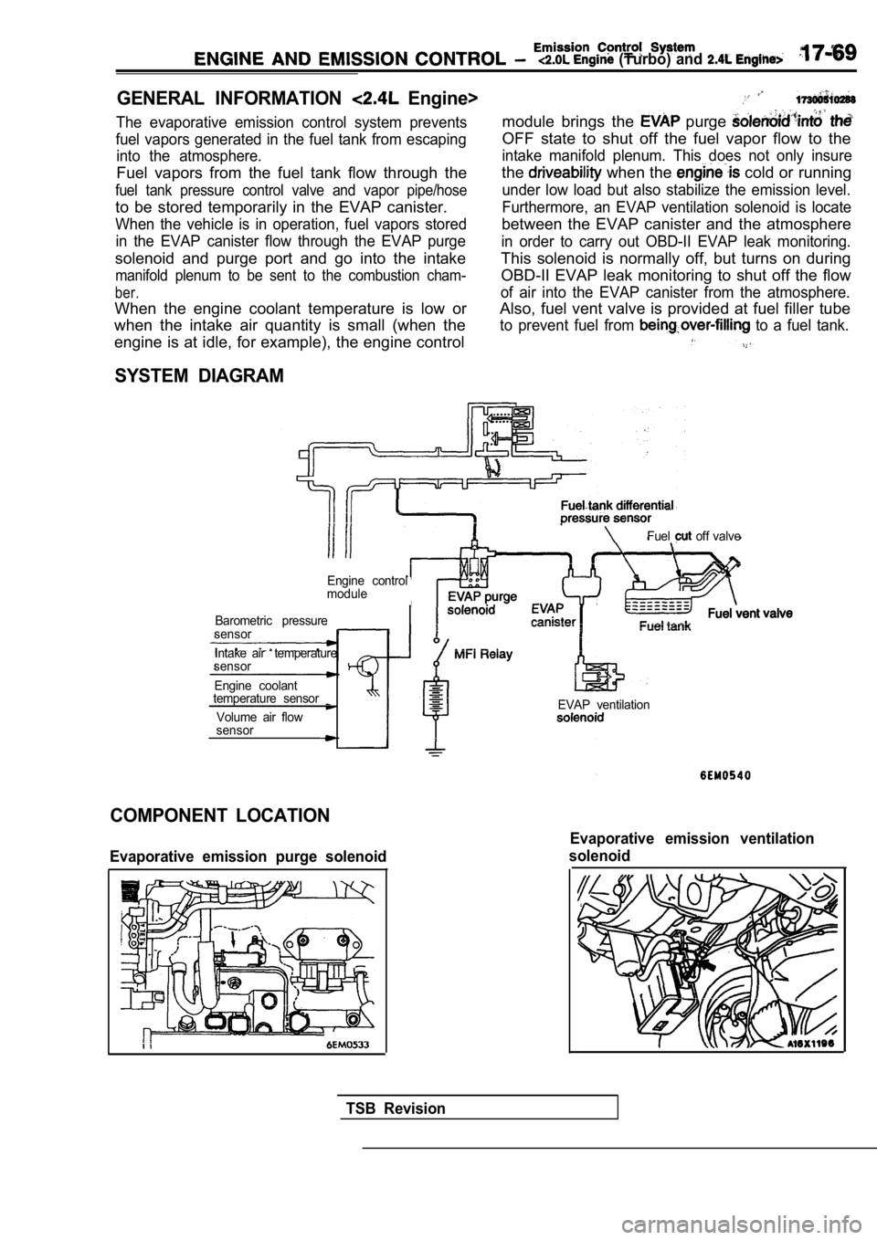
GENERAL INFORMATION Engine>
The evaporative emission control system prevents
fuel vapors generated in the fuel tank from escapin g
into the atmosphere.
Fuel vapors from the fuel tank flow through the
fuel tank pressure control valve and vapor pipe/hos e
to be stored temporarily in the EVAP canister.
When the vehicle is in operation, fuel vapors stored
in the EVAP canister flow through the EVAP purge
solenoid and purge port and go into the intake
manifold plenum to be sent to the combustion cham-
ber.
When the engine coolant temperature is low or
when the intake air quantity is small (when the
module brings the purge
OFF state to shut off the fuel vapor flow to the
intake manifold plenum. This does not only insure
the when the cold or running
under low load but also stabilize the emission leve l.
Furthermore, an EVAP ventilation solenoid is locate
between the EVAP canister and the atmosphere
in order to carry out OBD-II EVAP leak monitoring.
This solenoid is normally off, but turns on during
OBD-II EVAP leak monitoring to shut off the flow
of air into the EVAP canister from the atmosphere.
Also, fuel vent valve is provided at fuel filler tu be
to prevent fuel from to a fuel tank.
engine is at idle, for example), the engine control
SYSTEM DIAGRAM
Fuel off valve
Engine control
module
Barometric pressure
sensor
Intake air temperature
sensor
Engine coolant
temperature sensor
Volume air flow
sensorEVAP ventilation
COMPONENT LOCATION
Evaporative emission purge solenoid
Evaporative emission ventilation
solenoid
TSB Revision
Page 820 of 2103

(Turbo) and Engine>
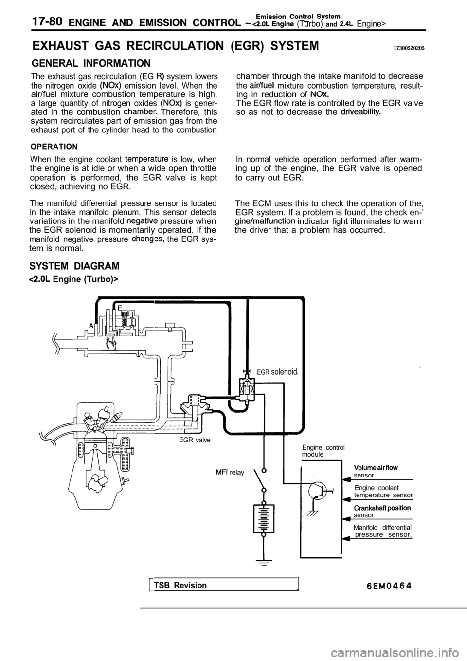
EXHAUST GAS RECIRCULATION
GENERAL INFORMATION
The exhaust gas recirculation (EG system lowers
the nitrogen oxide
emission level. When the
air/fuel mixture combustion temperature is high,
a large quantity of nitrogen oxides is gener-
ated in the combustion Therefore, this
system recirculates part of emission gas from the
exhaust port of the cylinder head to the combustion
OPERATION
When the engine coolant is low, when
the engine is at idle or when a wide open throttle
operation is performed, the EGR valve is kept
closed, achieving no EGR.
The manifold differential pressure sensor is locate d
in the intake manifold plenum. This sensor detects
variations in the manifold pressure when
the EGR solenoid is momentarily operated. If the
manifold negative pressure the EGR sys-
tem is normal.
SYSTEM DIAGRAM
Engine (Turbo)>
(EGR) SYSTEM17300520205
chamber through the intake manifold to decrease
the mixture combustion temperature, result-
ing in reduction of
The EGR flow rate is controlled by the EGR valve
so as not to decrease the
In normal vehicle operation performed after warm-
ing up of the engine, the EGR valve is opened
to carry out EGR.
The ECM uses this to check the operation of the, EGR system. If a problem is found, the check en-’
indicator light illuminates to warn
the driver that a problem has occurred.
EGR valve
relay
EGRsolenoid
Engine control
module
Isensor
Engine coolant
temperature sensor
sensor
Manifold differential
TSB Revision
pressure sensor,
Page 1312 of 2103
-Transaxle
Differential
bearing
retainer
a sliding hammer, etc., to remove the outer race.
all oil seals. ,
,
REASSEMBLY
(1)Using the special tool, install the oil seals to th e differential
bearing retainer and transaxle case.
(2) Use the special tool to press fit the
into the’
transaxle case.
(3) Install the transfer shaft.
(4) Place solder with a length of approximately 10 mm
in.) and diameter of 1.6 mm in.) on the output bearing
retainer at the position shown in the diagram and install
the outer race.
TSB Revision
Page 1323 of 2103
A U T O M A T I C T R A N S A X L E
OVERHAUL
the end clutch cover tighten the
specified torque.’
End cover mounting
assembly.
with a length mm
in.) and diameter of 1.6 mm in.) on the
rear bearing retainer at the position shown the diagram
and install the outer race.
the differential rear
the to the specified torque:
the bolts, remove the differential
remove the if solder is
repeat steps (51) using the solder with the diameter
of 3 mm.
Differential rear bearing retainer bolts:
35Nm (26
,
the of the
and adjust by selecting a
that will provide the value and
preload..
S t a n d a r d v a l u e :
,,
TSB Revision
Page 1325 of 2103
AUTOMATIC
OVERHAUL Transaxle
A
the oil temperature sensor into the
,
an O-ring in the O-ring groove at the top of ‘the
valve body assembly.
the solenoid valve harness grommet with
valve connector transaxle
case hole from the inside,
the solenoid valve harness the case
hole.
the knock pin of the valve body
keeping the detent plate pin in the manual groove.
Temporarily install the valve body,
the oil tempera-
ture sensor and holder; then tighten the
to the specified torque.
A 1 8
bolt: 40 mm (1.58 in.)
body assembly mounting 11
Caution
Firmly fasten the and temperature
sensor harness at the shown positions.
Especially, be sure to route the pressure
(PCSV) harness, which is separated from
other harness, as shown in the diagram and
the harness. Failure to fasten it may result in con tact
with the detent plate or parking rod.
TSB Revision
Page 1328 of 2103
AUTOMATIC TRANSAXLE
OVERHAUL
Transaxle
the lock nut by hand until it touches the
Then, use torque wrench the lock nut
specified torque.
Lock nut: 29 Nm (21
Caution Caution
The lock nut may turn- with the The lock nut may turn- with the
tightened quickly, or tightened quickly, or
wrench.
wrench.
(g)Remove the special tool for securing the piston.
the plug to the pressure outlet and tight-
en to the specified torque.
ring. the
servo switch and fasten with a snap
,
the oil pump drive hub with automatic transmission
,
fluid and install the torque. converter. in firmly
that dimension A in the diagram is at the standard value.
Standard value: 16.3
TSB Revision