Page 1349 of 2103
AUTOMATIC TRANSAXLE
OVERHAUL
Transaxle
the air exhaust plug, and then install the
Air exhaust plug: 33 Nm (24
the anchor rod.
the servo piston and sleeve.’
Caution
The seal ring alignment hole of the
servo
piston must not overlap the oil filler port (indica ted
by the arrow in the diagram).
the special tool to push in the servo piston
and sleeve, and then install a snap ring.
the band.
Caution
Install so the arrow mark
facing forward.
TSB Revision
Page 1356 of 2103
AUTOMATIC TRANSAXLE
OVERHAUL -Transaxle
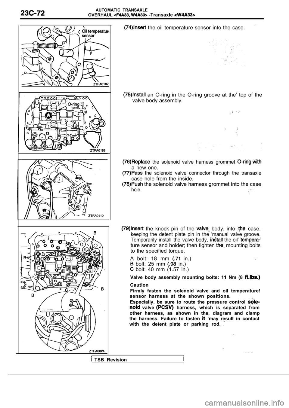
the oil temperature sensor into the case.
an O-ring in the O-ring groove at the’ top of the
valve body assembly.
the solenoid valve harness grommet
a new one.
the solenoid valve connector through the transaxle
case hole from the inside.
the solenoid valve harness grommet into the case
hole.
the knock pin of the body, into case,
keeping the detent plate pin in the ‘manual valve g roove.
Temporarily install the valve body,
the oil’
ture sensor and holder; then tighten mounting bolts
to the specified torque.
A bolt: 18 mm
in.)
bolt: 25 mm in.)
bolt: 40 mm (1.57 in.)
Valve body assembly mounting bolts: 11 Nm (8
Caution
Firmly fasten the solenoid valve and oil temperatur e!
sensor harness at the shown positions.
Especially, be sure to route the pressure control
valve harness, which is separated from
other harness, as shown in the, diagram and clamp
the harness. Failure to fasten
‘may result in contact
with the detent plate or parking rod.
TSB Revision
Page 1359 of 2103
AUTOMATIC TRANSAXLE
OVERHAUL -Transaxle
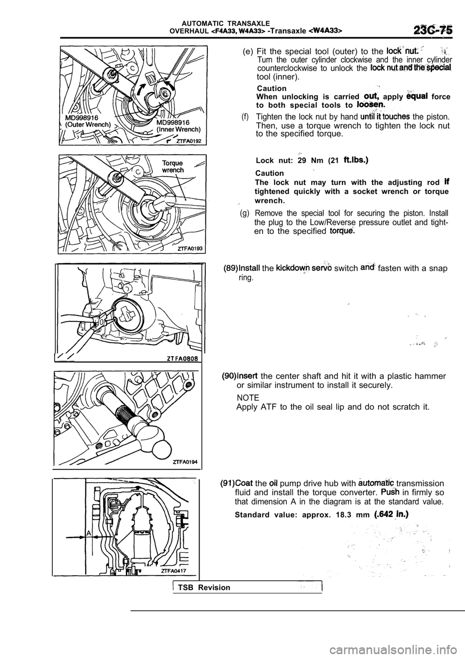
(e) Fit the special tool (outer) to the
Turn the outer cylinder clockwise and the inner cyl inder
counterclockwise to unlock the
tool (inner).
Caution
When unlocking is carried
apply force
to both special tools to
(f)Tighten the lock nut by hand the piston.
Then, use a torque wrench to tighten the lock nut
to the specified torque.
Lock nut: 29 Nm (21
Caution
The lock nut may turn with the adjusting rod
tightened quickly with a socket wrench or torque
wrench.
(g) Remove the special tool for securing the piston. In stall
the plug to the Low/Reverse pressure outlet and tight-
en to the specified
the switch fasten with a snap
ring.
the center shaft and hit it with a plastic hammer
or similar instrument to install it securely.
NOTE
Apply ATF to the oil seal lip and do not scratch it .
the pump drive hub with transmission
fluid and install the torque converter.
in firmly so
that dimension A in the diagram is at the standard value.
Standard value: approx. 18.3 mm
TSB Revision
Page 1506 of 2103
GENERAL INFORMATION
FRONT AXLE General Specification/Lubricants
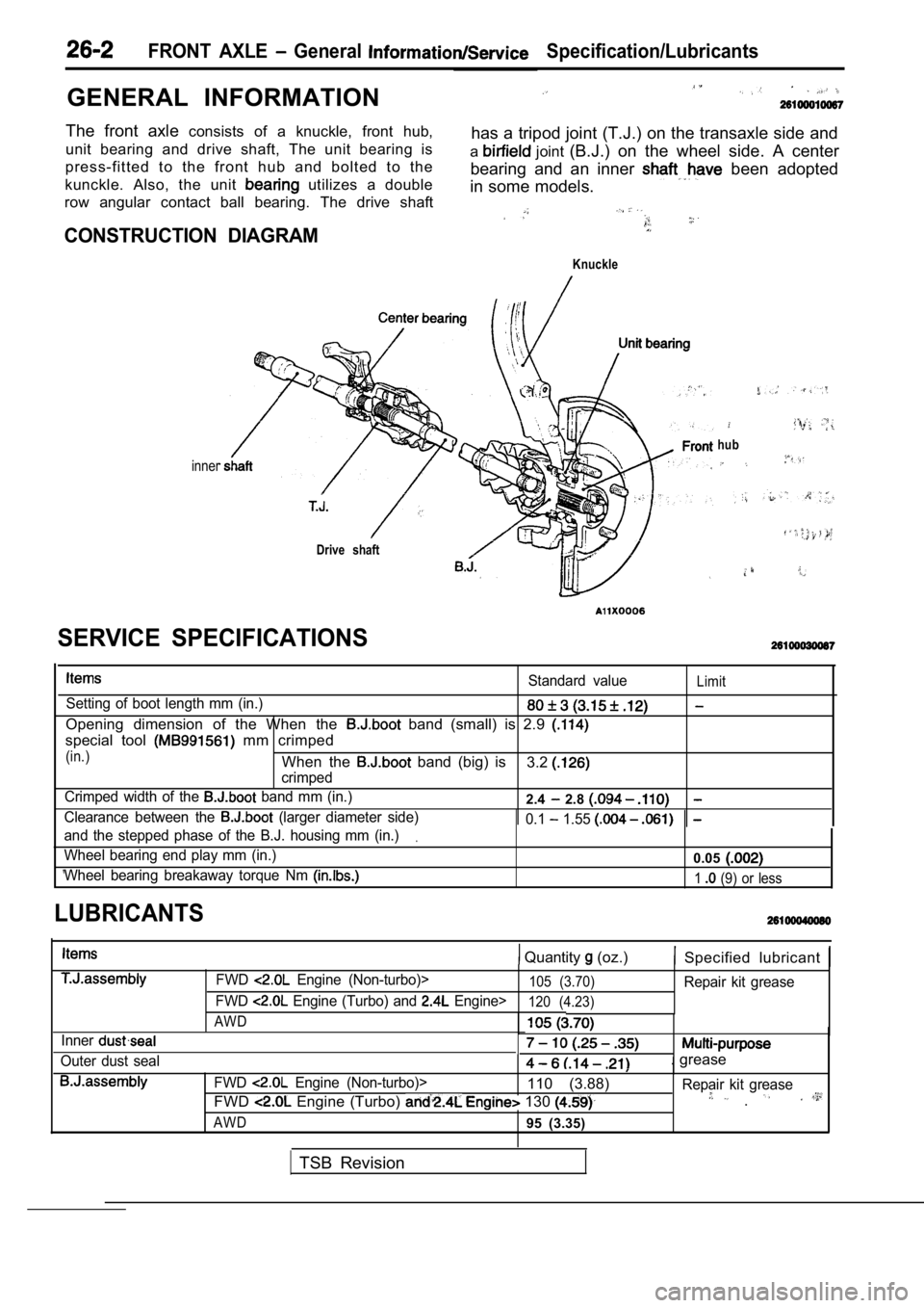
The front axle consists of a knuckle, front hub,
unit bearing and drive shaft, The unit bearing is has a tripod joint (T.J.) on the transaxle side and
press-fitted to the front hub and bolted to the a
joint
(B.J.) on the wheel side. A center
kunckle. Also, the unit
utilizes a double bearing and an inner been adopted
in some models.
row angular contact ball bearing. The drive shaft
CONSTRUCTION DIAGRAM
Knuckle
inner
Drive shaft
hub
Standard valueLimit
Setting of boot length mm (in.)
Opening dimension of the When the band (small) is 2.9
special tool mm crimped
(in.)When the band (big) is
crimped3.2
Crimped width of the band mm (in.)2.4 2.8
Clearance between the (larger diameter side) 0.1 1.55
and the stepped phase of the B.J. housing mm (in.).
Wheel bearing end play mm (in.)0.05
Wheel bearing breakaway torque Nm 1 (9) or less
SERVICE SPECIFICATIONS
LUBRICANTS
Quantity (oz.) Specified lubricant
Inner
Outer dust sealFWD
Engine (Non-turbo)>105 (3.70)Repair kit grease
FWD
Engine (Turbo) and Engine>120 (4.23)
AWD
. grease
FWD Engine (Non-turbo)>110 (3.88) Repair kit grease
FWD Engine (Turbo) 130 .
AWD95 (3.35)
TSB Revision
Page 1543 of 2103
REAR AXLE General Information.
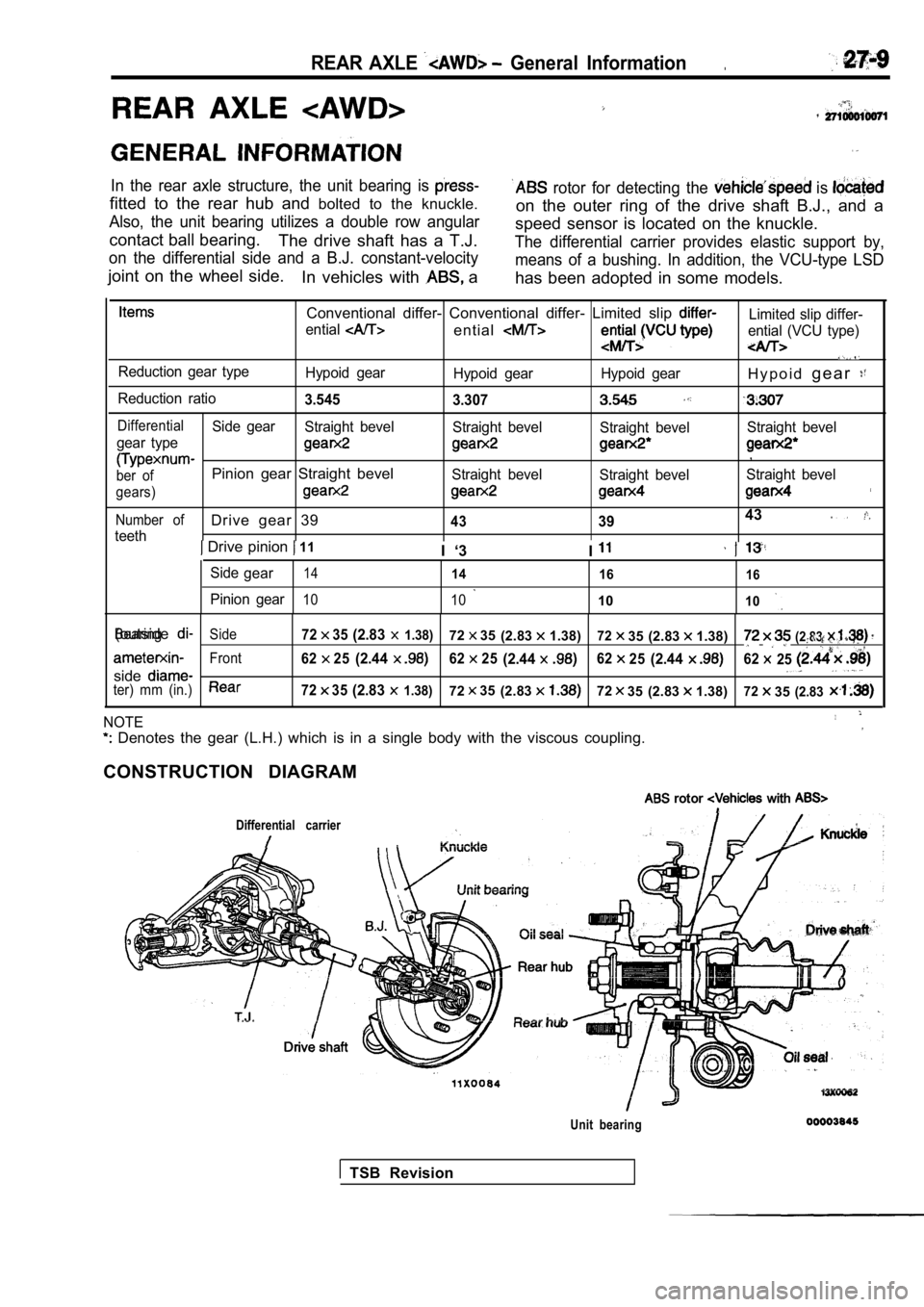
In the rear axle structure, the unit bearing is
fitted to the rear hub and bolted to the knuckle.
Also, the unit bearing utilizes a double row angula r
contact ball bearing.
The drive shaft has a T.J.
on the differential side and a B.J. constant-veloci ty
joint on the wheel side.
In vehicles with a
rotor for detecting the is
on the outer ring of the drive shaft B.J., and a
speed sensor is located on the knuckle.
The differential carrier provides elastic support b y,
means of a bushing. In addition, the VCU-type LSD
has been adopted in some models.
Conventional differ- Conventional differ- Limited s lip Limited slip differ-
ential
entialential (VCU type)
Reduction gear type Hypoid gearHypoid gear Hypoid gearH y p o i dg e a r
Reduction ratio3.545
3.307
DifferentialSide gearStraight bevel Straight bevelStraight bevelStraight bevel
gear type
,
ber ofPinion gear Straight bevelStraight bevel Straight bevelStraight bevel
gears)
Number ofDrive gear 39433943
teeth Drive pinion 11
I ‘3 I
Sidegear1414 1616
Pinion gear10 101010
BearingSide7235(2.83 1.38)7235(2.831.38)7235 (2.83 1.38)(outside(2.83 ,
Front6225(2.446225(2.446225(2.4462 25
sideter) mm (in.)7235(2.83 1.38)7235(2.837235 (2.83 1.38)72 35(2.83
NOTE
Denotes the gear (L.H.) which is in a single body with the viscous coupling.
CONSTRUCTION DIAGRAM
rotor with
Differential carrier
Unit bearing
TSB Revision
Page 1640 of 2103
BRAKE SYSTEM General Information
G E N E R A L I N F O R M A T I O N
. , . .
SERVICE BRAKES
The brake system has high
which maintains excellent braking performance.
has been adopted as the front
The main features are as follows. Floating caliper, double-piston and
l A dual type master cylinder is equipped on
disc
all models.
l Both a single type and a tandem type
c a l i p e r , s i n g l e - p i s t o n a n d
disc
booster have been adopted.l Disc has been adopted as the rear
brakes. [Floating caliper, single-piston and solid
disc
NOTE
Vehicles with ABS.
CONSTRUCTION DIAGRAM
, Front
TSB Revision
Page 1690 of 2103
ABS General Information
The ABS consists of wheel speed sensors, stop light switch, hydraulic unit and the ABS-ECU. If
a problem occurs in the system, the malfunctioning
system can be identified by means of the diagnostic
function.
The diagnostic trouble code will not be erased even
if the ignition switch is turned to OFF.
In addition, reading of diagnostic trouble codes,
service testing are possible using
t h e s c a n
Items
Wheel speed sensor
Front ABS rotor teeth
Rear ABS rotor teeth
,
Magnet coil type
4 3
43
DIAGRAM
1. ABS-ECU6. ABS rotor7. Data link connector .
6. Stop
9. ABS warning light
2. Hydraulic unit
3. ABS valve relay
4. ABS motor relay
5. Wheel speed sensor
TSB Revision
Page 1715 of 2103
A B S
HYDRAULIC UNIT (HU) CHECK
Caution
35200170111
Turn the ignition switch off before connecting ordisconnecting the scan tool.
1.
up the vehicle and support the vehicle with rigid
racks placed at the specified jack-up points or pla ce the
wheels which are checked on the rollers of the brak ing
force tester.
Caution
1.The roller of the braking force tester and the tire
be dry during testing.
2.When testing the front brakes, apply the parking
brake, and when testing the rear brakes, stop the
front by chocking them.
2.Release the parking brake, and feel the drag force (drag
torque) on each road wheel.. __
When using the braking force tester, take a reading of’
the brake drag force.
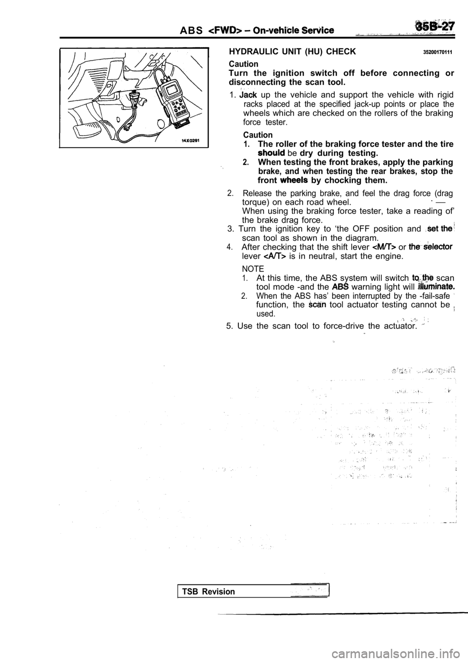
3. Turn the ignition key to ‘the OFF position and
scan tool as shown in the diagram.
4.After checking that the shift lever or
lever is in neutral, start the engine.
NOTE
1.At this time, the ABS system will switch scan
tool mode -and the
warning light will
2.When the ABS has’ been interrupted by the -fail-saf e
function, the tool actuator testing cannot be
used.
5. Use the scan tool to force-drive the actuator.
TSB Revision