1990 MITSUBISHI SPYDER width
[x] Cancel search: widthPage 30 of 2103
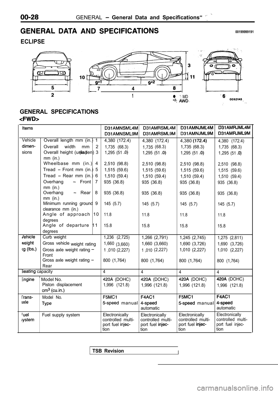
GENERAL General Data and Specifications“
00199999191
ECLIPSE
74
1l ‘: MD
.
GENERAL SPECIFICATIONS
VehicleOverall length mm (in.) 14,380 (172.4)4,380 (172.4)4,3804,380 (172.4)
Overall width mm 21,735 (68.3) 1,735
sions(in.) (68.3)
1,735 (68.3)1,735 (68.3)
Overall height (unladen) 31,295 (51 1,295 (51 1,295 (51 1,295(51
mm (in.)
W h e e l b a s e m m ( i n . ) 42,510 (98.8)
2,510 (98.8)2,510 (98.8)2,510 (98.8)
Tread Front mm (in.) 51,515 (59.6)
1,515 (59.6) 1,515 (59.6)1,515 (59.6)
Tread Rear mm (in.) 61,510 (59.4)
1,510 (59.4) 1,510 (59.4)1,510 (59.4)
Overhang Front 7935 (36.8)
935 (36.8) 935 (36.8)935 (36.8)
mm (in.)
Overhang Rear 8935 (36.8) 935 (36.8) 935 (36.8)935 (36.8)
mm (in.)
Minimum running ground 9145 (5.7) 145 (5.7) 145 (5.7)145 (5.7)
clearance mm (in.)
A n g l e o f a p p r o a c h 1 011.8 11.8 11.811.8
degrees
A n g l e o f d e p a r t u r e 1 115.8
15.8 15.815.8
degrees
Curb weight1,236 (2,725)1,266 (2,791) 1,245 (2,745)1,275 (2,811)
Gross vehicle
weight rating1,660(3,660)1,660 (3,660) 1,690 (3,726)1,690 (3,726)
Gross axle weight rating1 ,010 (2,227)1 ,010(2,227)1,010 (2,227)1,010 (2,227)
Front
Gross axle weight rating
800 (1,764) 800 (1,764) 800 (1,764)800 (1,764)
Rear
capacity4 4 44
Model No. (DOHC) (DOHC) (DOHC) (DOHC)
Piston displacement
1,996 (121.8)1,996 (121.8) 1,996 (121.8)1,996 (121.8)
Model No.
m a n u a l m a n u a l
automatic automatic
Fuel supply system
Electronically
Electronically ElectronicallyElectronically
controlled multi- controlled multi- controlled multi-controlled multi-
port fuel port fuel port fuel port fuel injec-
tion
tion tiontion
TSB RevisionI
Page 31 of 2103
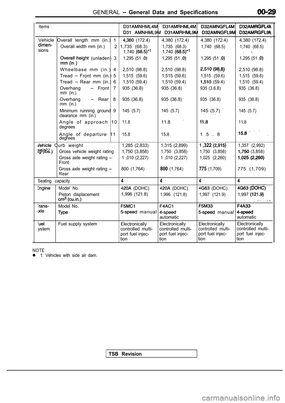
GENERAL General Data and Specifications
Items
,Vehicle Overall length mm (in.) 1 (172.4) 4,380 (172.4) 4,380 (172.4) 4,380 (172.4)
sionsOverall width mm (in.)2 1,735 (68.3)
1,740
1,735 (68.3)
1,740
1,740 (68.5) 1,740 (68.5)
(unladen) 31,295 (51 1,295 (51 1,295 (51 1,295 (51
W h e e l b a s e m m ( i n . ) 42,510 (98.8) 2,510 (98.8)2,510 (98.8)
Tread Front mm (in.) 51,515 (59.6)1,515 (59.6)1,515 (59.6) 1,515 (59.6)
Tread Rear mm (in.) 61,510 (59.4) 1,510 (59.4) (59.4)1,510 (59.4)
Overhang Front 7935 (36.8) 935 (36.8)935 (3.6.8) 935 (36.8)
mm (in.)
Overhang Rear 8935 (36.8) 935 (36.8)935 (36.8) 935 (36.8)
mm (in.)
Minimum running ground 9145 (5.7) 145 (5.7)145 (5.7) 145 (5.7)
clearance mm (in.)
A n g l e o f a p p r o a c h 1 011.811.811.8
degrees
A n g l e o f d e p a r t u r e 1 115.8 15.81 5 . 8degrees
Curb weight1,285 (2,833) 1,315 (2,899) ,322 1,357 (2,992)
Gross vehicle weight rating 1,750 (3,858)1,750 (3,858) 1,750 (3,858)(3,858)
Gross axle weight rating 1 ,010 (2,227) 1 ,010 (2,227) 1,025 (2,260)
Front
Gross axle weight rating 800 (1,764)800(1,764)775(1,709)775 (1,709)
Rear
Seating capacity
Model No.
Piston displacement
Model No.
Fuel supply system
ystem
4 444
(DOHC) (DOHC) (DOHC)
1,996 (121.8)1,996 (121.8) 1,997 (121.9)1,997
m a n u a l manual
automatic automatic
Electronically Electronically Electronically Electronically
controlled multi- controlled multi-
controlled multi-controlled multi-
port fuel injec- port fuel injec-port fuel injec-
port fuel injec-
tion tion tion tion
NOTE
l 1: Vehicles with side air dam.
TSB Revision
Page 32 of 2103
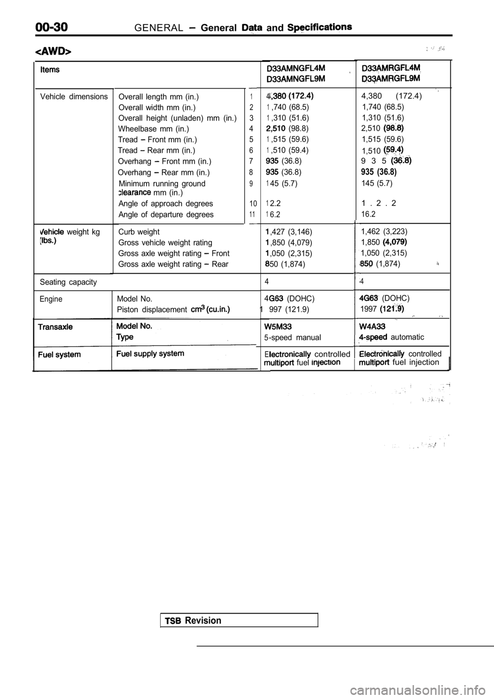
GENERAL General and
Vehicle dimensions
weight kg
Overall length mm (in.)
Overall width mm (in.)
Overall height (unladen) mm (in.)
Wheelbase mm (in.)
Tread
Front mm (in.)
Tread
Rear mm (in.)
Overhang
Front mm (in.)
Overhang
Rear mm (in.)
Minimum running ground
mm (in.)
Angle of approach degrees
Angle of departure degrees
Curb weight
Gross vehicle weight rating
Gross axle weight rating
Front
Gross axle weight rating
Rear
1
2
3
4 5
6
7
8
9
10
11
Seating capacity
EngineModel No.
Piston displacement
4
1,740 (68.5)
1,310 (51.6)
(98.8)
1,515 (59.6)
1,510 (59.4)
(36.8)
(36.8)
145 (5.7)
4,380 (172.4)
1,740 (68.5)
1,310 (51.6)
2,510
1,515 (59.6)
1,510
9 3 5
935 (36.8)
145 (5.7)
12.2
16.2
,427 (3,146)
,850 (4,079)
,050 (2,315)
50 (1,874)
4
4
1
5
El
1 . 2 . 2
16.2
1,462 (3,223)
1,850
1,050 (2,315)
(1,874)
4
(DOHC)
997 (121.9)
-speed manual
(DOHC)
1997
automatic
controlled controlled
fuel fuel injection
Revision
Page 33 of 2103
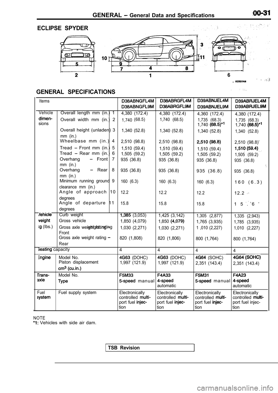
GENERAL General Data and Specifications
ECLIPSE SPYDER
GENERAL SPECIFICATIONS
6
.
Items
VehicleOverall length mm (in.) 14,380 (172.4) 4,380 (172.4)
4,360 (172.4)4,380 (172.4)
Overall width mm (in.) 21,740(68.5)
1,740 (68.5)
1,735 (68.3)1,7401,735 (68.3)sions
1,740
Overall height (unladen) 31,340 (52.8)1,340 (52.8)
1,340 (52.8)1,340 (52.8)
mm (in.)
W h e e l b a s e m m ( i n . ) 42,510 (98.8) 2,510 (98.8)2,510 (98.8)’
Tread Front mm (in.) 51,510 (59.4) 1,510 (59.4)
1,510 (59.4)
Tread Rear mm (in.) 61,505 (59.2) 1,505 (59.2)
1,505 (59.2)1,505 (59.2)Overhang Front 7935 (36.8) 935 (36.8)
935 (36.8)935 (36.8)
mm (in.)
Overhang Rear 8935 (36.8) 935 (36.8)9 3 5 ( 3 6 . 8 )935 (36.8)
mm (in.)
Minimum running ground 9160 (6.3) 160 (6.3)
160 (6.3)1 6 0 ( 6 . 3 )
clearance mm (in.)
A n g l e o f a p p r o a c h 1 012.2 12.2
12.21 2 . 2
degrees
A n g l e o f d e p a r t u r e 1 115.8 15.8
15.81 5 . 6 ’
degrees
Curb weight (3,053)1,425 (3,142)1,305 (2,877) 1,335 (2,943)
Gross vehicle
1,765 (3,935)1,785 (3,935)
(Ibs.)weight rating1,850 (4,079)
1,850Gross axle weight rating 1,030 (2,271)1,030 (2,271)1 ,010 (2,227) 1,010 (2,227)
Front
Gross axle weight rating
820 (1,808) 820 (1,806)
800 (1,764)800 (1,764)
Rear
capacity
Model No.
Piston displacement
Model No.
FuelFuel supply system
NOTE
Vehicles with side air dam. 4
444
(DOHC) (DOHC) (SOHC)
1,997 (121.9)
1,997 (121.9)
2,351 (143.4)2,351 (143.4)
m a n u a l m a n u a l
automatic automatic
Electronically Electronically Electronically Electronically
controlled
controlledcontrolledcontrolled
port fuel port fuel port fuel port fuel injec-
tion tion tion tion
TSB Revision
Page 107 of 2103
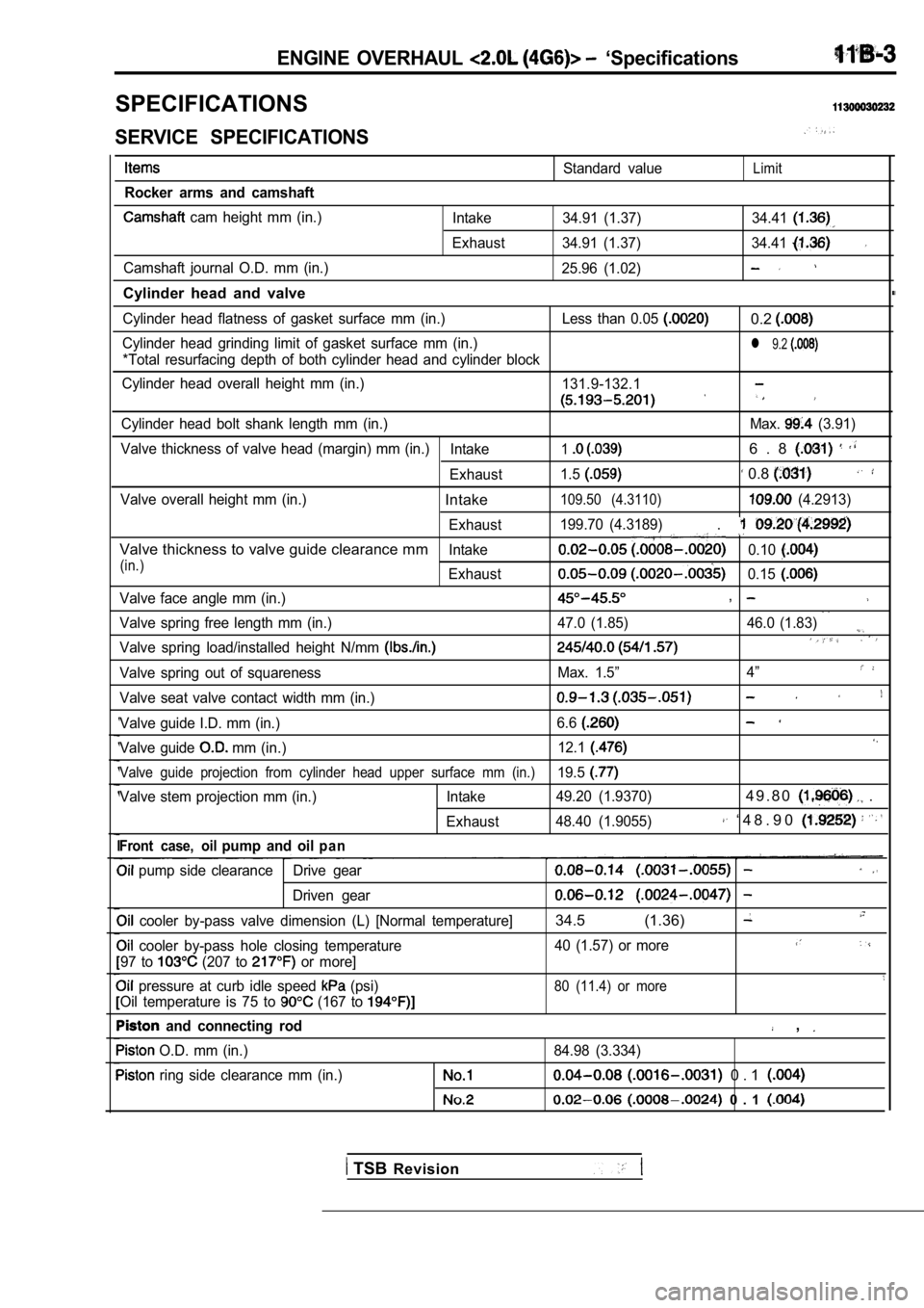
ENGINE OVERHAUL ‘Specifications
SPECIFICATIONS
SERVICE SPECIFICATIONS
Rocker arms and camshaft
cam height mm (in.)
Camshaft journal O.D. mm (in.)
Cylinder head and valve
Standard valueLimit
Intake 34.91 (1.37) 34.41
Exhaust 34.91 (1.37) 34.41
25.96 (1.02)
Cylinder head flatness of gasket surface mm (in.) Le ss than 0.05 0.2
Cylinder head grinding limit of gasket surface mm (in.)l 9.2
*Total resurfacing depth of both cylinder head and cylinder block
Cylinder head overall height mm (in.) 131.9-132.1
Cylinder head bolt shank length mm (in.) Max. (3.91)
Valve thickness of valve head (margin) mm (in.) Intake
16 . 8
Exhaust1.5 0.8
Valve overall height mm (in.)Intake109.50 (4.3110) (4.2913)
Exhaust 199.70 (4.3189)
.
Valve thickness to valve guide clearance mmIntake0.10
(in.)Exhaust0.15
Valve face angle mm (in.),
Valve spring free length mm (in.) 47.0 (1.85) 46.0 (1
.83)
Valve spring load/installed height N/mm
Valve spring out of squarenessMax. 1.5”4”
Valve seat valve contact width mm (in.)
Valve guide I.D. mm (in.) 6.6
Valve guide mm (in.)12.1
Valve guide projection from cylinder head upper sur
face mm (in.)19.5
Valve stem projection mm (in.) Intake 49.20 (1.9370)4 9 . 8 0 .
Exhaust48.40 (1.9055) ‘ 4 8 . 9 0
Front case, oilpump and oilp a n
pump side clearance Drive gear
Driven gear
cooler by-pass valve dimension (L) [Normal tempera
ture]34.5 (1.36)
cooler by-pass hole closing temperature 40 (1.57) or more
97 to (207 to or more]
pressure at curb idle speed (psi)80 (11.4) or more
Oil temperature is 75 to (167 to
and connecting rod ,
O.D. mm (in.)
84.98 (3.334)
ring side clearance mm (in.) 0 . 1
0 . 1
TSB Revision
Page 144 of 2103
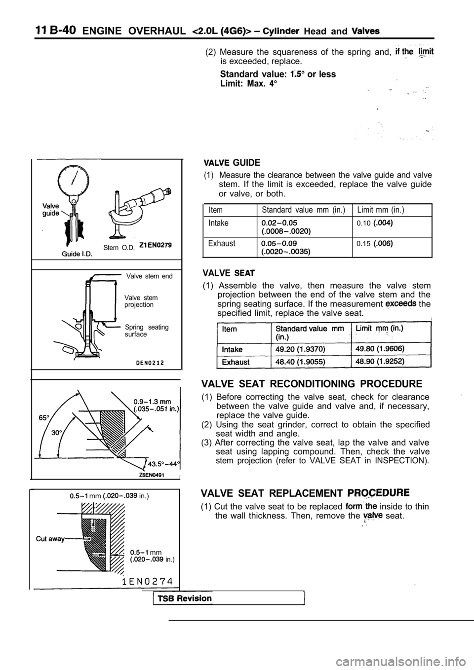
ENGINE OVERHAUL Head and
(2) Measure the squareness of the spring and,
is exceeded, replace.
Standard value: or less
Limit: Max.
Stem O.D.
Valve stem end
Valve stem
projection
Spring seating
surface
GUIDE
(1)Measure the clearance between the valve guide and v alve
stem. If the limit is exceeded, replace the valve guide
or valve, or both.
Item
Intake
Exhaust Standard value mm (in.) Limit mm (in.)0.10
0.15
VALVE
(1) Assemble the valve, then measure the valve stem
projection between the end of the valve stem and th e
spring seating surface. If the measurement
the
specified limit, replace the valve seat.
VALVE SEAT RECONDITIONING PROCEDURE
(1) Before correcting the valve seat, check for cle arance
between the valve guide and valve and, if necessary ,
replace the valve guide.
(2) Using the seat grinder, correct to obtain the s pecified
seat width and angle.
(3) After correcting the valve seat, lap the valve and valve
seat using lapping compound. Then, check the valve
stem projection (refer to VALVE SEAT in INSPECTION) .
VALVE SEAT REPLACEMENT
(1) Cut the valve seat to be replaced inside to thin
the wall thickness. Then, remove the
seat..
I
mm in.)
mm in.)
Page 145 of 2103
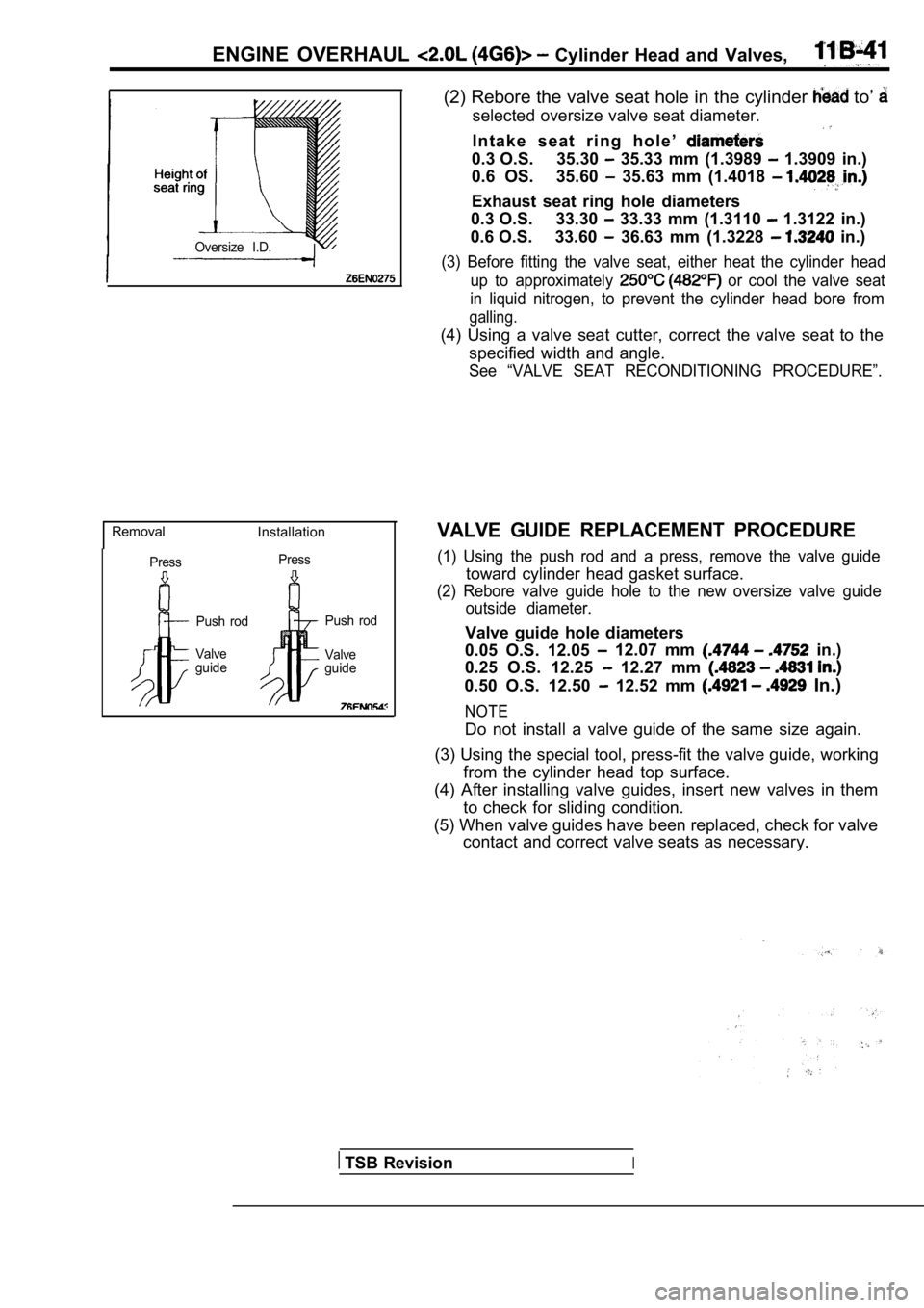
ENGINE OVERHAUL Cylinder Head and Valves,
Oversize I.D.
RemovalInstallation
PressPress
Push rod
Valve
guide Push rod
Valve
guide
(2) Rebore the valve seat hole in the cylinder to’
selected oversize valve seat diameter.
I n t a k e s e a t r i n g h o l e ’
0.3 O.S. 35.30 35.33 mm (1.3989 1.3909 in.)
0.6 OS. 35.60
35.63 mm (1.4018
Exhaust seat ring hole diameters
0.3 O.S. 33.30
33.33 mm (1.3110 1.3122 in.)
0.6 O.S. 33.60
36.63 mm (1.3228 in.)
(3) Before fitting the valve seat, either heat the cylinder head
up to approximately
or cool the valve seat
in liquid nitrogen, to prevent the cylinder head bo re from
galling.
(4) Using a valve seat cutter, correct the valve seat to the
specified width and angle.
See “VALVE SEAT RECONDITIONING PROCEDURE”.
VALVE GUIDE REPLACEMENT PROCEDURE
(1) Using the push rod and a press, remove the valv e guide
toward cylinder head gasket surface.
(2) Rebore valve guide hole to the new oversize valve guide
outside diameter.
Valve guide hole diameters
0.05 O.S. 12.05
12.07 mm in.)
0.25 O.S. 12.25
12.27 mm
0.50 O.S. 12.50 12.52 mm In.)
NOTE
Do not install a valve guide of the same size again .
(3) Using the special tool, press-fit the valve gui de, working
from the cylinder head top surface.
(4) After installing valve guides, insert new valve s in them
to check for sliding condition.
(5) When valve guides have been replaced, check for valve
contact and correct valve seats as necessary.
TSB RevisionI
Page 162 of 2103
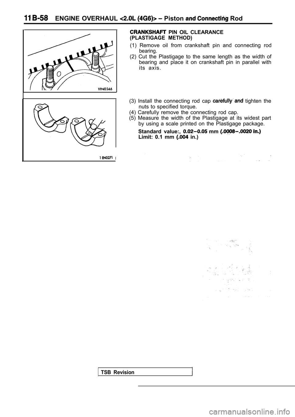
ENGINE OVERHAUL Piston Rod
1I
PIN OIL CLEARANCE
(PLASTIGAGE METHOD)
(1) Remove oil from crankshaft pin and connecting rod
bearing.
(2) Cut the Plastigage to the same length as the width of
bearing and place it on crankshaft pin in parallel with
i t s a x i s .
(3) Install the connecting rod cap
tighten the
nuts to specified torque.
(4) Carefully remove the connecting rod cap.
(5) Measure the width of the Plastigage at its wide st part
by using a scale printed on the Plastigage package.
Standard value:,
mm
Limit: 0.1 mm in.)
TSB Revision