1990 MITSUBISHI SPYDER width
[x] Cancel search: widthPage 430 of 2103
![MITSUBISHI SPYDER 1990 Service Repair Manual Scan tool 58
Code General scan tool Air Temperature Senspr
No.Voltage High
23
[Comment]Background
lWhen the fuel system is in the open mode, the heated oxygen sensor cannot MITSUBISHI SPYDER 1990 Service Repair Manual Scan tool 58
Code General scan tool Air Temperature Senspr
No.Voltage High
23
[Comment]Background
lWhen the fuel system is in the open mode, the heated oxygen sensor cannot](/manual-img/19/57345/w960_57345-429.png)
Scan tool 58
Code General scan tool Air Temperature Senspr
No.Voltage High
23
[Comment]Background
lWhen the fuel system is in the open mode, the heated oxygen sensor cannot be
used for injector pulse width calculation.
lIn this instance, the system uses on air mass to determine the correct pulse
width necessary to achieve the proper air/fuel rati o.
lBecause air mass is related to temperature, informa tion from the intake air temperature
sensor is necessary.
Range of Check
l Ignition switch: ON
Set Condition
l air temperature sensor output voltage is more than for 3
Check the intake air temperature sensor. (Refer to Replace
Measure at the intake air temperature sensor connec tor
lDisconnect the connector, and measure at the harness side.
l Continuity between and ground
OK: Continuity
OK
Sensor signal circuit open Sensor internally open
l Sensor ground circuit open
l PCM failed
Check the wire between the PCM the intake temperature connector. if necessary.
Check the following
OK
NG Repair
Check trouble symptom.
N G NGCheck the harness wire between the PCM and the inta ke air temperature sensor connector.
N G
Replace the PCM.
Repair
TSB Revision
Page 444 of 2103

ENGINE (NON-TURBO)> Troubleshooting’
Scan tool 113
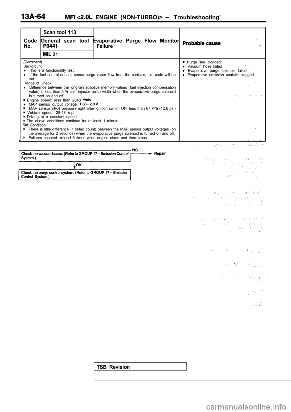
Code General scan tool Evaporative Purge Flow Monitor
No.
31
Failure
Purge line cloggedBackgroundl Vacuum hose failedl This is a functionality test.
l Evaporative purge solenoid failed lIf the fuel control doesn’t sense purge vapor flow from the canister, this code will be
l Evaporative emission cloggedset.Range of ChecklDifference between the long-ten adaptive memory val ues (fuel injection compensationvalue) is less than 5 shift injector pulse width when the evaporative purge solenoid
is turned on and off.
Engine speed: less than 2048 l MAP sensor output voltage: MAP sensor pressure right after ignition switch ON: lees than 87 (12.6 psi) Vehicle speed: 28-48 mph Driving at a constant speed The above conditions continue for at least 1 minut e. ConditionThere is little difference (1 failed count) between the MAP sensor output voltages (on .
the average for 2 seconds) when the evaporative pur ge solenoid is turned on and off.
Failures counted exceed 6 times while engine starts and then stops.
TSB Revision1
Page 447 of 2103
![MITSUBISHI SPYDER 1990 Service Repair Manual E N G I N E ( N O N - T U R B O ) >
Scan tool 118
C o d e
No. 72
[Comment]l Engine coolant temperature Backgroundl Intake air temperature sensor l The PCM monitors the fuel system MITSUBISHI SPYDER 1990 Service Repair Manual E N G I N E ( N O N - T U R B O ) >
Scan tool 118
C o d e
No. 72
[Comment]l Engine coolant temperature Backgroundl Intake air temperature sensor l The PCM monitors the fuel system](/manual-img/19/57345/w960_57345-446.png)
E N G I N E ( N O N - T U R B O ) >
Scan tool 118
C o d e
No. 72
[Comment]l Engine coolant temperature Backgroundl Intake air temperature sensor l The PCM monitors the fuel system for compliance wit h emission standards:’
l Head gasket ‘failed Range of Checkl Engine coolant temperature is greater than l Exhaust manifold cracked , l , Injectors failedl Closed loop operation
l MAP sensor failed .
Set Condition l Heated oxygen sensor failed,
l The test fails if the fuel control system reduces p ulse width by 25% long l regulator and 7% short term compensation due to a rich condit ion. W i r i n g failed
l Incorrect fuel used
l PCM failed
N G
05 Engine coolant temperature sensor. (Refer to
NGSCAN TOOL SENSOR READ
27 Intake air temperature sensor (Refer to
NGSCAN TOOL SENSOR READ TESTS (Data list)
11 MAP sensor reading (Refer to
OK
Check the engine coolant temperature circuit. INSPECTION -PROCEDURE 38.) . ., , ,
. - -
Check the intake air temperature circuit. (Refer t o INSPECTION PROCEDURE 39.)
Check the MAP sensor circuit. (Refer to INSPECTION
PROCEDURE
SCAN TOOL SENSOR READ TESTS (Data list)
63 Oxygen sensor volts (rear) (Refer to
l Transaxle: gear range l Drive with wide-open throttle
O K :
heatedoxygen circuit. PROCEDURE 41.) ,
OK
SCAN TOOL SENSOR READ TESTS (Data list)
02 Oxygen sensor volts (front) (Refer to
OK: during sudden racingINSPECTION PROCEDURE 42.) ,
SCAN TOOL SENSOR READ OK
Oxygen sensor volts (front) (Refer
OK
Check the following items.l Check the injectors for operation sound.
l Check the injectors for leakage.
l Check the evaporative emission control system.
l Check for contamination (water, kerosene, etc.) in the fuel.
TSB Revision
Page 448 of 2103
![MITSUBISHI SPYDER 1990 Service Repair Manual ENGINE (NON-TURBO)> Troubleshooting
Scan tool 119
Code General scan tool
No. 71Fuel System LeanProbable
51
[Comment]l Engine coolant temperature sensor Backgroundl The PCM monitor MITSUBISHI SPYDER 1990 Service Repair Manual ENGINE (NON-TURBO)> Troubleshooting
Scan tool 119
Code General scan tool
No. 71Fuel System LeanProbable
51
[Comment]l Engine coolant temperature sensor Backgroundl The PCM monitor](/manual-img/19/57345/w960_57345-447.png)
ENGINE (NON-TURBO)> Troubleshooting
Scan tool 119
Code General scan tool
No. 71Fuel System LeanProbable
51
[Comment]l Engine coolant temperature sensor Backgroundl The PCM monitors the fuel system for compliance wit h emission standards.l
Intake air temperature sensor failed- l Head gasket Range of Check
l Exhaust manifold cracked
l Engine coolant temperature is greater than l Injectors failed
l Closed loop operation
l MAP sensor failed
Set Condition
l Heated oxygen sensor failedlThe test fails if the fuel control system increases pulse width by 25% long term memory
and 12% short term compensation due to a lean condi tion.l
Fuel pressure regulator l l Fuel filter or fuel line blocked
l Fuel pump failed (insufficient discharge)
l Incorrect fuel used
__
l PCM failed
NGSCAN TOOL SENSOR READ TESTS (Data list)
05 Engine coolant temperature sensor (Refer to
SCAN TOOL SENSOR READ 27 Intake air temperature sensor to
SCAN TOOL SENSORREAD11 MAP sensor reading (Refer to
I
NG
Check the engine coolant temperature circuit.
(Refer to INSPECTION PROCEDURE 38.)
Check the intake air temperature circuit.(Refer to PROCEDURE 39.)
Check the MAP sensor circuit.
( R e f e r
63 Oxygen sensor volts (rear) (Refer to l Transaxle: gear range
SCAN TOOL SENSOR READ TESTS (Data list)
02 Oxygen sensor volts (front) (Refer to
OK: during sudden racing
NG Check the heated oxygen sensor (front) circuit.(Refer to INSPECTION PROCEDURE 42.)
SCAN TOOL SENSOR READ TESTS (Data list)
02 Oxygen sensor volts (front) (Refer to
OK: Repeat and alternately whenidling.
Check the fuel pressure. (Refer to
OK
Check the following items.
l Check the injectors for operation sound.
,
l Clean the injectors.
l Check the positive crankcase ventilation system.
l Check the fuel pump.
lCheck the fuel filter and fuel line for blockages.
l Check for exhaust gas leaks.
l Check for contamination (water, kerosene, etc.) in the fuel.
TSB Revision
Page 790 of 2103

ENGINE AND EMISSION CONTROL
EVAPORATIVE EMISSION CONTROL SYSTEM17300510271
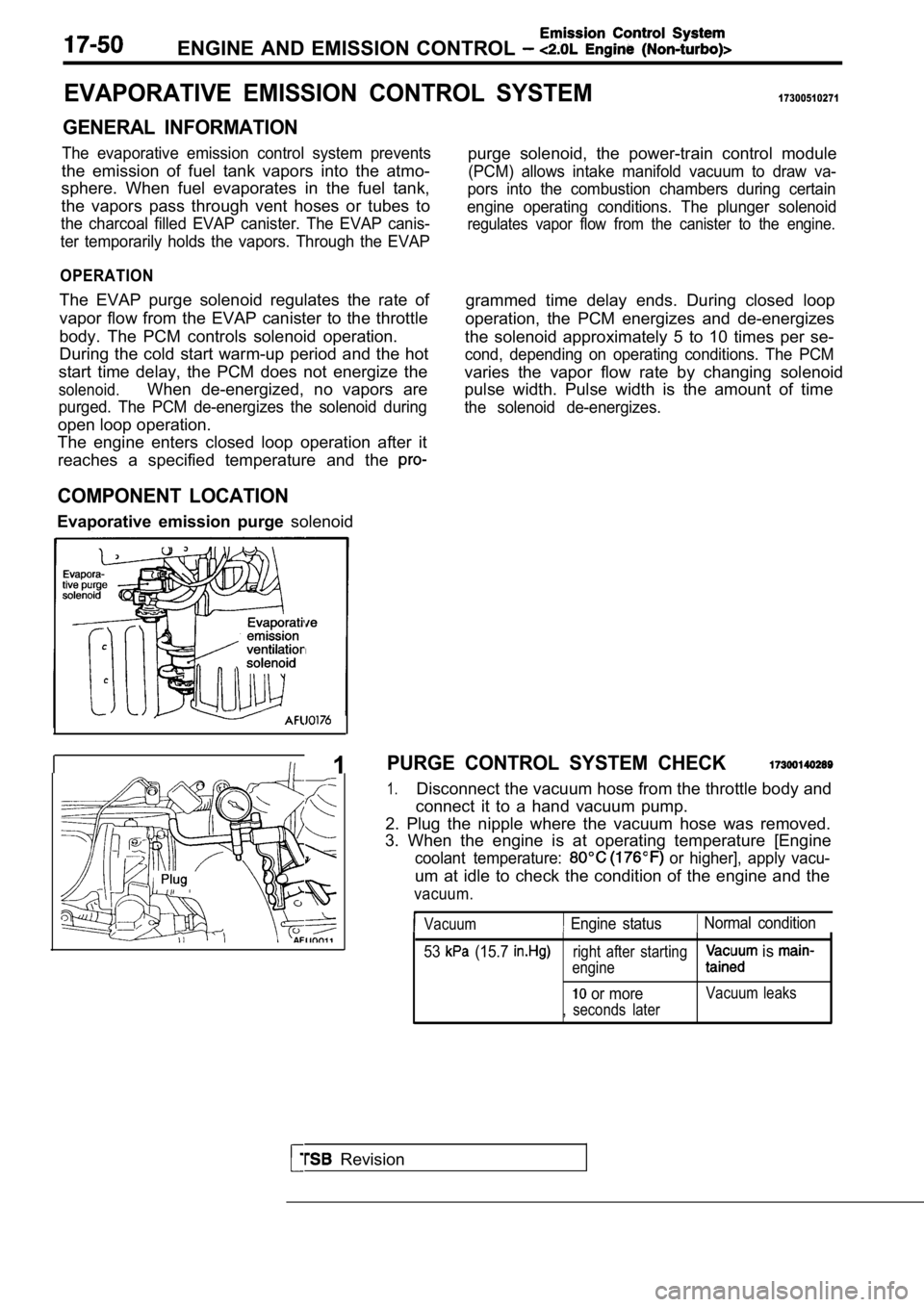
GENERAL INFORMATION
The evaporative emission control system prevents
the emission of fuel tank vapors into the atmo-
sphere. When fuel evaporates in the fuel tank,
the vapors pass through vent hoses or tubes to
the charcoal filled EVAP canister. The EVAP canis-
ter temporarily holds the vapors. Through the EVAP
OPERATION
The EVAP purge solenoid regulates the rate of
vapor flow from the EVAP canister to the throttle
body. The PCM controls solenoid operation.
During the cold start warm-up period and the hot
start time delay, the PCM does not energize the
solenoid.When de-energized, no vapors are
purged. The PCM de-energizes the solenoid during
open loop operation.
The engine enters closed loop operation after it
reaches a specified temperature and the
COMPONENT LOCATION
Evaporative emission purge solenoidpurge solenoid, the power-train control module
(PCM) allows intake manifold vacuum to draw va-
pors into the combustion chambers during certain
engine operating conditions. The plunger solenoid
regulates vapor flow from the canister to the engin e.
grammed time delay ends. During closed loop
operation, the PCM energizes and de-energizes
the solenoid approximately 5 to 10 times per se-
cond, depending on operating conditions. The PCM
varies the vapor flow rate by changing solenoid
pulse width. Pulse width is the amount of time
the solenoid de-energizes.
Revision
I 1PURGE CONTROL SYSTEM CHECK
1.Disconnect the vacuum hose from the throttle body a nd
connect it to a hand vacuum pump.
2. Plug the nipple where the vacuum hose was remove d.
3. When the engine is at operating temperature [Eng ine
coolant temperature: or higher], apply vacu-
um at idle to check the condition of the engine and the
vacuum.
Vacuum Engine status Normal condition
53
(15.7 right after starting
engine is
or moreVacuum leaks
, seconds later
Page 1506 of 2103

GENERAL INFORMATION
FRONT AXLE General Specification/Lubricants
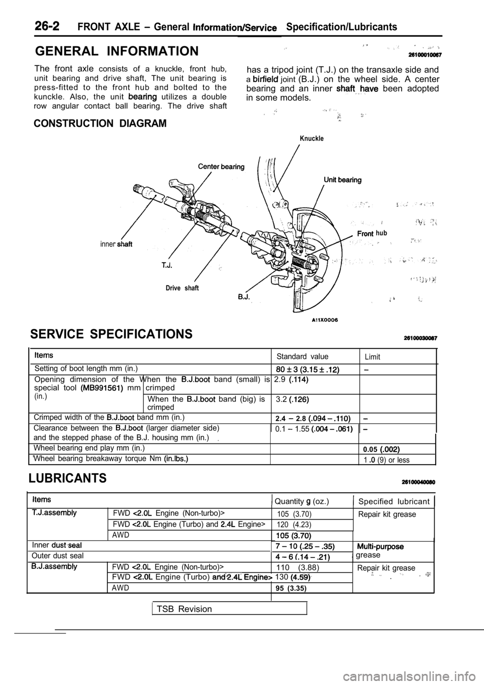
The front axle consists of a knuckle, front hub,
unit bearing and drive shaft, The unit bearing is has a tripod joint (T.J.) on the transaxle side and
press-fitted to the front hub and bolted to the a
joint
(B.J.) on the wheel side. A center
kunckle. Also, the unit
utilizes a double bearing and an inner been adopted
in some models.
row angular contact ball bearing. The drive shaft
CONSTRUCTION DIAGRAM
Knuckle
inner
Drive shaft
hub
Standard valueLimit
Setting of boot length mm (in.)
Opening dimension of the When the band (small) is 2.9
special tool mm crimped
(in.)When the band (big) is
crimped3.2
Crimped width of the band mm (in.)2.4 2.8
Clearance between the (larger diameter side) 0.1 1.55
and the stepped phase of the B.J. housing mm (in.).
Wheel bearing end play mm (in.)0.05
Wheel bearing breakaway torque Nm 1 (9) or less
SERVICE SPECIFICATIONS
LUBRICANTS
Quantity (oz.) Specified lubricant
Inner
Outer dust sealFWD
Engine (Non-turbo)>105 (3.70)Repair kit grease
FWD
Engine (Turbo) and Engine>120 (4.23)
AWD
. grease
FWD Engine (Non-turbo)>110 (3.88) Repair kit grease
FWD Engine (Turbo) 130 .
AWD95 (3.35)
TSB Revision
Page 1520 of 2103

F R O N T Drive Shaft
561
Stopper
Adjusting bolt
0 0 0 0 3 4 2 0
protruding portion
0 0 0 0 3 4 2 1
0 0 0 0 3 4 2 2(3)
the ajustingbolt of the special tool to adjust the
opening dimension (W) to the standard value.
Standard
2.9 mm in.)
more than 2.9 mm in.)>
Screw in the adjusting bolt.
Loosen the adjusting bolt.
NOTE
(1) The dimension (W) is adjusted by approx. 0.7 mm
in.) per one turn.
(2) Do not turn the adjusting bolt more
one turn.
(4) Place the boot band (small) along the protrudin g
and install it so that there is some (A)
the other side. . .
(5) ‘Use the special tool to crimp the B.J. boot
Caution
(1) Hold the drive shaft perpendicularly, and use t he
special tool to crimp the securely.
, (2) Crimp the B.J. boot band until the special to ol
t o u c h e s t h e s t o p p e r .
(6) Check that the crimped width (B) ‘is the
value.
Standard value (B): 2.4 2.8 mm in.)
more than 2.8 mm
Readjust the dimension to the
value calculated by the
and repeat step (5).
5.5 mm in.)
Example: If (B) mm in.), (W) is 2.8
mm
in.).
less than 2.4
Remove the ‘boot band,readjust
dimension (W) of step (3)
calculated by the following equation,
a new B.J. band to
5.5 mm in.)
Example: If is 2.3 is
3.2 m m
TSB Revision
Page 1521 of 2103

B.J.
FRONT AXLE Drive Shaft
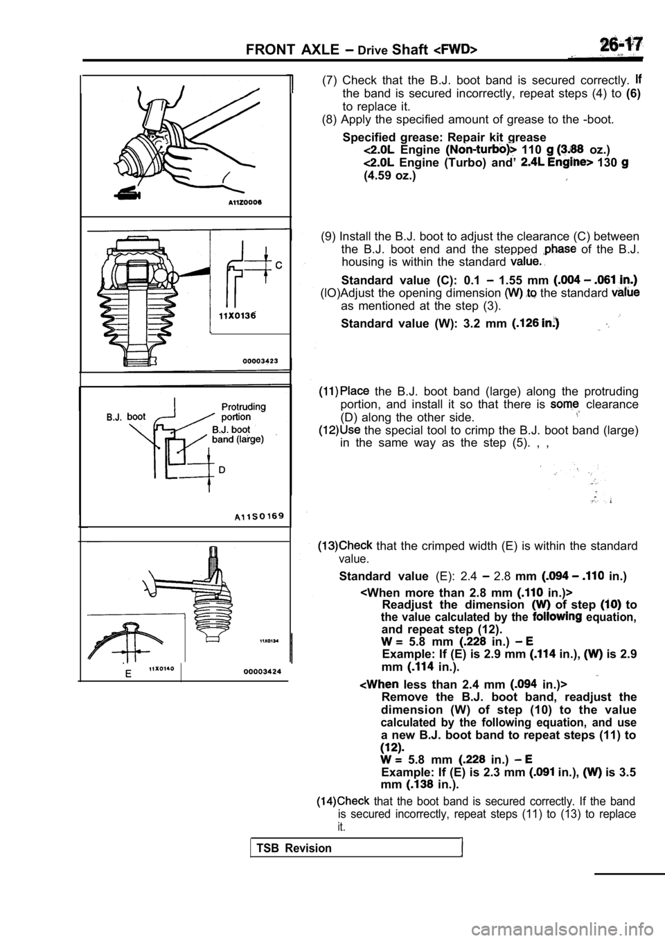
(7) Check that the B.J. boot band is secured correc tly.
the band is secured incorrectly, repeat steps (4) to (6)
to replace it.
(8) Apply the specified amount of grease to the -bo ot.
Specified grease: Repair kit grease
Engine 110 oz.)
Engine (Turbo) and’ 130
(4.59 oz.)
(9) Install the B.J. boot to adjust the clearance ( C) between
the B.J. boot end and the stepped
of the B.J.
housing is within the standard
Standard value (C): 0.1 1.55 mm
(lO)Adjust the opening dimension the standard
as mentioned at the step (3).
Standard value (W): 3.2 mm
the B.J. boot band (large) along the protruding
portion, and install it so that there is
clearance
(D) along the other side.
the special tool to crimp the B.J. boot band (larg e)
in the same way as the step (5). , ,
that the crimped width (E) is within the standard
value.
Standard value (E): 2.4 2.8 mm in.)
Readjust the dimension
of step to
the value calculated by the equation,
and repeat step (12).
5.8 mm in.)
Example: If (E) is 2.9 mm in.), is 2.9
mm
in.).
less than 2.4 mm in.)>
Remove the B.J. boot band, readjust the
dimension (W) of step (10) to the value
calculated by the following equation, and use
a new B.J. boot band to repeat steps (11) to
5.8 mm in.)
Example: If (E) is 2.3 mm in.), is 3.5
mm
in.).
that the boot band is secured correctly. If the ba nd
is secured incorrectly, repeat steps (11) to (13) t o replace
it.
TSB Revision