Page 348 of 2103
11E N G I N E O V E R H A U L Cylinder Head and
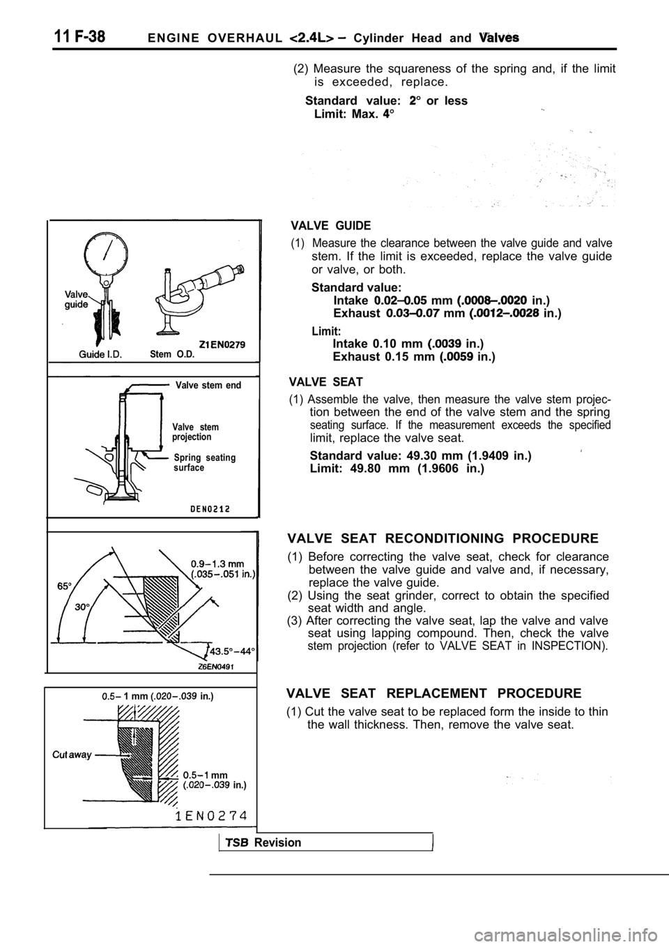
Stem O.D.Valve stem end
Valve stem
projection
Spring seating
surface
1 mm in.)
mm in.)
(2) Measure the squareness of the spring and, if th e limit
is exceeded, replace.
Standard value:
or less
Limit: Max.
VALVE GUIDE
(1)Measure the clearance between the valve guide and v alve
stem. If the limit is exceeded, replace the valve guide
or valve, or both.
Standard value: Intake
mm in.)
Exhaust
mm in.)
Limit:
Intake 0.10 mm in.)
Exhaust 0.15 mm
in.)
VALVE SEAT
(1) Assemble the valve, then measure the valve stem projec-
tion between the end of the valve stem and the spring
seating surface. If the measurement exceeds the spe cified
limit, replace the valve seat.
Standard value: 49.30 mm (1.9409 in.)
Limit: 49.80 mm (1.9606 in.)
VALVE SEAT RECONDITIONING PROCEDURE
(1) Before correcting the valve seat, check for cle arance
between the valve guide and valve and, if necessary ,
replace the valve guide.
(2) Using the seat grinder, correct to obtain the s pecified
seat width and angle.
(3) After correcting the valve seat, lap the valve and valve
seat using lapping compound. Then, check the valve
stem projection (refer to VALVE SEAT in INSPECTION) .
VALVE SEAT REPLACEMENT PROCEDURE
(1) Cut the valve seat to be replaced form the inside to thin
the wall thickness. Then, remove the valve seat.
Revision
Page 349 of 2103
ENGINE OVERHAUL Cylinder Head and Valves
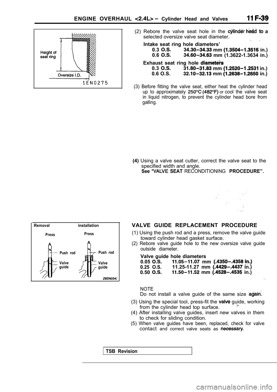
Removalinstallation
Press
A
Press
A
Push rod
Valve
guide Push rod
Valve
guide
(2) Rebore the valve seat hole in the a
selected oversize valve seat diameter.
Intake seat ring hole diameters’
0.3 mm in.)
0.6
mm (1.3622-1.3634 in.)
Exhaust seat ring hole
0.3 mm in.)
0.6 O.S.
mm in.)
(3) Before fitting the valve seat, either heat the cylinder head
up to approximately
or cool the valve seat
in liquid nitrogen, to prevent the cylinder head bo re from
galling.
(4)Using a valve seat cutter, correct the valve seat t o the
specified width and angle.
See SEAT RECONDITIONINGPROCEDURE”.
VALVE GUIDE REPLACEMENT PROCEDURE
(1) Using the push rod and a press, remove the valv e guide
toward cylinder head gasket surface.
(2) Rebore valve guide hole to the new oversize val ve guide
outside diameter.
Valve guide hole diameters
0.05
0.25 O.S.
mm
0.50
11.25-11.27 mm in.)
mm in.)
NOTE
Do not install a valve guide of the same size
(3) Using the special tool, press-fit the guide, working
from the cylinder head top surface.
(4) After installing valve guides, insert new valve s in them
to check for sliding condition.
(5) When valve guides have been, replaced, check fo r valve
contactand correct valve seats as
TSB Revision
Page 365 of 2103
ENGINE OVERHAUL Piston and Rod
INSPECTION
PISTON RING (1) Check the piston ring for
excessive and
breakage and replace if defects. If the’ piston
has been replaced with ,a new one, the piston rings must
also be replaced with, new. ones.
(2) Check for the clearance between the piston ring and
ring groove. If the limit is exceeded, replace the ring
or piston, or both.
Standard value:
mm
Limit: 0.1 mm in.)
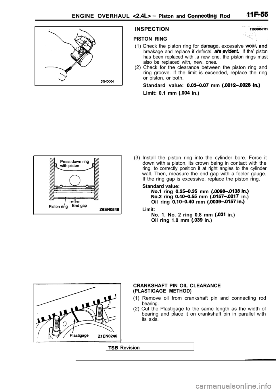
(3) Install the piston ring into the cylinder bore. Force it
down with a piston, its crown being in contact with the
ring, to correctly position it at right angles to the cylinder
wall. Then, measure the end gap with a feeler gauge .
If the ring gap is excessive, replace the piston ri ng.
Standard value:
ring mm
ring mm in.)
Oil ring
mm
Limit:
No. 1, No. 2 ring 0.8 mm in.)
Oil ring 1.0 mm
in.)
Revision
CRANKSHAFT PIN OIL CLEARANCE
(PLASTIGAGE METHOD)
(1) Remove oil from crankshaft pin and connecting r od
bearing.
(2) Cut the Plastigage to the same length as the width of
bearing and place it on crankshaft pin in parallel with
its axis.
Page 366 of 2103
ENGINE OVERHAUL and
(3) Install the connecting rod cap carefully and tighten’
nuts to specified torque.
(4) Carefully remove the
(5) Measure the width of the its widest part
by using a scale printed on the
package.
Standard value:
mm in.)
Limit: 0.1 mm
in.)
TSB Revision
Page 371 of 2103
ENGINE OVERHAUL Crankshaft, Flywheel and, . .
INSPECTION11300880103
CRANKSHAFT OIL CLEARANCE
(1) Remove oil from the crankshaft
bearing.
(2) Install the crankshaft.
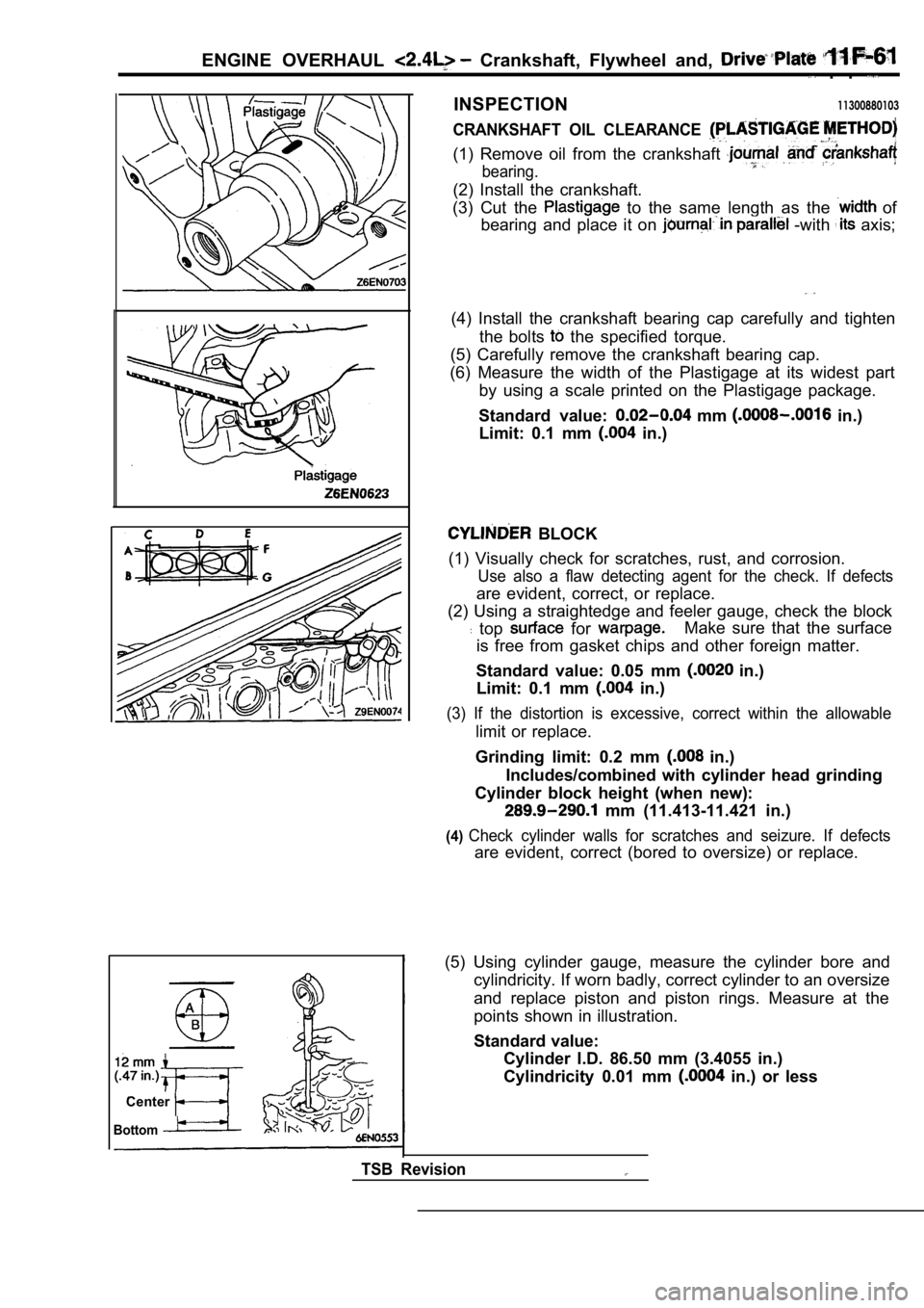
(3) Cut the
to the same length as the of
bearing and place it on
-with axis;
(4) Install the crankshaft bearing cap carefully an d tighten
the bolts
the specified torque.
(5) Carefully remove the crankshaft bearing cap.
(6) Measure the width of the Plastigage at its wide st part
by using a scale printed on the Plastigage package.
Standard value:
mm in.)
Limit: 0.1 mm
in.)
BLOCK
(1) Visually check for scratches, rust, and corrosi on.
Use also a flaw detecting agent for the check. If d efects
are evident, correct, or replace.
(2) Using a straightedge and feeler gauge, check th e block
top for Make sure that the surface
is free from gasket chips and other foreign matter.
Standard value: 0.05 mm
in.)
Limit: 0.1 mm
in.)
(3) If the distortion is excessive, correct within the allowable
limit or replace.
Grinding limit: 0.2 mm
in.)
Includes/combined with cylinder head grinding
Cylinder block height (when new):
mm (11.413-11.421 in.)
(4)Check cylinder walls for scratches and seizure. If defects
are evident, correct (bored to oversize) or replace.
Center
Bottom
TSB Revision
(5) Using cylinder gauge, measure the cylinder bore and
cylindricity. If worn badly, correct cylinder to an oversize
and replace piston and piston rings. Measure at the
points shown in illustration.
Standard value: Cylinder I.D. 86.50 mm (3.4055 in.)
Cylindricity 0.01 mm
in.) or less
Page 416 of 2103
E N G I N E ( N O N - T U R B O ) >
Scan tool 26
Code
No.
scan tool Position Sensor
24
[Comment]
Backgroundl Sensor circuit shorted to
lThe sensor consists of a resistor that provides a signal to the PCMbasedl p o s i t i o n l of on the position of the throffle blade.
l The PCM uses throffle body position information to adjust fuel injector width.,Range of Checkl ignition switch: ON ,Set Conditionl
Throttle position sensor output remains less than for 1 second.
NGCheck the position Replace ,
OK
Measure at the throttle position sensor connector lDisconnect the connector, and measure at the harnes s side.
l between 3 and ground
(ignition switch: ON)
OK: 4.8-5.2
OK
Check connectors:
Check the harness wire and the TPSconnector.Repair, if necessary.
Check the following connectors:
OK
Check trouble symptom.
NG Repair
Check harness wire between the PCM and the TPS connector . Repair
the PCM.
TSB Revision
Page 417 of 2103
![MITSUBISHI SPYDER 1990 Service Repair Manual ENGINE (NON-TURBO)>
Scan tool 27
Code scan tool Throttle Position Sensor Voltage
No. High
24
[Comment] Sensor circuit openBackgroundl position sensor failed
lThe sensor consis MITSUBISHI SPYDER 1990 Service Repair Manual ENGINE (NON-TURBO)>
Scan tool 27
Code scan tool Throttle Position Sensor Voltage
No. High
24
[Comment] Sensor circuit openBackgroundl position sensor failed
lThe sensor consis](/manual-img/19/57345/w960_57345-416.png)
ENGINE (NON-TURBO)>
Scan tool 27
Code scan tool Throttle Position Sensor Voltage
No. High
24
[Comment] Sensor circuit openBackgroundl position sensor failed
lThe sensor consists of a resistor that provides a to the PCM based S e n s o r g r o u n d c i r c u i t on the position of the throttle blade.l The PCM uses throttle body position information to adjust fuel injector width.
Range of Check
l ignition switch: ON
Set Condition
l Throttle position sensor output remains more than for 1 second.
NGCheck the throttle position sensor. (TPS) (Refer to Replace
OK
Measure at the TPS connector lDisconnect the connector, and measure at the harnes s side.
l Continuity between 1 and ground
OK: Continuity
OK
Scan tool 30
Code General scan tool Engine Coolant Temperature
No.Sensor Voltage Too
22
[Comment]l Sensor shorted to Backgroundl Sensor internally shortedlData from the engine temperature sensor is used in most fuel and spark related
l PCM failed
control functions.
Range of Checkl Ignition switch: ON ,
Set ConditionEngine temperature sensor output remains less than 0.51 for 3 seconds.
Check the wire between We PCM and TPS Repair, if necessary.
NG Check the following connectors: Repair ,
Check trouble symptom.
OKNGCheck the harness wire between the PCM and the TPS connector.
NG
Replace
Replace
(Refer to
OK
Repair
OK
Check trouble symptom.
NG N G
the Repair
temperature sensor connector.
OK
Replace the PCM.
TSB Revision
Page 429 of 2103
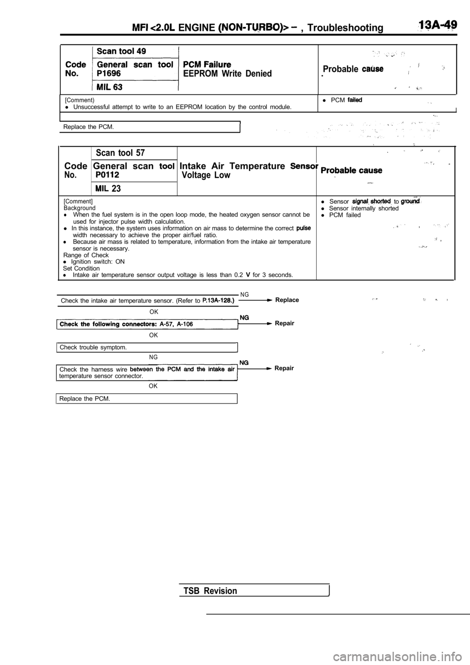
ENGINE , Troubleshooting
EEPROM Write DeniedProbable.
[Comment)l Unsuccessful attempt to write to an EEPROM location by the control module.l
PCMI
Replace the PCM.
Scan tool 57
Code General scan Intake Air Temperature
No.Voltage Low
23
[Comment]l Sensor to Backgroundl Sensor internally shortedlWhen the fuel system is in the open loop mode, the heated oxygen sensor cannot be
l PCM failed
used for injector pulse width calculation.
l In this instance, the system uses information on ai r mass to determine the correct
,
width necessary to achieve the proper air/fuel rati o.lBecause air mass is related to temperature, informa tion from the intake air temperature ,
sensor is necessary.
Range of Check
l Ignition switch: ON
Set Condition
lIntake air temperature sensor output voltage is les s than 0.2 for 3 seconds.
N GCheck the intake air temperature sensor. (Refer to Replace
OK
Repair
OK
Check trouble symptom.
N G
Check the harness wire temperature sensor connector.
OK
Repair
Replace the PCM.
TSB Revision