1990 MITSUBISHI SPYDER width
[x] Cancel search: widthPage 167 of 2103
ENGINE OVERHAUL and
A
INSPECTION
O I L C L E A R A N C E
(1) Remove oil from the crankshaft journal ‘and crankshaft
bearing.
(2) Install the crankshaft.
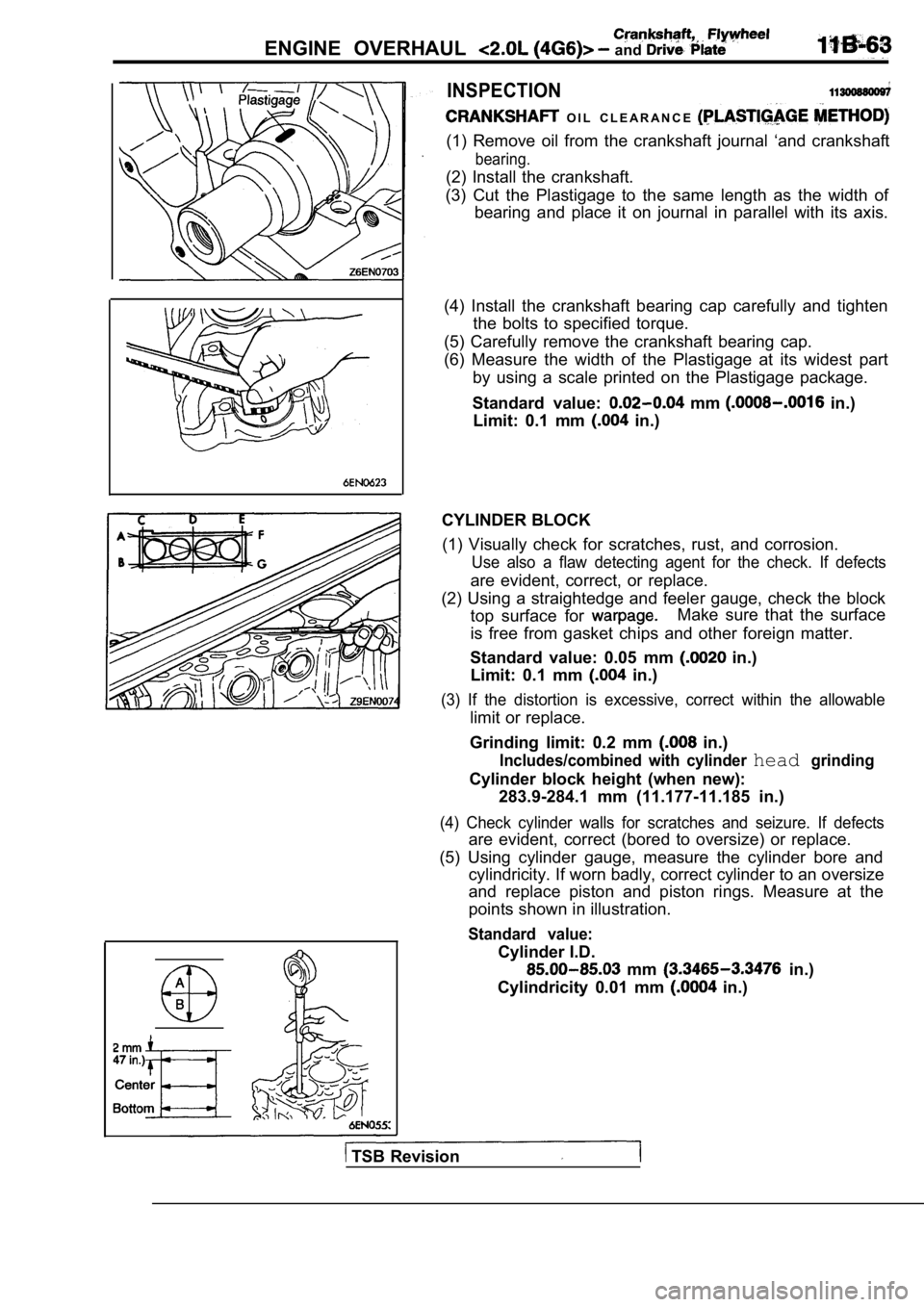
(3) Cut the Plastigage to the same length as the wi dth of
bearing and place it on journal in parallel with it s axis.
(4) Install the crankshaft bearing cap carefully an d tighten
the bolts to specified torque.
(5) Carefully remove the crankshaft bearing cap.
(6) Measure the width of the Plastigage at its wide st part
by using a scale printed on the Plastigage package.
Standard value:
mm in.)
Limit: 0.1 mm
in.)
CYLINDER BLOCK (1) Visually check for scratches, rust, and corrosi on.
Use also a flaw detecting agent for the check. If d efects
are evident, correct, or replace.
(2) Using a straightedge and feeler gauge, check th e block
top surface for
Make sure that the surface
is free from gasket chips and other foreign matter.
Standard value: 0.05 mm
in.)
Limit: 0.1 mm
in.)
(3) If the distortion is excessive, correct within the allowable
limit or replace.
Grinding limit: 0.2 mm
in.)
Includes/combined with cylinder headgrinding
Cylinder block height (when new): 283.9-284.1 mm (11.177-11.185 in.)
(4) Check cylinder walls for scratches and seizure. If defects
are evident, correct (bored to oversize) or replace.
(5) Using cylinder gauge, measure the cylinder bore and
cylindricity. If worn badly, correct cylinder to an oversize
and replace piston and piston rings. Measure at the
points shown in illustration.
Standard value:
Cylinder I.D.
mm in.)
Cylindricity 0.01 mm
in.)
TSB Revision
Page 209 of 2103
ENGINE OVERHAUL
SPECIFICATIONS
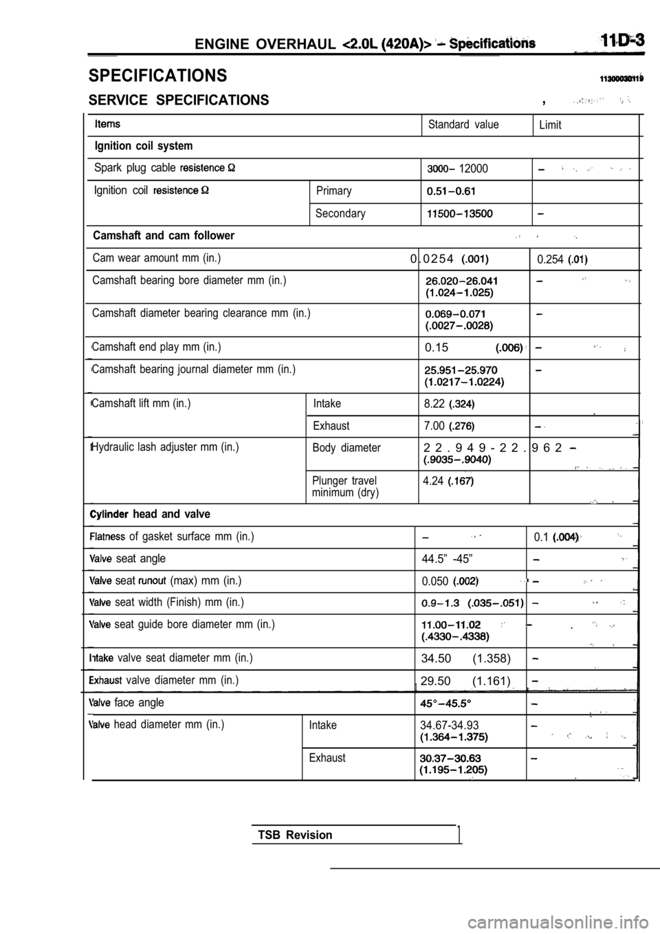
SERVICE SPECIFICATIONS,
Ignition coil system
Standard valueLimit
Spark plug cable
Ignition coil
Camshaft and cam follower
Cam wear amount mm (in.)
Camshaft bearing bore diameter mm (in.) Primary
Secondary
12000
0 . 0 2 5 40.254
Camshaft diameter bearing clearance mm (in.)
Camshaft end play mm (in.)
Camshaft bearing journal diameter mm (in.)
0.15
Camshaft lift mm (in.)
Hydraulic lash adjuster mm (in.)
head and valve
Intake
Exhaust
Body diameter
Plunger travel
minimum (dry)8.22.
7.00
2 2 . 9 4 9 - 2 2 . 9 6 2
4.24
of gasket surface mm (in.)
seat angle
seat (max) mm (in.)
seat width (Finish) mm (in.)
seat guide bore diameter mm (in.)
valve seat diameter mm (in.)
valve diameter mm (in.)
face angle
head diameter mm (in.) Intake
Exhaust
0.1
44.5” -45”
0.050
.
34.50 (1.358)
29.50 (1.161)
34.67-34.93
TSB Revision1
Page 211 of 2103
ENGINE OVERHAUL Specifications
Items
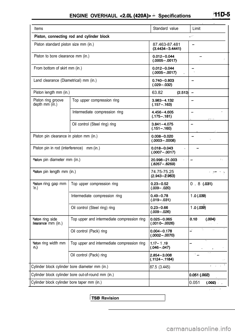
Piston, connecting rod and cylinder block
Piston standard piston size mm (in.)
Standard valueLimit
,
87.463-87.481
Piston to bore clearance mm (in.)
From bottom of skirt mm (in.)
.
Land clearance (Diametrical) mm (in.)
Piston length mm (in.)
Piston ring groove Top upper compression ring
depth mm (in.)
Intermediate compression ring
Oil control (Steel ring) ring
Piston pin clearance in piston mm (in.)
Piston pin in rod (interference) mm (in.)
63.82
.
,
,
pin diameter mm (in.)
pin length mm (in.)74.75-75.25
ring gap mmTop upper compression ring0 . 8
‘in.)
Intermediate compression ring1
Oil control (Steel ring) ring1
ring sideTop upper and intermediate compression ring
mm (in.)
Oil control (Pack) ring
ring width mmTop upper and intermediate compression ring 1
. ,
Oil control (Pack) ring
Cylinder block cylinder bore diameter mm (in.)
Cylinder block cylinder bore out-of-round mm (in.)
Cylinder block cylinder bore taper mm (in.) 87.5 (3.445)
0.051 .
Revision
Page 214 of 2103
ENGINE OVERHAUL
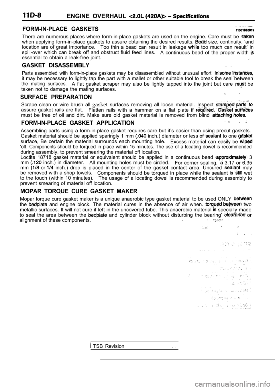
FORM-IN-PLACE GASKETS
There are numerous places where form-in-place gaskets are used on the engine. Care must be
when applying form-in-place gaskets to assure obtaining the desired results. size, continuity, ‘and
location are of great importance. Too thin a bead can result in leakage
too much can result’ in
spill-over which can break off and obstruct fluid f eed lines.
A continuous bead of the proper width
essential to obtain a leak-free joint.
GASKET DISASSEMBLY
Parts assembled with form-in-place gaskets may be d isassembled without unusual effort’
it may be necessary to lightly tap the part with a mallet or other suitable tool to break the seal between
the mating surfaces.A flat gasket scraper may also be lightly tapped in to the joint but care be
taken not to damage the mating surfaces.
SURFACE PREPARATION
Scrape clean or wire brush all gasketsurfaces removing all loose material. Inspect
assure gasket rails are flat.
Flatten rails with a hammer on a flat plate if
must be free of oil and dirt. Make sure old gasket material is removed from blind
FORM-IN-PLACE GASKET APPLICATION
Assembling parts using a form-in-place gasket requires care but it’s easier than using precut gaskets.
Gasket material should be applied sparingly 1 mm
inch.) diameter or less to one
surface, Be certain the material surrounds each mou nting hole.
Excess material can easily be
‘off. Components should be torqued in place within 15 minutes. The use of a locating dowel is recommen ded
during assembly, to prevent smearing the material off location.
Loctite 18718 gasket material or equivalent should be applied in a continuous bead
3
mm
inch.) in diameter. All mounting holes must be circled.
For corner sealing, 3.17 or 6.35
mm
or inch.) drop is placed in the center of the gasket contact area. Uncured may
be removed with a shop towels. Components should be torqued in place while the sea lant
wet
to the touch (within 10 minutes). The usage of a locating dowel is recommended during assembly to
prevent smearing of material off location.
MOPAR TORQUE CURE GASKET MAKER
Mopar torque cure gasket maker is a unique anaerobi c type gasket material to be used ONLY
the and engine block. The material cures in the absenc e of air when. two
metallic surfaces. It will not cure if left in the uncovered tube. This anaerobic material
specially made
to seal the area between the
and cylinder block without disturbing the bearing’ or
alignment of these components.. .
TSB Revision
Page 243 of 2103
(Overall)
Intake 111.49-111.99 mm (4.389-4.499 in.) Exhaust
mm in.)
Stem Diameter
Intake 5.934-5.952 mm in.)
Exhaust
mm in.)
Valve Margin
Intake 1.285-1.615 mm in.)
Exhaust
mm in.)
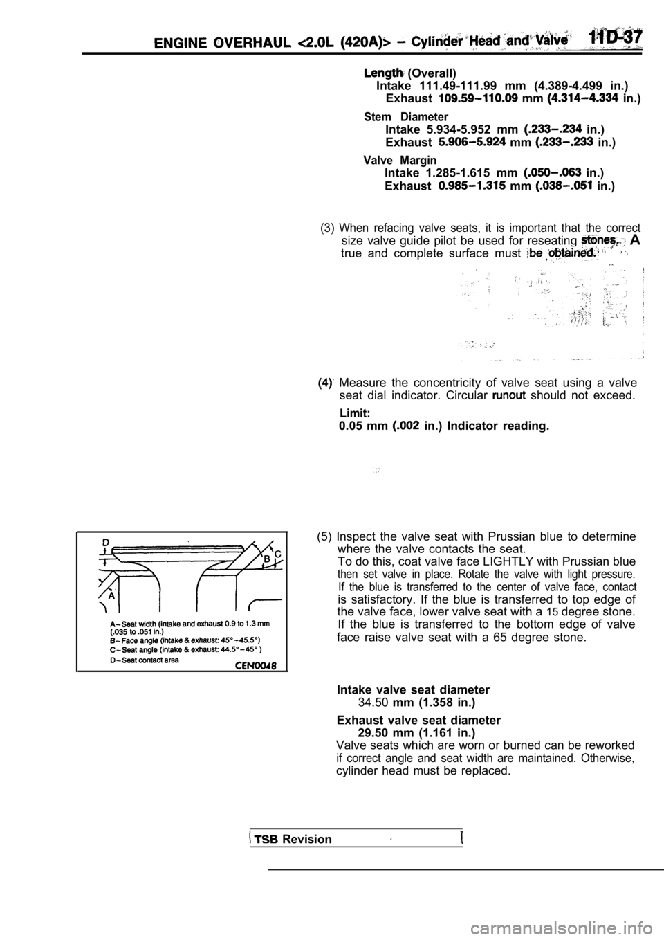
(3) When refacing valve seats, it is important that the correct
size valve guide pilot be used for reseating A
true and complete surface must
Measure the concentricity of valve seat using a va lve
seat dial indicator. Circular
should not exceed.
Limit:
0.05 mm in.) Indicator reading.
(5) Inspect the valve seat with Prussian blue to de termine
where the valve contacts the seat.
To do this, coat valve face LIGHTLY with Prussian b lue
then set valve in place. Rotate the valve with light pressure.
If the blue is transferred to the center of valve f ace, contact
is satisfactory. If the blue is transferred to top edge of
the valve face, lower valve seat with a 15degree stone.
If the blue is transferred to the bottom edge of va lve
face raise valve seat with a 65 degree stone.
Intake valve seat diameter 34.50 mm (1.358 in.)
Exhaust valve seat diameter 29.50 mm (1.161 in.)
Valve seats which are worn or burned can be reworke d
if correct angle and seat width are maintained. Otherwise,
cylinder head must be replaced.
Revision
Page 244 of 2103
11ENGINE OVERHAUL Cylinder Head
(6) seat is properly positioned, the width of intake
and exhaust seats should be 0.9 to 1.3 mm
to
in.).
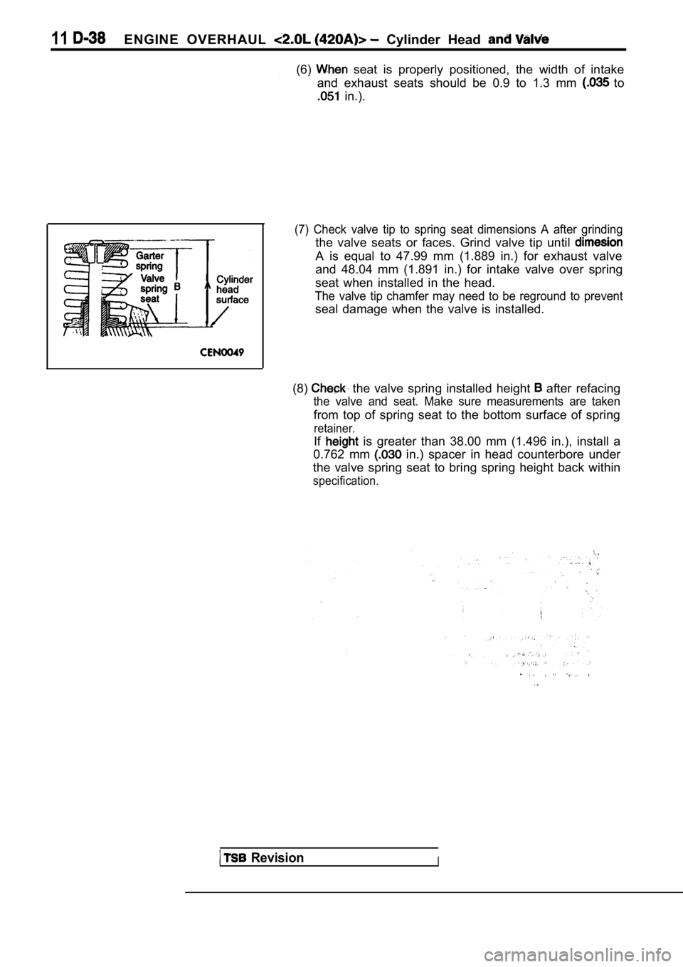
(7) Check valve tip to spring seat dimensions A aft er grinding
the valve seats or faces. Grind valve tip until
A is equal to 47.99 mm (1.889 in.) for exhaust valv e
and 48.04 mm (1.891 in.) for intake valve over spri ng
seat when installed in the head.
The valve tip chamfer may need to be reground to pr event
seal damage when the valve is installed.
(8)
the valve spring installed height after refacing
the valve and seat. Make sure measurements are take n
from top of spring seat to the bottom surface of spring
retainer.
If is greater than 38.00 mm (1.496 in.), install a
0.762 mm
in.) spacer in head counterbore under
the valve spring seat to bring spring height back w ithin
specification.
RevisionI
Page 260 of 2103
piston,
ENGINE OVERHAUL Cylinder Block
CONNECTING BEARING
(1) Place a piece of Plastigage across the, width of
bearing in the cap 6.35
mm off center and away -from the hole.
suspect areas can be checked, by placing in
the suspect area.
(2) Before assembling the rod with in place;
‘the crankshaft must be rotated the connecting rod
being checked starts moving toward the top of the e ngine.,
Only then should the cap be and torqued
to the specification.
Do not rotate the crankshaft while assembling the cap
or the Plastigage may be smeared, giving inaccurate re-
sults.
(3) Remove the bearing cap and compare the width of the
flattened Plastigage with the metric scale provided on
the package.
Standard value: mm in.)
Limit: 0.075 mm
in.)
bolt
Threads are not straight on line
Threads are straight
line,
bolt
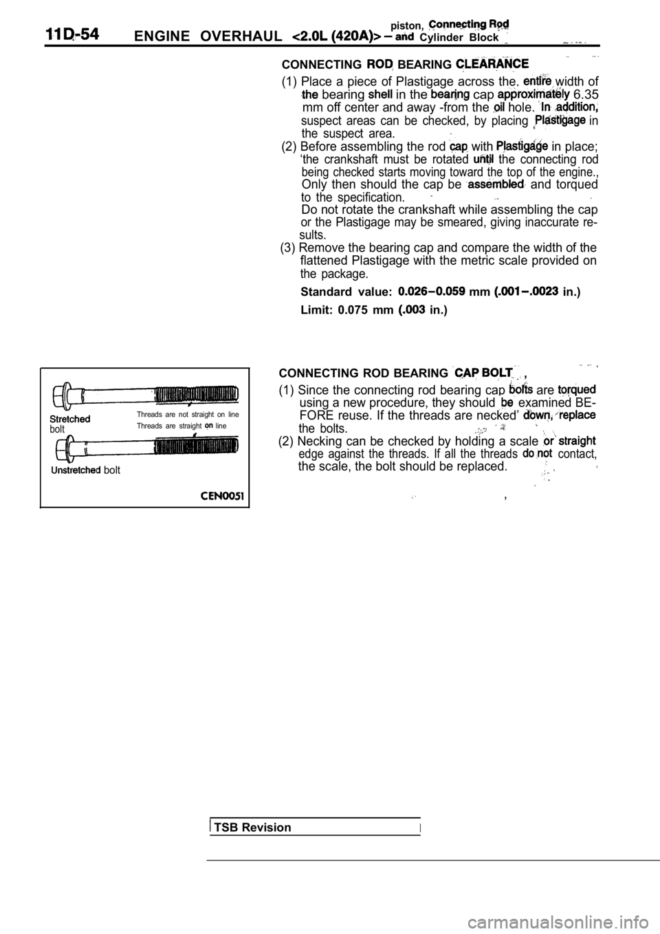
CONNECTING ROD BEARING ,
(1) Since the connecting rod bearing cap are
using a new procedure, they should examined BE-
FORE reuse. If the threads are necked’
the bolts.
(2) Necking can be checked by holding a scale
edge against the threads. If all the threads contact,
the scale, the bolt should be replaced. .
,
TSB RevisionI
Page 267 of 2103
ENGINE
BEARING CLEARANCE
(1) The. total: clearance of the main bearings can only be
determined by removing the weight of the crankshaft .
This is accomplished by having the engine turned upside
down on the engine stand. This will remove all the crank-
weight off the bearing surface.
(2) Place, a piece of Plastigage across the entire width of
the bearing shell in the approximately 6.35 mm
in.) off center and away from the oil holes. In addition,
suspect areas can be checked by placing the Plastig age
in the suspect area.
Torque the
bolts of the bearing being checked
to the proper specifications.
Caution
Do not rotate crankshaft, or the Plastigage may be
smeared.
(3) Remove the and compare the width of the flat-
tened Plastigage with the metric scale provided on the
package.
Standard value: mm in.)
Stretched
boltThreads are straight on line,
Unstretched bolt
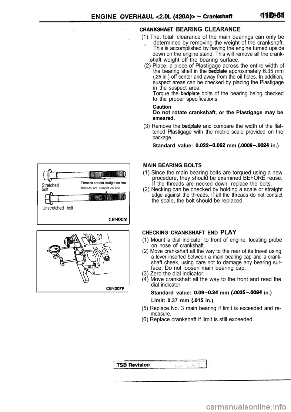
MAIN BEARING BOLTS
(1) Since the main bearing bolts are torqued using a new
procedure, they should be examined BEFORE reuse.
If the threads are necked down, replace the bolts.
(2) Necking can be checked by holding a scale or st raight
edge against the threads. If all the threads do not contact
the scale, the bolt should be replaced.
CHECKING CRANKSHAFT END PLAY
(1) Mount a dial indicator to front of engine, locating probe
on nose of crankshaft.
(2) Move crankshaft all the way to the rear of its travel using
a lever inserted between a main bearing cap and a c rank-
shaft cheek, using care not to damage any bearing sur-
face, Do not loosen main bearing cap.
(3) Zero the dial indicator.
(4) Move crankshaft all the way to the front and re ad the
dial indicator.
Standard value: mm in.)
Limit: 0.37 mm
in.)
(5) Replace No. 3 main bearing if limit is exceeded and re-
measure.
(6) Replace crankshaft if limit is still exceeded.