Page 44 of 2103
GENERALMaintenanceService
Drain
Oil pan side
Engine
Engine (Turbo) and
TSB Revision
Engine (Non-turbo)>
1. Pull orpush at the mid point of the belt with aforce
of 98
(22 Ibs.) to measure dirve belt deflection.
Standard value:
mm in.)
2. Use a tension gauge to measure belt
Standard value:
9. ENGINE OIL (Change)
Use the specified oil. (Refer to
Caution
Never use nondetergent or straight mineral oil.
1. After warming up the engine, remove the oil fill er cap.
2.Remove the drain plug to allow the engine oil to drain.
3.Replace the drain plug gasket with a new one and ti ghten,
the drain plug.
4. Supply new engine oil through the oil filler.
Engine oil total quantity:[including oil filter and oil cooler]
Enine (Non-turbo) and
4.3 dm(4 qts.)
Enine (Turbo)>’
4.4 dm (4.6 qts.)
Start and run the engine a few
Stop the engine and check the level is within
the level range indicated on the oil dipstick.
5.
6.
Page 48 of 2103

GENERAL Maintenance
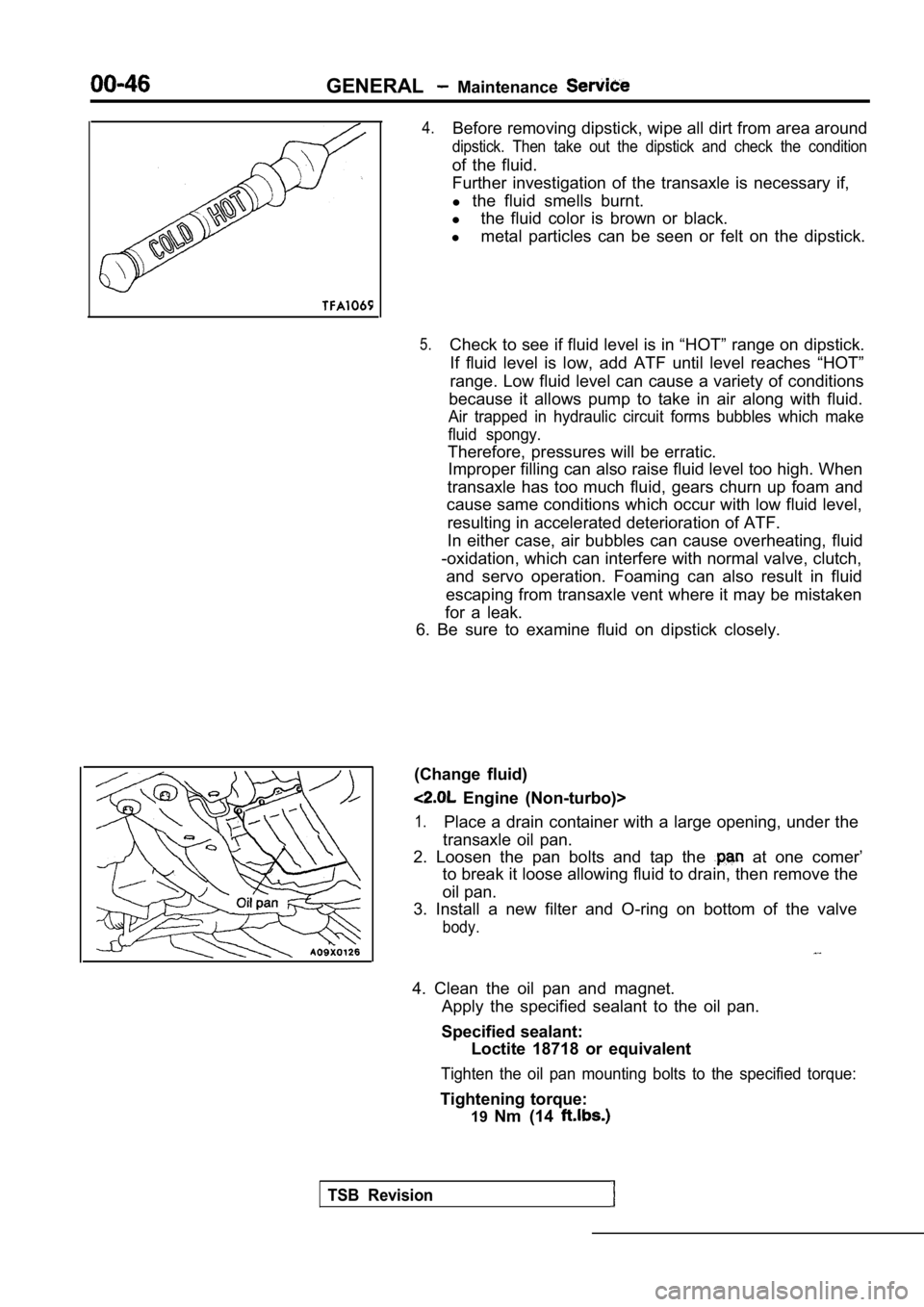
4.Before removing dipstick, wipe all dirt from area around
dipstick. Then take out the dipstick and check the condition
of the fluid.
Further investigation of the transaxle is necessary if,
l the fluid smells burnt.
l the fluid color is brown or black.
l metal particles can be seen or felt on the dipstick .
5.Check to see if fluid level is in “HOT” range on dipstick.
If fluid level is low, add ATF until level reaches “HOT”
range. Low fluid level can cause a variety of condi tions
because it allows pump to take in air along with fl uid.
Air trapped in hydraulic circuit forms bubbles which make
fluid spongy.
Therefore, pressures will be erratic. Improper filling can also raise fluid level too hig h. When
transaxle has too much fluid, gears churn up foam a nd
cause same conditions which occur with low fluid le vel,
resulting in accelerated deterioration of ATF.
In either case, air bubbles can cause overheating, fluid
-oxidation, which can interfere with normal valve, clutch,
and servo operation. Foaming can also result in flu id
escaping from transaxle vent where it may be mistak en
for a leak.
6. Be sure to examine fluid on dipstick closely.
(Change fluid)
Engine (Non-turbo)>
1.Place a drain container with a large opening, under the
transaxle oil pan.
2. Loosen the pan bolts and tap the
at one comer’
to break it loose allowing fluid to drain, then rem ove the
oil pan.
3. Install a new filter and O-ring on bottom of the valve
body.
4. Clean the oil pan and magnet.
Apply the specified sealant to the oil pan.
Specified sealant: Loctite 18718 or equivalent
Tighten the oil pan mounting bolts to the specified torque:
Tightening torque:
19Nm (14
TSB Revision
Page 49 of 2103

GENERALMaintenance Service
5.Add 3.8 (4.0 qts.) of the specified transmission fluid
through the filler tube.
Specified fluid:DIAMOND ATF SP IIor equivalent
6. Start the engine and allow it to run at idle for at least
one minute. Then, with parking and service brake ap plied,
move the selector lever momentarily to each positio n,
ending in the park or neutral position.
7.Add sufficient fluid to bring to’ inch below the
ADD mark.
8.Recheck fluid level after is normal operating
temperature. The level should be in the HOT region.
Engine (Turbo) and Engine>
Drain the fluid and check whether there is any evid ence of
contamination.
Refill with new fluid after the cause of any contam ination
has been corrected.
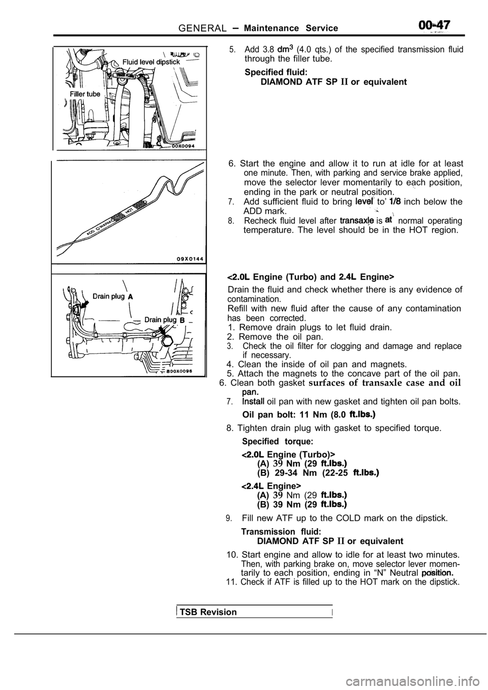
1. Remove drain plugs to let fluid drain.
2. Remove the oil pan.
3.Check the oil filter for clogging and damage and re place
if necessary.
4. Clean the inside of oil pan and magnets.
5. Attach the magnets to the concave part of the oi l pan.
6. Clean both gasket surfaces of transaxle case and oil
7. oil pan with new gasket and tighten oil pan bolts.
Oil pan bolt: 11 Nm (8.0
8. Tighten drain plug with gasket to specified torq ue.
Specified torque:
Engine (Turbo)>
(A) 39Nm (29
(B) 29-34 Nm (22-25
Engine>
(A) 39Nm (29
(B) 39 Nm (29
9.Fill new ATF up to the COLD mark on the dipstick.
Transmission fluid:
DIAMOND ATF SP IIor equivalent
10. Start engine and allow to idle for at least two minutes.
Then, with parking brake on, move selector lever mo men-
tarily to each position, ending in “N” Neutral
11. Check if ATF is filled up to the HOT mark on the dipstick.
TSB RevisionI
Page 133 of 2103
ENGINE OVERHAUL Exhaust Manifold
EXHAUST MANIFOLD AND WATER PUMP
REMOVAL AND INSTALLATION
11300490108
. .
10
Nm
120
2I
27
14 29
21
14 Nmin
Nm
I 7
I - Nm
13 Nm
‘ - 2 3
Nm
10
Nm32
Removal steps
1.Oil dipstick17.Water pipe 2.Oil dipstick guide18.Turbocharger3.O-ring19.Engine hanger4.Heat protector “A”20.Exhaust manifold5.Heat protector 21.Gasket6.Heated oxygen sensor22.Water hose7.Exhaust fitting23.Water pipe 8.Gasket24.Water pipe9.Oil pipe “A”25. Water hose10.Oil pipe 26.Water hose11.Oil return pipe27. Water hose12.Gasket28.Water hose13.Turbocharger assembly29. O-ring14.Gasket30.Water inlet pipe15.Ring31.Water pump16.Water pipe “A”32.Gasket
TSB Revision
Page 261 of 2103
OVERHAUL
CRANKSHAFT
REMOVAL
Procedures after removing crankshaft sprocket, oil pan, pis-
tons and connecting rods.
(1) Using Tool remove front crankshaft oil seal.
Be careful not to damage the seal surface of cover.
(2) out rear seal with screwdriver. Becareful not to nick
or damage crankshaft flange seal surface or retaine r bore.
(3) Remove main bearing cap
(4) Remove bearing lower.
(5) Remove crankshaft.
(6) Remove bearing upper.
(7) Remove knock sensor.
(8) Remove oil pressure switch.
(9) Remove oil level gauge (dipstick).
Revision
Page 262 of 2103
ENGINE Crankshaft
Oil holes
I N S T A L L A T I O N
(1) Install oil level gauge (dipstick).
(2) Install oil pressure switch.
,
,
(3) Install knock sensor. Tighten knock sensor to 10 Nm
(7 torque. Over or under tightening effects knock
sensor performance, possibly causing improper spark con-
t r o l .
(4) Select proper thickness main bearing shells by referring
to CRANKSHAFT BEARING CLEARANCE.
NOTE
Upper and lower No. 3 bearing halves are flanged to
carry the crankshaft thrust loads and are NOT inter change-
able with any other bearing halves in the engine. Bearing
shells are available in standard and the following under-
sized:
0.016 mm, 0.032 mm, 0.250 mm.
Never install an undersize bearing that will reduce clear-
ance below specifications.
(5) Install the main bearing shells with the lubric ation groove
in the cylinder block.
TSB Revision
Page 375 of 2103
ENGINE LUBRICATION Service
DraingasketOil pan side
Engine (Non-turbo)>
If these oils are not available, an API classificat
ion
or can be used.’ . .
ON-VEHICLE
ENGINE OIL
.
Pull out the oil dipstick slowly and check that the oil
is within the marks on the oil dipstick.
2.Check that the oil is dirty, that there is
no coolant or gasoline mixed in, ‘and that it has, sufficient
viscosity.
ENGINE OIL REPLACEMENT
After warming up the engine, remove the oil filler cap.
2.Remove the drain plug to allow the engine oil to drain.
3.Replace the drain plug gasket with a new one and ti ghten
the drain plug.
Page 376 of 2103
![MITSUBISHI SPYDER 1990 Service Repair Manual 12-4 L U B R I C A T I O N
EngineI
Turbo
4. Supply new engine oil through the oil filler.Engine oil total quantity:[including oil filter and oil cooler]
Engine (Non-turbo) arid MITSUBISHI SPYDER 1990 Service Repair Manual 12-4 L U B R I C A T I O N
EngineI
Turbo
4. Supply new engine oil through the oil filler.Engine oil total quantity:[including oil filter and oil cooler]
Engine (Non-turbo) arid](/manual-img/19/57345/w960_57345-375.png)
12-4 L U B R I C A T I O N
EngineI
Turbo
4. Supply new engine oil through the oil filler.Engine oil total quantity:[including oil filter and oil cooler]
Engine (Non-turbo) arid
4 . 3 (4 q t s . )
Engine (Turbo)>
4.4
(4.6 qts.)
5. Start and run the engine a
minutes.
6.Stop the engine and check the engine oil level is w ithin
the level range indicated on the oil dipstick.
.
NOTE
may be used for operation in very cold weather
areas where the lowest ambient temperature is below
OIL REPLACEMENT
1. Remove the engine oil filler cap.
2.Remove the engine oil drain plug, and drain out the engine
o i l .
3.Remove the engine oil filter by using the oil filter wrench.
4.Clean the oil filter mounting, surface of the oil f ilter bracket.
5. Coat engine oil to the O-ring of’new filter: .
6.Screw on the oil filter by hand until it touchesthe surface
of the flange and then tighten it with. the filter wrench:
etc.
Engine (Turbo) Engine>
lFor One full turn or 14 Nm
lFor or 17 Nm (12
E n g i n e ( N o n - t u r b o ) >
lFor 090: turn or 21 Nm (15
7. Add new engine oil through the oil filter.
8. Start and run engine and check for engine oil le aks.
9. After stopping engine, check oil level and reple nish as
necessary.
TSB Revision