1990 MITSUBISHI SPYDER catalytic converter
[x] Cancel search: catalytic converterPage 35 of 2103

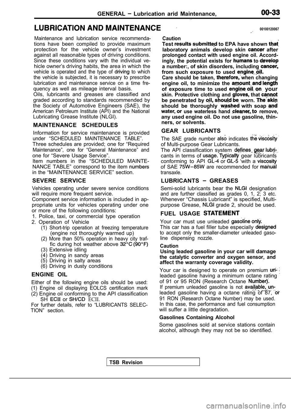
GENERAL Lubrication arid Maintenance,
00100120067
Maintenance and lubrication service recommenda-
tions have been compiled to provide maximum
protection for the vehicle owner’s investment
against all reasonable types of driving conditions.
Since these conditions vary with the individual ve-
hicle owner’s driving habits, the area in which the
vehicle is operated and the type of to which
the vehicle is subjected, it is necessary to prescr ibe
lubrication and maintenance service on a time fre-
quency as well as mileage interval basis.
Oils, lubricants and greases are classified and
graded according to standards recommended by
the Society of Automotive Engineers (SAE), the
American Petroleum Institute (API) and the National
Lubricating Grease Institute (NLGI).
MAINTENANCE SCHEDULES
Information for service maintenance is provided
under “SCHEDULED MAINTENANCE TABLE”.
Three schedules are provided; one for “Required
Maintenance”, one for “General Maintenance” and
one for “Severe Usage Service”. Item numbers in the “SCHEDULED MAINTE-
NANCE TABLE” correspond to the item
in the “MAINTENANCE SERVICE” section.
SEVERE SERVICE
Vehicles operating under severe service conditions
will require more frequent service. Component service information is included in ap-
propriate units for vehicles operating under one
or more of the following conditions:
1. Police, taxi, or commercial type operation
2. Operation of Vehicle
(1) Short-trip operation at freezing temperature
(engine not thoroughly warmed up)
(2) More than 50% operation in heavy city traf-
fic during hot weather above
(3) Extensive idling
(4) Driving in sandy areas
(5) Driving in salty areas
(6) Driving in dusty conditions
ENGINE OIL
Either of the following engine oils should be used:
(1) Engine oil displaying EOLCS certification mark
(2) Engine oil conforming to the API classification SH
or ECII.
For further details, refer to “LUBRICANTS SELEC-
TION” section.
Caution
Test to EPA have shown
laboratory animals develop skin after
prolonged contact with used engine oil. Accord-
ingly, the potential exists for
to
a number:, of skin disorders, including
from such exposure to used
Care should be taken, when changing
engine oil, to minimize the
of exposure time to used your
skin. Protective clothing and that
be penetrated by worn.
should be thoroughly with soap
use waterless hand remove,
any used engine oil. Do not use gasoline, thin- ners, or solvents.
GEAR LUBRICANTS
The SAE grade number indicates
of Multi-purpose Gear Lubricants.
The API classification system
cants in terms of gear lubricants
conforming to API
or ‘with a
of SAE are recommended for
transaxle.
LUBRICANTS GREASES
Semi-solid lubricants bear the
designation
and are further classified as grades 0, 1, 2; 3 etc .
Whenever “Chassis Lubricant” is specified, Multi-
purpose Grease,
grade 2, should be used.
FUEL USAGE
Your car must use unleaded
This car has a fuel filler tube especially
to accept only the smaller-diameter unleaded gaso- line dispensing nozzle.
Caution
Using leaded gasoline in your car will damage
the catalytic converter and oxygen sensor, and
affect the warranty coverage validity.
Your car is designed to operate on premium
leaded gasoline having a minimum octane rating
of 91 or 95 RON (Research Octane
If premium unleaded gasoline is not
leaded gasoline having a octane rating of 87,
91 RON (Research Octane Number) may be used. In this case, the performance and fuel consumption
will suffer a little degradation.
Gasolines Containing Alcohol
Some gasolines sold at service stations contain
alcohol, although they may not be so identified.
TSB Revision
Page 401 of 2103

ENGINE (NON-TURBO)>
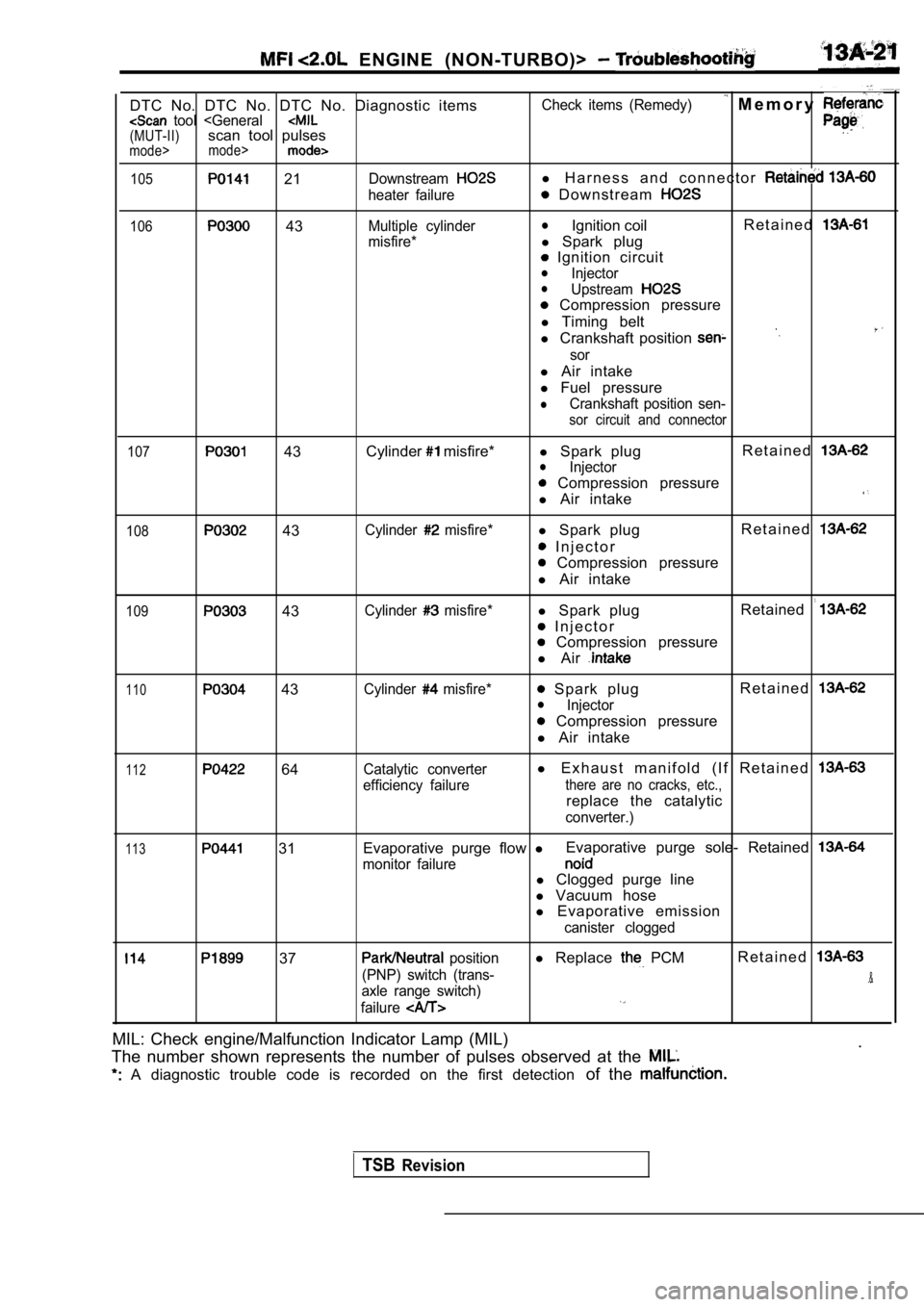
DTC No. DTC No. DTC No. Diagnostic items tool
105 21Downstream
heater failure
106 43Multiple cylinder
misfire* Check items (Remedy)
M e m o r y
l
H a r n e s s a n d c o n n e c t o r
D o w n s t r e a m
lIgnition coil R e t a i n e d
l
Spark plug
Ignition circuitlInjectorlUpstream
Compression pressure
l Timing belt
l Crankshaft position
sor
l Air intake
l Fuel pressure
lCrankshaft position sen-
sor circuit and connector
107
43 Cylinder misfire*
l Spark plug R e t a i n e dlInjector
Compression pressure
l Air intake
108 43Cylinder misfire*l Spark plug R e t a i n e d
I n j e c t o r
Compression pressure
l Air intake
109 43Cylinder misfire*l Spark plug Retained
I n j e c t o r
Compression pressure
l Air
110 43Cylinder misfire* Spark plug R e t a i n e dlInjector
Compression pressure
l Air intake
112 64Catalytic converter
efficiency failurel E x h a u s t m a n i f o l d ( I f R e t a i n e d
there are no cracks, etc.,
replace the catalytic
converter.)
113 31 Evaporative purge flow
lEvaporative purge sole- Retained
monitor failurel
Clogged purge line
l Vacuum hose
l Evaporative emission
canister clogged
37 position
(PNP) switch (trans-
axle range switch)
failurel Replace PCMR e t a i n e d
.&
MIL: Check engine/Malfunction Indicator Lamp (MIL)
.
The number shown represents the number of pulses ob served at the
A diagnostic trouble code is recorded on the first detection of the
TSBRevision
Page 441 of 2103
![MITSUBISHI SPYDER 1990 Service Repair Manual ENGINE (NON-TURBO)>
Scan tool 106
Code General scan tool
No.Multiple Cylinder Mlsfire
43
[Comment]Background
l Excessive engine misfire results in increased catal yst temperature. MITSUBISHI SPYDER 1990 Service Repair Manual ENGINE (NON-TURBO)>
Scan tool 106
Code General scan tool
No.Multiple Cylinder Mlsfire
43
[Comment]Background
l Excessive engine misfire results in increased catal yst temperature.](/manual-img/19/57345/w960_57345-440.png)
ENGINE (NON-TURBO)>
Scan tool 106
Code General scan tool
No.Multiple Cylinder Mlsfire
43
[Comment]Background
l Excessive engine misfire results in increased catal yst temperature.
l Severe misfire could cause catalyst damage.
l To prevent catalytic converter damage, the PCM moni tors engine misfire.
l The PCM monitors for misfire during most engine ope rating conditions.
lWhen a misfire is detected, the PCM stores a diagnostic trouble code and causes the to either flash or illuminate continuously during active misfire.
Range of Check
l MAP voltage is less than 1.60
l Engine speed is between 2200 and 2800 l Engine coolant temperature is greater than l Vehicle speed less than Set Condition
l 1000 Rev Misfire
The PCM detects misfire in more than 1.6% of the en gine cycles in a 1000 revolution
period.l 200 Rev MisfireThe PCM detects misfire in more than 15% of the eng ine cycles in a 200 revolution period.
.
Spark plugs or wires failed
l Ignition coil failed
l Crankshaft position piston rings v a l v e s
l Head gasket failed
l C r a c k e d
l Fuel lines and filter failed
l Fuel failed
l failed
l Wiring and connectors failed
l Engine coolant
l Timing belt tooth broken,
l EGR
SCAN TOOL SENSOR READ TESTS (Data list)
05 Engine coolant temperature sensor (Refer to Check the engine coolant temperature circuit.
(Refer to INSPECTION PROCEDURE 38.)
OK
SCAN TOOL SENSOR READ TESTS (Data list)
27 Intake air temperature sensor (Refer to
OK
Check the intake air temperaturecircuit.(Refer to INSPECTION PROCEDURE
SCAN TOOL SENSOR READ TESTS (Data list)
11 MAP sensor reading (Refer to
OK
OK
Check the MAP sensor circuit.(Refer to INSPECTION PROCEDURE 40.)
SCAN TOOL SENSOR READ TESTS (Data list)
Check the following connectors: 66 Oxygen sensor volts (front) (Refer to OK: Repeat and alternately whenidling.
Check the fuel pressure. (Refer to Check the harness wire between the PCM and the cran kshaft
position sensor connector.
l Check the injectors for operation sound.
l Check the injectors for fuel leakage.
l Check the evaporative emission control system.
Check the following items.
l Check the ignition coil, spark plug cables.
l Check the compression pressure.
Check the EGR
TSB Revision
Page 442 of 2103
![MITSUBISHI SPYDER 1990 Service Repair Manual E N G I N E
Scan tool
Cylinder Misfire
Code General scan tool Cylinder Misfire
No.Cylinder MisfireProbable cause
Cylinder Misfire
43,
[Comment]
Backgroundl Spark plugs or ,
l Exc MITSUBISHI SPYDER 1990 Service Repair Manual E N G I N E
Scan tool
Cylinder Misfire
Code General scan tool Cylinder Misfire
No.Cylinder MisfireProbable cause
Cylinder Misfire
43,
[Comment]
Backgroundl Spark plugs or ,
l Exc](/manual-img/19/57345/w960_57345-441.png)
E N G I N E
Scan tool
Cylinder Misfire
Code General scan tool Cylinder Misfire
No.Cylinder MisfireProbable cause
Cylinder Misfire
43,
[Comment]
Backgroundl Spark plugs or ,
l Excessive engine misfire results in increased catal yst temperature.l l . valves
l Severe misfire could cause catalyst damage.
l To prevent catalytic converter damage, the PCM moni tors engine’ misfire.l
H e a d g a s k e t f a i l e d
l The PCM monitors for misfire during most engine ope rating conditions., h e a d
When a misfire is detected, the PCM stores a diagno
stic trouble code and causes thel
Injector failedl to either flash or illuminate continuously during active misfire.
Range of Check
l MAP voltage is less than
l Engine speed is between 2200 and l Engine coolant temperature is greater than l Vehicle speed less than Set Conditionl 1000 Rev Misfire l
Wiring harness and connectors failed
6
The PCM detects misfire in more than 1.6% of the en gine cycles in a 1000 revolutionperiod. 200 Rev MisfireThe PCM detects misfire in more than 15% of the eng ine cycles in a revolution period.
NG
OK
OK
TSB Revision
Check the following items.
l Check the spark plug, spark plug cables.
l Check compression pressure.
l Check the cylinder head gasket and intake manifold gasket for damage.
Page 443 of 2103
![MITSUBISHI SPYDER 1990 Service Repair Manual ENGINE (NON-TURBO)>
Scan tool 112
C o d e G e n e r a l s c a n t o o l C a t a l y t i c C o n v e r t e r E f f i c i e nc y
No.Failure,
64
[Comment]l Catalytic converter Back MITSUBISHI SPYDER 1990 Service Repair Manual ENGINE (NON-TURBO)>
Scan tool 112
C o d e G e n e r a l s c a n t o o l C a t a l y t i c C o n v e r t e r E f f i c i e nc y
No.Failure,
64
[Comment]l Catalytic converter Back](/manual-img/19/57345/w960_57345-442.png)
ENGINE (NON-TURBO)>
Scan tool 112
C o d e G e n e r a l s c a n t o o l C a t a l y t i c C o n v e r t e r E f f i c i e nc y
No.Failure,
64
[Comment]l Catalytic converter Backgroundl Heated oxygen sensor failedlDuring normal closed-loop operation, the PCM monito rs the catalytic converter for hydrocar-l E x h a u s tbon conversion (HC) efficiency.l . failedlWhen HC conversion drops below 60 percent efficienc y, the PCM stores a diagnostic
l PCM failed
trouble code. .
Range of Checkl
Engine coolant temperature greater than l Vehicle speed greater than for 2 minutesl Open throttlel Closed loop operationl Engine speed between 1248 and 2400 l MAP voltage between 1.50 and 2.60 Set Conditionl The switch (Lean/Rich) rate of the rear heated oxyg en sensor reaches 70% of the frontsensors switch rate.
Check the exhaust system.
l Check for cracks or exhaust leaks.Replace the exhaust manifold.
OK
SCAN TOOL SENSOR READ TESTS (Data list)
63 Downstream heated oxygen sensor volts
(Refer to
Transaxle: range
l with wide-open throttle
OK: 600 1000
SCAN TOOL SENSOR READ TESTS (Data list)
02 Upstream heateed oxygen sensor volts (Refer to
OK: 600 1000 during sudden racing
N G Check the heated oxygen sensor (rear) circuit(Refer to INSPECTION PROCEDURE
, , .
NGCheck the heated oxygen sensor (front) circuit (Ref er to INSPECTION PROCEDURE 42).
OK
SCAN TOOL SENSOR READ TESTS (Data list)
02 Upstream heated oxygen sensor volts (Refer to
OKRepeat 0 400 and 600 1000 alternately whenidling.
OK
Replace the heated oxygen sensor (rear).
Check trouble symptom.
N G
Check trouble symptom.
NG Replace the heated oxygen sensor (front).1
NG
Replace the PCM.
Revision
Page 477 of 2103
![MITSUBISHI SPYDER 1990 Service Repair Manual E N G I N E
INSPECTION PROCEDURE 22
Too high CO and HC concentration when idling
[Comment]Abnormal air-fuel ratio is suspected.
cause
of the air-fuel ratio control system.l MITSUBISHI SPYDER 1990 Service Repair Manual E N G I N E
INSPECTION PROCEDURE 22
Too high CO and HC concentration when idling
[Comment]Abnormal air-fuel ratio is suspected.
cause
of the air-fuel ratio control system.l](/manual-img/19/57345/w960_57345-476.png)
E N G I N E
INSPECTION PROCEDURE 22
Too high CO and HC concentration when idling
[Comment]Abnormal air-fuel ratio is suspected.
cause
of the air-fuel ratio control system.l Deteriorated catalyst .
SCAN TOOL DTC
Are diagnostic trouble codes output Refer to INSPECTION CHART FOR DIAGNOSTICTROUBLE CODES.
NG
27 Intake air temperature sensor. (Refer to Check the intake air temperature sensor circuit.
( R e f e r t o 3 9 . ) .
N G Check the MAP sensor circuit11MAP sensor reading. (Refer to (Refer to INSPECTION PROCEDURE 40.)IOK
SCAN TOOL SENSOR READ TESTS (Data list)
83 sensor volts (rear) (Refer to l Transaxle gear range l Driving with the throttle wide open
O K :
OK
SCAN TOOL SENSOR READ TESTS (Data list)
02 sensor volts (front) (Refer to OK: 1 when suddenlv
N G Check the heated oxygensensor (rear) circuit.
(Refer to INSPECTION PROCEDURE 41.)
NG
02 sensor volts (front) (Refer to
Check the fuel pressure. (Refer to
OK
Check the following items.
l Check the injectors for operation sound.
l Check the injectors for fuel leakage.
l Check the ignition coil, spark plugs, spark plug ca bles.
l Check the compression pressure.
l Check the positive crankcase ventilation system.
l Check the evaporative emission control system.
l Check the EGR system.
NG
Check trouble symptom.
N G
Replace the three-way catalytic converter.
TSB Revisiqn
Page 530 of 2103

ENGINE (TURBO)
AND
ENGINE> Troubleshooting
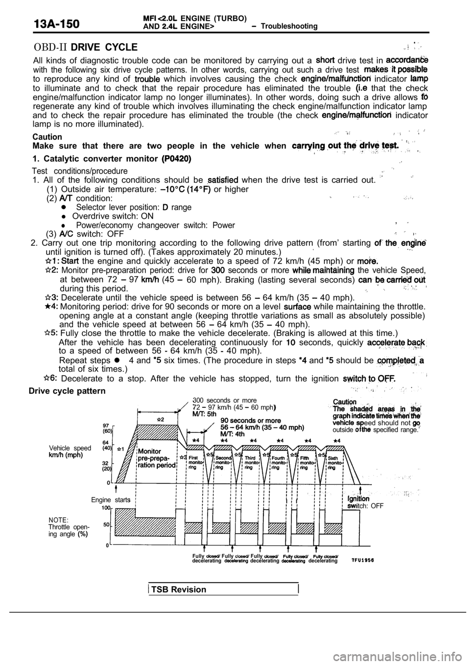
OBD-IIDRIVE CYCLE.
All kinds of diagnostic trouble code can be monitor ed by carrying out a drive test in
with the following six drive cycle patterns. In other words, carrying out such a drive test
to reproduce any kind of which involves causing the check indicator
to illuminate and to check that the repair procedur e has eliminated the trouble that the check
engine/malfunction indicator lamp no longer illumin ates). In other words, doing such a drive allows
regenerate any kind of trouble which involves illuminating the check engine/malfunction indicator lamp
and to check the repair procedure has eliminated th e trouble (the check
indicator
lamp is no more illuminated).
Caution
Make sure that there are two people in the vehicle when
1. Catalytic converter monitor
Test conditions/procedure
1. All of the following conditions should be when the drive test is carried out.
(1) Outside air temperature: or higher
(2)
condition:
Selector lever position: range
l Overdrive switch: ON
lPower/economy changeover switch: Power,
(3) switch: OFF
2. Carry out one trip monitoring according to the f ollowing drive pattern (from’ starting
until ignition is turned off). (Takes approximately 20 minutes.)
the engine and quickly accelerate to a speed of 72 km/h (45 mph) or
Monitor pre-preparation period: drive for seconds or more the vehicle Speed,
at between 72 97 (45
during this period.60 mph). Braking (lasting several seconds) . .,
Decelerate until the vehicle speed is between 56 64 km/h (35 40 mph).
Monitoring period: drive for 90 seconds or more on
a level while maintaining the throttle.
opening angle at a constant angle (keeping throttle variations as small as absolutely possible)
and the vehicle speed at between 56
64 km/h (35 40 mph).
Fully close the throttle to make the vehicle decel erate. (Braking is allowed at this time.)
After the vehicle has been decelerating continuousl y for
seconds, quickly
to a speed of between 56 64 km/h (35 40 mph).
Repeat steps l 4 and
six times. (The procedure in steps and should be
total of six times.)
Decelerate to a stop. After the vehicle has stoppe d, turn the ignition
Drive cycle pattern
300 seconds or more
72 97 km/h (45 60 mph)
eed should not outside specified range.’
Vehicle speed
NOTE:Throttle open-ing angle
0
itch: OFF
Engine startsI I
Fully Fully Fully decelerating decelerating decelerating
TSB Revision
Page 538 of 2103

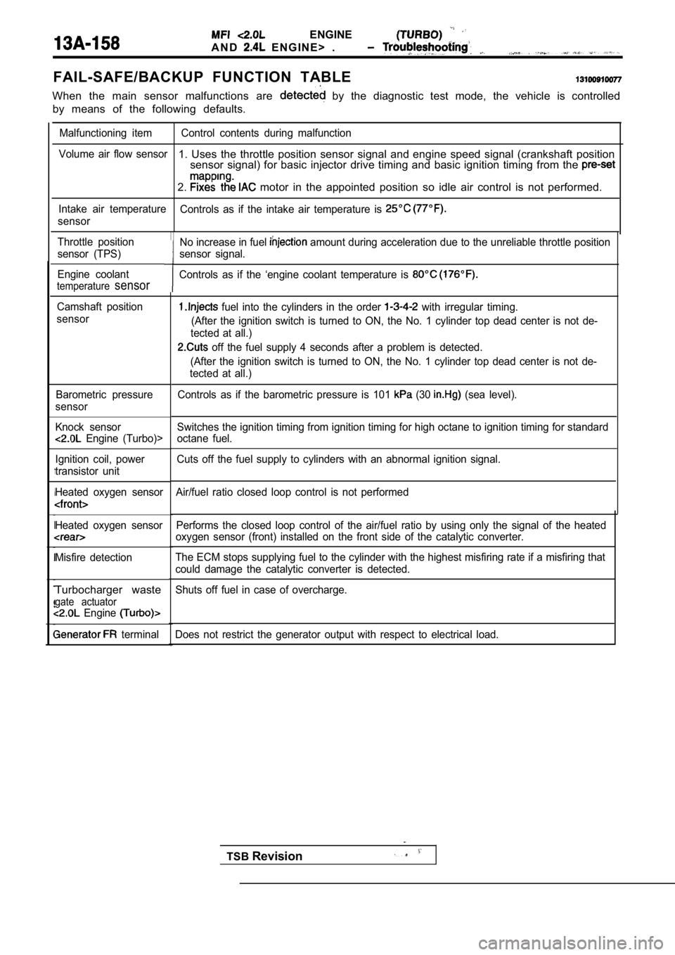
ENGINE
A N D E N G I N E > .
FAIL-SAFE/BACKUP FUNCTION TABLE
When the main sensor malfunctions are by the diagnostic test mode, the vehicle is controlled
by means of the following defaults.
Malfunctioning item Control contents during malfunct ion
Volume air flow sensor
1. Uses the throttle position sensor signal and eng ine speed signal (crankshaft position
sensor signal) for basic injector drive timing and basic ignition timing from the
2. motor in the appointed position so idle air contro l is not performed.
Intake air temperature
Controls as if the intake air temperature is
sensor
Throttle position
sensor (TPS)
Engine coolant
temperaturesensor
Camshaft position
sensor
Barometric pressure
sensor
Knock sensor
Engine (Turbo)>
Ignition coil, power
transistor unit
Heated oxygen sensor
Heated oxygen sensor
Misfire detection
Turbocharger waste
gate actuator Engine
terminal Performs the closed loop control of the air/fuel ra
tio by using only the signal of the heated
oxygen sensor (front) installed on the front side o f the catalytic converter.
The ECM stops supplying fuel to the cylinder with t he highest misfiring rate if a misfiring that
could damage the catalytic converter is detected.
Shuts off fuel in case of overcharge.
Does not restrict the generator output with respect to electrical load.
No increase in fuel amount during acceleration due to the unreliable throttle position
sensor signal.
Controls as if the ‘engine coolant temperature is
fuel into the cylinders in the order with irregular timing.
(After the ignition switch is turned to ON, the No. 1 cylinder top dead center is not de-
tected at all.)
off the fuel supply 4 seconds after a problem is d etected.
(After the ignition switch is turned to ON, the No. 1 cylinder top dead center is not de-
tected at all.)
Controls as if the barometric pressure is 101
(30 (sea level).
Switches the ignition timing from ignition timing f or high octane to ignition timing for standard
octane fuel.
Cuts off the fuel supply to cylinders with an abnor mal ignition signal.
Air/fuel ratio closed loop control is not performed
TSB Revision