1990 MITSUBISHI SPYDER length
[x] Cancel search: lengthPage 30 of 2103
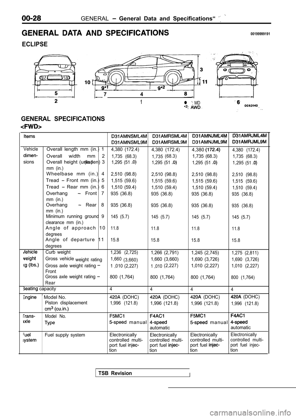
GENERAL General Data and Specifications“
00199999191
ECLIPSE
74
1l ‘: MD
.
GENERAL SPECIFICATIONS
VehicleOverall length mm (in.) 14,380 (172.4)4,380 (172.4)4,3804,380 (172.4)
Overall width mm 21,735 (68.3) 1,735
sions(in.) (68.3)
1,735 (68.3)1,735 (68.3)
Overall height (unladen) 31,295 (51 1,295 (51 1,295 (51 1,295(51
mm (in.)
W h e e l b a s e m m ( i n . ) 42,510 (98.8)
2,510 (98.8)2,510 (98.8)2,510 (98.8)
Tread Front mm (in.) 51,515 (59.6)
1,515 (59.6) 1,515 (59.6)1,515 (59.6)
Tread Rear mm (in.) 61,510 (59.4)
1,510 (59.4) 1,510 (59.4)1,510 (59.4)
Overhang Front 7935 (36.8)
935 (36.8) 935 (36.8)935 (36.8)
mm (in.)
Overhang Rear 8935 (36.8) 935 (36.8) 935 (36.8)935 (36.8)
mm (in.)
Minimum running ground 9145 (5.7) 145 (5.7) 145 (5.7)145 (5.7)
clearance mm (in.)
A n g l e o f a p p r o a c h 1 011.8 11.8 11.811.8
degrees
A n g l e o f d e p a r t u r e 1 115.8
15.8 15.815.8
degrees
Curb weight1,236 (2,725)1,266 (2,791) 1,245 (2,745)1,275 (2,811)
Gross vehicle
weight rating1,660(3,660)1,660 (3,660) 1,690 (3,726)1,690 (3,726)
Gross axle weight rating1 ,010 (2,227)1 ,010(2,227)1,010 (2,227)1,010 (2,227)
Front
Gross axle weight rating
800 (1,764) 800 (1,764) 800 (1,764)800 (1,764)
Rear
capacity4 4 44
Model No. (DOHC) (DOHC) (DOHC) (DOHC)
Piston displacement
1,996 (121.8)1,996 (121.8) 1,996 (121.8)1,996 (121.8)
Model No.
m a n u a l m a n u a l
automatic automatic
Fuel supply system
Electronically
Electronically ElectronicallyElectronically
controlled multi- controlled multi- controlled multi-controlled multi-
port fuel port fuel port fuel port fuel injec-
tion
tion tiontion
TSB RevisionI
Page 31 of 2103
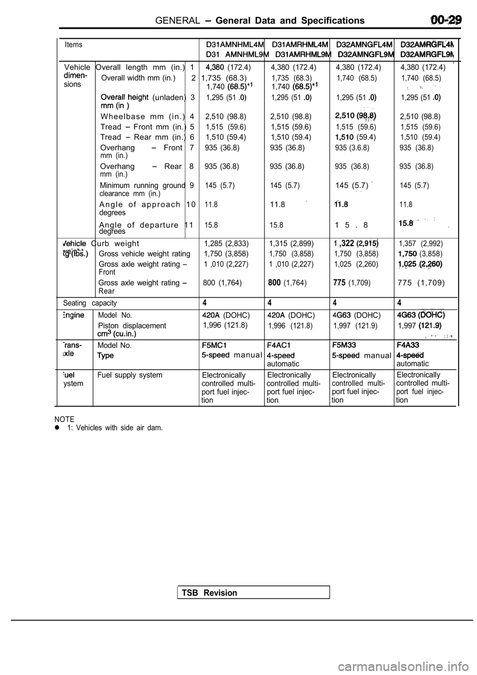
GENERAL General Data and Specifications
Items
,Vehicle Overall length mm (in.) 1 (172.4) 4,380 (172.4) 4,380 (172.4) 4,380 (172.4)
sionsOverall width mm (in.)2 1,735 (68.3)
1,740
1,735 (68.3)
1,740
1,740 (68.5) 1,740 (68.5)
(unladen) 31,295 (51 1,295 (51 1,295 (51 1,295 (51
W h e e l b a s e m m ( i n . ) 42,510 (98.8) 2,510 (98.8)2,510 (98.8)
Tread Front mm (in.) 51,515 (59.6)1,515 (59.6)1,515 (59.6) 1,515 (59.6)
Tread Rear mm (in.) 61,510 (59.4) 1,510 (59.4) (59.4)1,510 (59.4)
Overhang Front 7935 (36.8) 935 (36.8)935 (3.6.8) 935 (36.8)
mm (in.)
Overhang Rear 8935 (36.8) 935 (36.8)935 (36.8) 935 (36.8)
mm (in.)
Minimum running ground 9145 (5.7) 145 (5.7)145 (5.7) 145 (5.7)
clearance mm (in.)
A n g l e o f a p p r o a c h 1 011.811.811.8
degrees
A n g l e o f d e p a r t u r e 1 115.8 15.81 5 . 8degrees
Curb weight1,285 (2,833) 1,315 (2,899) ,322 1,357 (2,992)
Gross vehicle weight rating 1,750 (3,858)1,750 (3,858) 1,750 (3,858)(3,858)
Gross axle weight rating 1 ,010 (2,227) 1 ,010 (2,227) 1,025 (2,260)
Front
Gross axle weight rating 800 (1,764)800(1,764)775(1,709)775 (1,709)
Rear
Seating capacity
Model No.
Piston displacement
Model No.
Fuel supply system
ystem
4 444
(DOHC) (DOHC) (DOHC)
1,996 (121.8)1,996 (121.8) 1,997 (121.9)1,997
m a n u a l manual
automatic automatic
Electronically Electronically Electronically Electronically
controlled multi- controlled multi-
controlled multi-controlled multi-
port fuel injec- port fuel injec-port fuel injec-
port fuel injec-
tion tion tion tion
NOTE
l 1: Vehicles with side air dam.
TSB Revision
Page 32 of 2103
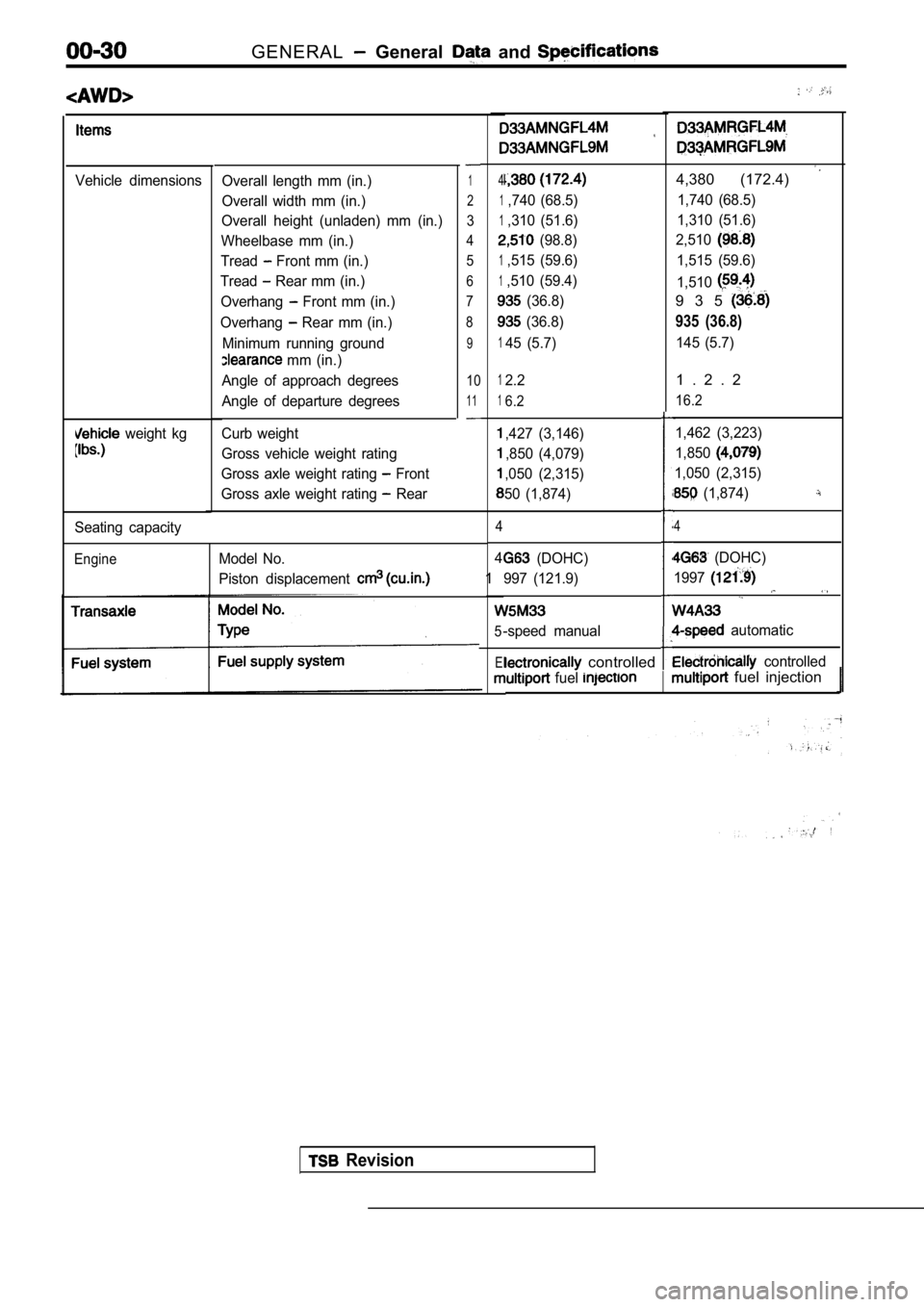
GENERAL General and
Vehicle dimensions
weight kg
Overall length mm (in.)
Overall width mm (in.)
Overall height (unladen) mm (in.)
Wheelbase mm (in.)
Tread
Front mm (in.)
Tread
Rear mm (in.)
Overhang
Front mm (in.)
Overhang
Rear mm (in.)
Minimum running ground
mm (in.)
Angle of approach degrees
Angle of departure degrees
Curb weight
Gross vehicle weight rating
Gross axle weight rating
Front
Gross axle weight rating
Rear
1
2
3
4 5
6
7
8
9
10
11
Seating capacity
EngineModel No.
Piston displacement
4
1,740 (68.5)
1,310 (51.6)
(98.8)
1,515 (59.6)
1,510 (59.4)
(36.8)
(36.8)
145 (5.7)
4,380 (172.4)
1,740 (68.5)
1,310 (51.6)
2,510
1,515 (59.6)
1,510
9 3 5
935 (36.8)
145 (5.7)
12.2
16.2
,427 (3,146)
,850 (4,079)
,050 (2,315)
50 (1,874)
4
4
1
5
El
1 . 2 . 2
16.2
1,462 (3,223)
1,850
1,050 (2,315)
(1,874)
4
(DOHC)
997 (121.9)
-speed manual
(DOHC)
1997
automatic
controlled controlled
fuel fuel injection
Revision
Page 33 of 2103
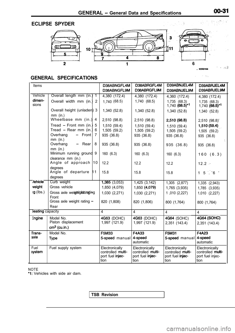
GENERAL General Data and Specifications
ECLIPSE SPYDER
GENERAL SPECIFICATIONS
6
.
Items
VehicleOverall length mm (in.) 14,380 (172.4) 4,380 (172.4)
4,360 (172.4)4,380 (172.4)
Overall width mm (in.) 21,740(68.5)
1,740 (68.5)
1,735 (68.3)1,7401,735 (68.3)sions
1,740
Overall height (unladen) 31,340 (52.8)1,340 (52.8)
1,340 (52.8)1,340 (52.8)
mm (in.)
W h e e l b a s e m m ( i n . ) 42,510 (98.8) 2,510 (98.8)2,510 (98.8)’
Tread Front mm (in.) 51,510 (59.4) 1,510 (59.4)
1,510 (59.4)
Tread Rear mm (in.) 61,505 (59.2) 1,505 (59.2)
1,505 (59.2)1,505 (59.2)Overhang Front 7935 (36.8) 935 (36.8)
935 (36.8)935 (36.8)
mm (in.)
Overhang Rear 8935 (36.8) 935 (36.8)9 3 5 ( 3 6 . 8 )935 (36.8)
mm (in.)
Minimum running ground 9160 (6.3) 160 (6.3)
160 (6.3)1 6 0 ( 6 . 3 )
clearance mm (in.)
A n g l e o f a p p r o a c h 1 012.2 12.2
12.21 2 . 2
degrees
A n g l e o f d e p a r t u r e 1 115.8 15.8
15.81 5 . 6 ’
degrees
Curb weight (3,053)1,425 (3,142)1,305 (2,877) 1,335 (2,943)
Gross vehicle
1,765 (3,935)1,785 (3,935)
(Ibs.)weight rating1,850 (4,079)
1,850Gross axle weight rating 1,030 (2,271)1,030 (2,271)1 ,010 (2,227) 1,010 (2,227)
Front
Gross axle weight rating
820 (1,808) 820 (1,806)
800 (1,764)800 (1,764)
Rear
capacity
Model No.
Piston displacement
Model No.
FuelFuel supply system
NOTE
Vehicles with side air dam. 4
444
(DOHC) (DOHC) (SOHC)
1,997 (121.9)
1,997 (121.9)
2,351 (143.4)2,351 (143.4)
m a n u a l m a n u a l
automatic automatic
Electronically Electronically Electronically Electronically
controlled
controlledcontrolledcontrolled
port fuel port fuel port fuel port fuel injec-
tion tion tion tion
TSB Revision
Page 52 of 2103

GENERAL Maintenance Service
2.Check the wheel cylinder boots for evidence, a’ brake
fluid leak. Visually check the
boots for tears or
cracks. (A slight amount of fluid on the boot may not
be a leak, but may be preservative assembly.)
Caution
The shoes for the right and left be,
replaced at the same time.
Never split or intermix brake
sets.
All four shoes must be replaced as a set.
Thickness of lining
Limit: 1.0 mm in.)
17. BRAKE HOSES (Check for
leaks)
Check of brake hoses and tubing should be
brake service operations.
The hoses should be checked for:
1.Correct length, severe surface cracking, pulling, scuffing
or worn spots. (If the fabric casing of the hoses i s exposed
by cracks of abrasion in the rubber hose cover, the hoses
should be replaced. Eventual deterioration of may
occur with possible bursting failure.)
2. Faulty installation, casing twisting or interfer ence
wheel,’ tire or chassis.
18. BALL JOINT AND STEERING SEALS
(Check for grease leaks damage)
1. These components, which are permanently lubricat ed
at the factory, do not require periodic lubrication. Damaged
seals and boots should be replaced to prevent leakage
or contamination of the grease.
2.Check the dust cover and boots for proper sealing, leakage
and damage. Replace them if defective.
19. DRIVE SHAFT BOOTS (Check for leaks
and damage)
1. These components, which are permanently lubricat ed
at the factory, do not require periodic Damaged
boots should be replaced to prevent leakage or contamina-
tion of the grease.
2.Check the boots for proper sealing, leakage and damage.
Replace it if defective.
AXLE OIL (Check oil level)-AWD
Remove the filler plug and check the oil level at bottom of
filler hole. If the oil level is slightly below the filler hole, it
is in satisfactory condition.
Page 63 of 2103
ENGINE Service Specifications
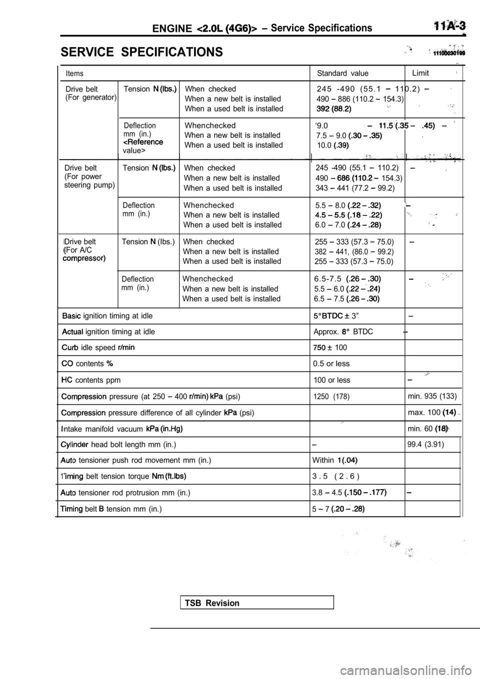
SERVICE SPECIFICATIONS
I
1
Items
Drive beltTensionWhen checked
(For generator) When a new belt is installed
When a used belt is installed
DeflectionWhenchecked
mm (in.)When a new belt is installed
value>When a used belt is installed
Drive belt Tension
When checked
(For power When a new belt is installed
steering pump) When a used belt is installed
DeflectionWhenchecked
mm (in.)When a new belt is installed
When a used belt is installed
Drive belt Tension
(Ibs.) When checked
[For A/C When a new belt is installed
When a used belt is installed
DeflectionWhenchecked
mm (in.)When a new belt is installed
When a used belt is installed
ignition timing at idle
ignition timing at idle
idle speed
contents
contents ppm
pressure (at 250 400 (psi)
pressure difference of all cylinder (psi)
ntake manifold vacuum
head bolt length mm (in.)
tensioner push rod movement mm (in.)
belt tension torque
tensioner rod protrusion mm (in.)
belt tension mm (in.)
Standard valueLimit
2 4 5 - 4 9 0 ( 5 5 . 1 1 1 0 . 2 )
490 886 (110.2 154.3)
‘9.0
7.5 9.0
10.0
.245 -490 (55.1 110.2)
490 154.3)
343
441 (77.2 99.2)
5.5
8.0
6.0 7.0
255 333 (57.3 75.0)
382 441, (86.0 99.2)
255 333 (57.3 75.0)
6 . 5 - 7 . 5
5.5 6.0
6.5 7.5
3”
Approx. BTDC
100
0.5 or less
100 or less
1250 (178)min. 935 (133)
max. 100
min. 60
99.4 (3.91)
Within
3 . 5 ( 2 . 6 )
3.8 4.5
5 7
TSB Revision
Page 97 of 2103
ENGINE Timing
(22-44
A
tensioner
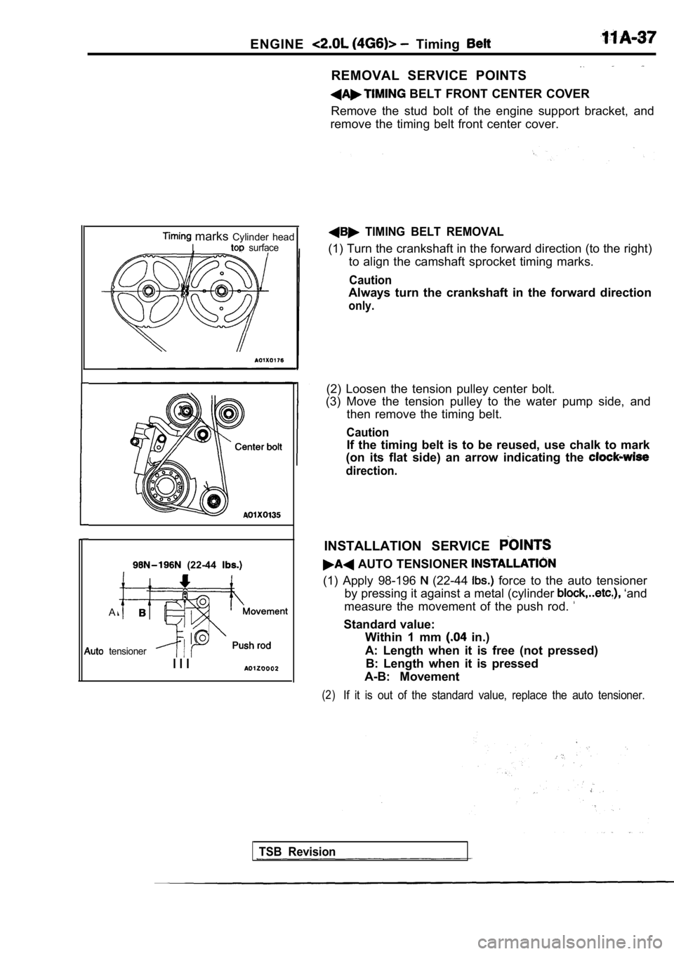
marks Cylinder headI surface
I I I
REMOVAL SERVICE POINTS
BELT FRONT CENTER COVER
Remove the stud bolt of the engine support bracket, and
remove the timing belt front center cover.
TIMING BELT REMOVAL
(1) Turn the crankshaft in the forward direction (t o the right)
to align the camshaft sprocket timing marks.
Caution
Always turn the crankshaft in the forward direction
only.
(2) Loosen the tension pulley center bolt.
(3) Move the tension pulley to the water pump side, and
then remove the timing belt.
Caution
If the timing belt is to be reused, use chalk to ma rk
(on its flat side) an arrow indicating the
direction.
INSTALLATION SERVICE
AUTO TENSIONER
(1) Apply 98-196 (22-44 force to the auto tensioner
by pressing it against a metal (cylinder
‘and
measure the movement of the push rod.
Standard value: Within 1 mm
in.)
A: Length when it is free (not pressed) B: Length when it is pressed
A-B: Movement
(2)If it is out of the standard value, replace the aut o tensioner.
TSB Revision
Page 100 of 2103
E N G I N E Belt
Auto tensioner
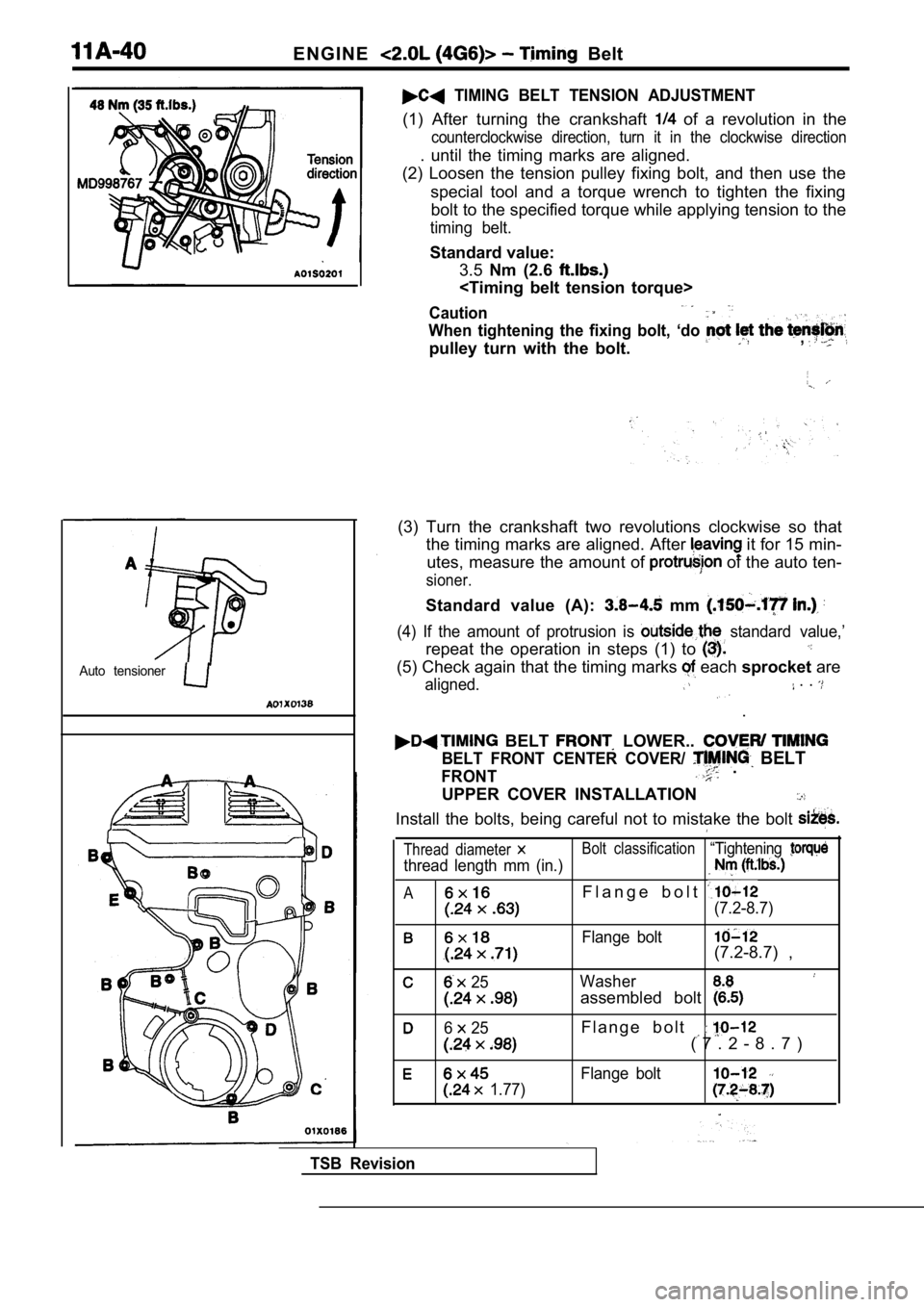
TIMING BELT TENSION ADJUSTMENT
(1) After turning the crankshaft of a revolution in the
counterclockwise direction, turn it in the clockwise direction
. until the timing marks are aligned.
(2) Loosen the tension pulley fixing bolt, and then use the
special tool and a torque wrench to tighten the fix ing
bolt to the specified torque while applying tension to the
timing belt.
Standard value:
3.5 Nm (2.6
Caution
When tightening the fixing bolt, ‘do
pulley turn with the bolt.,
(3) Turn the crankshaft two revolutions clockwise s o that
the timing marks are aligned. After
it for 15 min-
utes, measure the amount of
of the auto ten-
sioner.
Standard value (A): mm
(4) If the amount of protrusion is standard value,’
repeat the operation in steps (1) to
(5) Check again that the timing marks each sprocket are
aligned. . .
.
BELT LOWER..
BELT FRONT CENTER COVER/ BELT
FRONT .
UPPER COVER INSTALLATION
Install the bolts, being careful not to mistake the bolt
Thread diameter Bolt classification“Tightening
thread length mm (in.)
AF l a n g e b o l t
(7.2-8.7)
Flange bolt(7.2-8.7) ,
25Washer
assembled bolt
6 25F l a n g e b o l t
( 7 . 2 - 8 . 7 )
Flange bolt
1.77)
TSB Revision