1990 MITSUBISHI SPYDER length
[x] Cancel search: lengthPage 107 of 2103
ENGINE OVERHAUL ‘Specifications
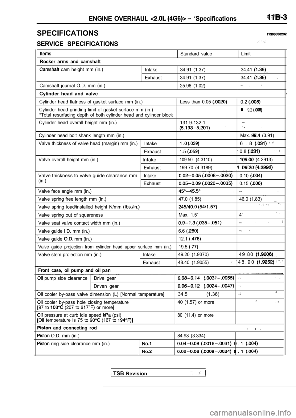
SPECIFICATIONS
SERVICE SPECIFICATIONS
Rocker arms and camshaft
cam height mm (in.)
Camshaft journal O.D. mm (in.)
Cylinder head and valve
Standard valueLimit
Intake 34.91 (1.37) 34.41
Exhaust 34.91 (1.37) 34.41
25.96 (1.02)
Cylinder head flatness of gasket surface mm (in.) Le ss than 0.05 0.2
Cylinder head grinding limit of gasket surface mm (in.)l 9.2
*Total resurfacing depth of both cylinder head and cylinder block
Cylinder head overall height mm (in.) 131.9-132.1
Cylinder head bolt shank length mm (in.) Max. (3.91)
Valve thickness of valve head (margin) mm (in.) Intake
16 . 8
Exhaust1.5 0.8
Valve overall height mm (in.)Intake109.50 (4.3110) (4.2913)
Exhaust 199.70 (4.3189)
.
Valve thickness to valve guide clearance mmIntake0.10
(in.)Exhaust0.15
Valve face angle mm (in.),
Valve spring free length mm (in.) 47.0 (1.85) 46.0 (1
.83)
Valve spring load/installed height N/mm
Valve spring out of squarenessMax. 1.5”4”
Valve seat valve contact width mm (in.)
Valve guide I.D. mm (in.) 6.6
Valve guide mm (in.)12.1
Valve guide projection from cylinder head upper sur
face mm (in.)19.5
Valve stem projection mm (in.) Intake 49.20 (1.9370)4 9 . 8 0 .
Exhaust48.40 (1.9055) ‘ 4 8 . 9 0
Front case, oilpump and oilp a n
pump side clearance Drive gear
Driven gear
cooler by-pass valve dimension (L) [Normal tempera
ture]34.5 (1.36)
cooler by-pass hole closing temperature 40 (1.57) or more
97 to (207 to or more]
pressure at curb idle speed (psi)80 (11.4) or more
Oil temperature is 75 to (167 to
and connecting rod ,
O.D. mm (in.)
84.98 (3.334)
ring side clearance mm (in.) 0 . 1
0 . 1
TSB Revision
Page 108 of 2103
![MITSUBISHI SPYDER 1990 Service Repair Manual ENGINE OVERHAUL
Items Standard value
Piston ring end gap mm (in.)
Piston pin O.D. mm (in.)
0 . 8
Oil 9 . 8
21
Piston pin press-in load (Ibs.)
[Room temperature]
Crankshaft pin MITSUBISHI SPYDER 1990 Service Repair Manual ENGINE OVERHAUL
Items Standard value
Piston ring end gap mm (in.)
Piston pin O.D. mm (in.)
0 . 8
Oil 9 . 8
21
Piston pin press-in load (Ibs.)
[Room temperature]
Crankshaft pin](/manual-img/19/57345/w960_57345-107.png)
ENGINE OVERHAUL
Items Standard value
Piston ring end gap mm (in.)
Piston pin O.D. mm (in.)
0 . 8
Oil 9 . 8
21
Piston pin press-in load (Ibs.)
[Room temperature]
Crankshaft pin oil clearance mm (in.) 17,500
Connecting rod big end side clearance mm (in.)
Crankshaft, flywheel and drive plate
Bearing cap bolt shank length mm (in.)
0 . 4
Crankshaft end play mm (in.)
Crankshaft journal O.D. mm (in.) 0 . 2 5
57 (2.24)
pin O.D. mm (in.) 42 (1.77)
Crankshaft journal oil clearance mm (in.)
to cylinder clearance mm (in.)
0 . 1
block flatness of gasket surface mm (in.) 0.05 0.1
block grinding limit of gasket surface mm (in.)l 0.2‘Total resurfacing depth of both cylinder head and cylinder block
block overall height mm (in.)283.9-284.1
(11.177-11.185)
block I.D. mm (in.) 85.0 (3.35)
TSBRevision
REWORK DIMENSIONS
Items
Cylinder head and valve
Oversize rework dimensions of valve guide0.05 O.S.
hole (both intake and exhaust) mm (in.) 0.25 O.S.
0.50
Intake oversize rework 0.3
dimensions of valve seat hole mm (in.)
0.6 O.S.
Exhaust oversize rework dimensions of valve 0.3 O.S.
seat hole
mm (in.)0.6 O.S.
Crankshaft, flywheel and drive plate
Crankshaft out of roundness and taper of journal an d pin mm (in.)
Standard value
12.25-12.27 ,
,
Max. 0.01
NOTE
O.D.: Outer diameter
I.D.: Inner diameter
Oversize diameter
Page 142 of 2103
11 E N G I N E O V E R H A U L Cylinder Head
Identification mark
RETAINER LOCK . .
The ‘valve spring,if excessively, compressed, causes the
bottom end of retainer to be in contact with, and d amage,:
the stem seal.
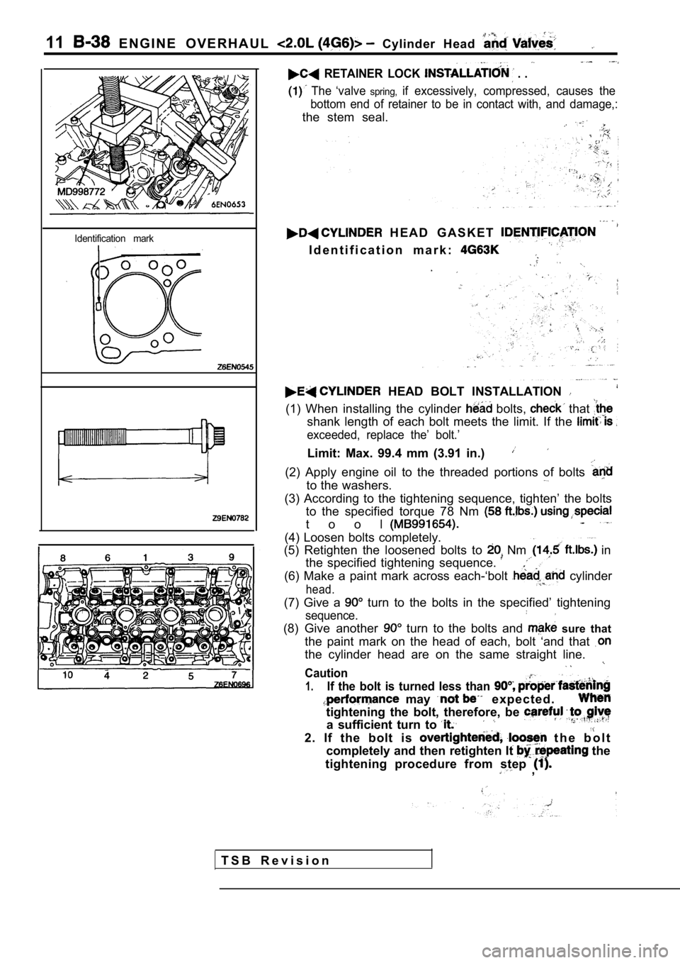
H E A D G A S K E T
I d e n t i f i c a t i o n m a r k :
HEAD BOLT INSTALLATION
(1) When installing the cylinder bolts, that
shank length of each bolt meets the limit. If the
exceeded, replace the’ bolt.’
Limit: Max. 99.4 mm (3.91 in.)
(2) Apply engine oil to the threaded portions of bo lts
to the washers.
(3) According to the tightening sequence, tighten’ the bolts
to the specified torque 78 Nm
t o o l
(4) Loosen bolts completely.
(5) Retighten the loosened bolts to
Nm in
the specified tightening sequence.
(6) Make a paint mark across each-‘bolt cylinder
head.
(7) Give a turn to the bolts in the specified’ tightening
sequence.
(8) Give another turn to the bolts and sure that
the paint mark on the head of each, bolt ‘and that
the cylinder head are on the same straight line.
Caution
1.If the bolt is turned less than
may e x p e c t e d .
tightening the bolt, therefore, be
a sufficient turn to
2. If the bolt is t h e b o l t
completely and then retighten It
the
tightening procedure from step
,
T S B R e v i s i o n
Page 143 of 2103
ENGINE OVERHAUL Cylinder Head and
Valve seat
contact
Margin
I
I
Free
height
INSPECTION
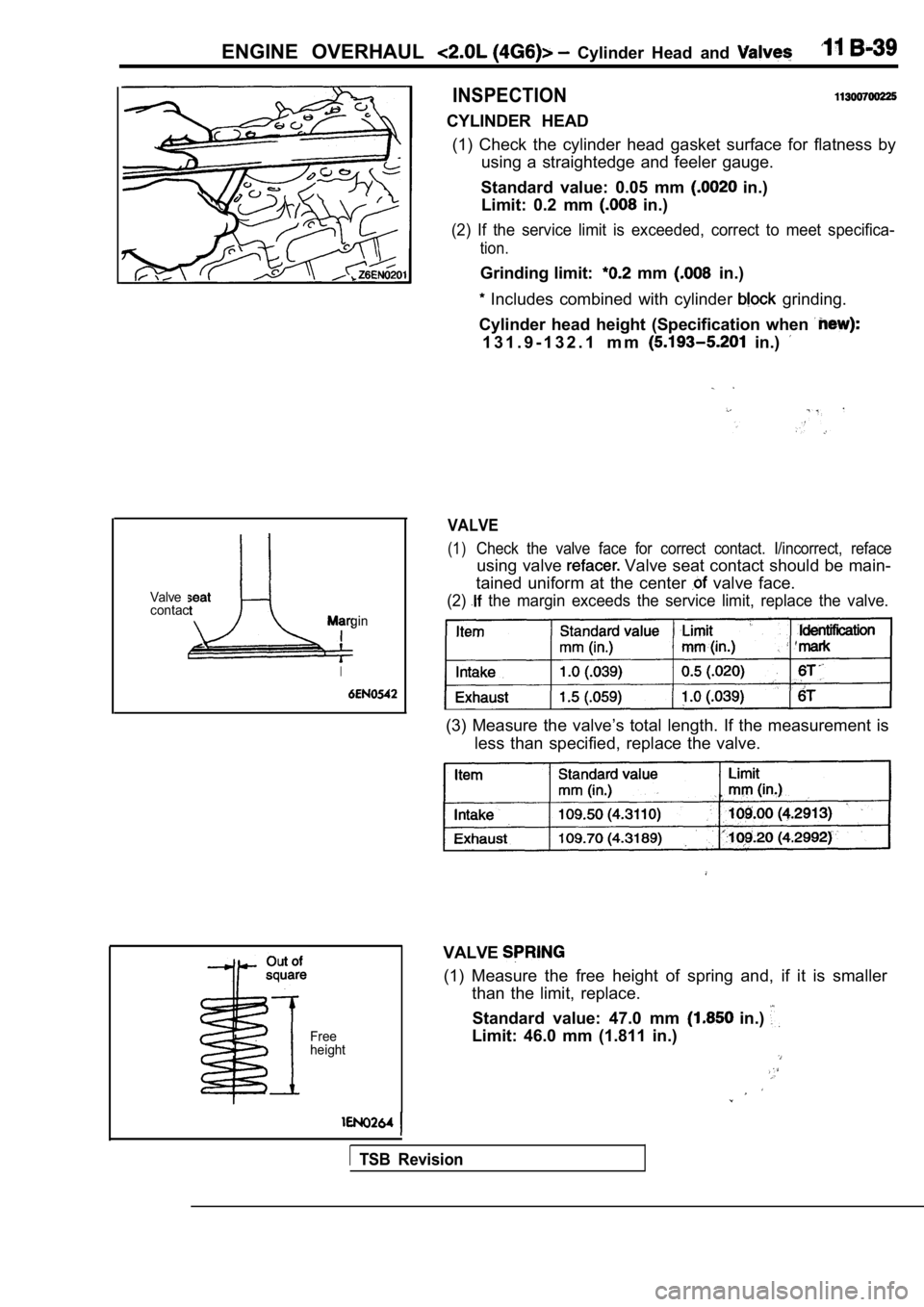
CYLINDER HEAD (1) Check the cylinder head gasket surface for flat ness by
using a straightedge and feeler gauge.
Standard value: 0.05 mm
in.)
Limit: 0.2 mm
in.)
(2) If the service limit is exceeded, correct to me et specifica-
tion.
Grinding limit: mm in.)
Includes combined with cylinder grinding.
Cylinder head height (Specification when
1 3 1 . 9 - 1 3 2 . 1 m m in.)
VALVE
(1)Check the valve face for correct contact. I/incorre ct, reface
using valve Valve seat contact should be main-
tained uniform at the center
valve face.
(2) the margin exceeds the service limit, replace the valve.
(3) Measure the valve’s total length. If the measurement is
less than specified, replace the valve.
VALVE
(1) Measure the free height of spring and, if it is smaller
than the limit, replace.
Standard value: 47.0 mm
in.)
Limit: 46.0 mm (1.811 in.)
TSB Revision
Page 152 of 2103
Front Case, ENGINE OVERHAUL Shaft and. Pan
Crank pulley side
8 mm bolts
Oil pan viewed from lower side
Drain pigasket
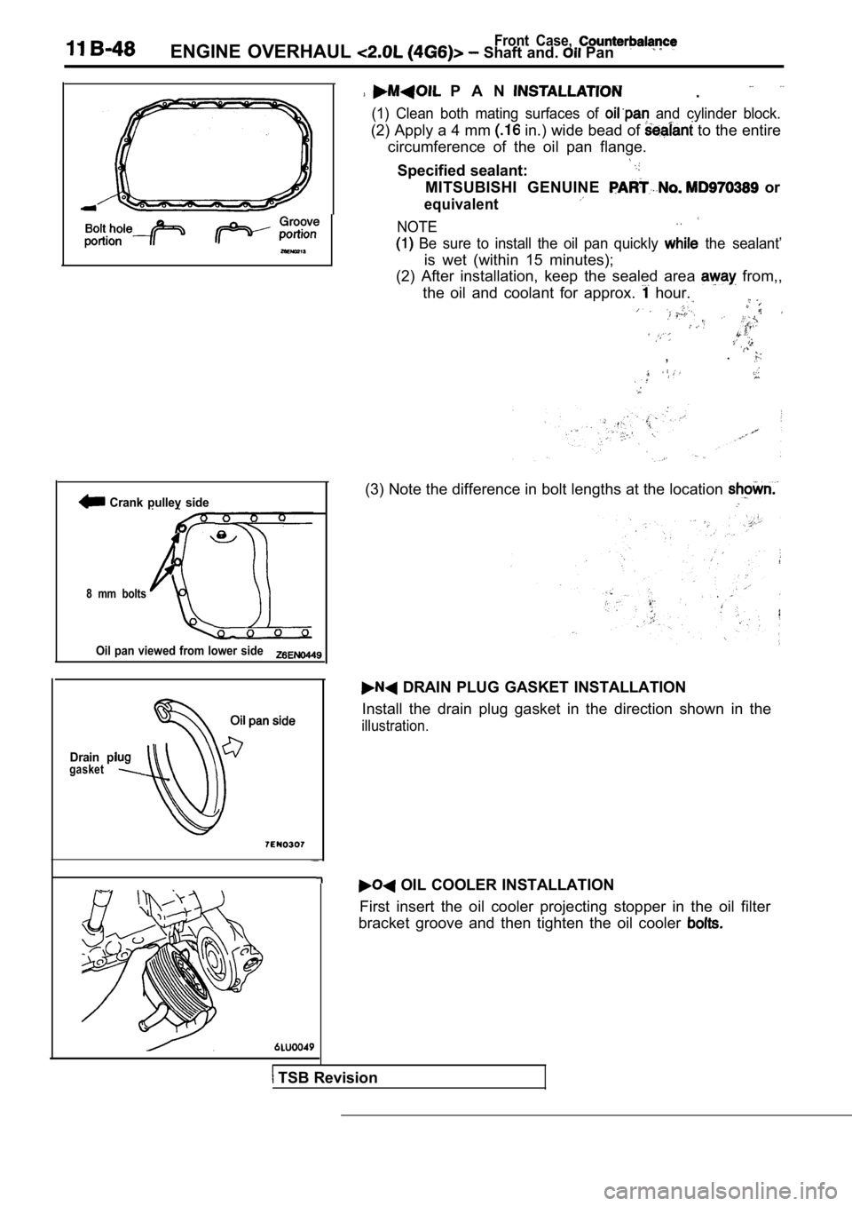
P A N .
(1) Clean both mating surfaces of and cylinder block.
(2) Apply a 4 mm in.) wide bead of to the entire
circumference of the oil pan flange.
Specified sealant:
MITSUBISHI GENUINE or
equivalent
NOTE. .
Be sure to install the oil pan quickly the sealant’
is wet (within 15 minutes);
(2) After installation, keep the sealed area
from,,
the oil and coolant for approx.
hour.
, .
(3) Note the difference in bolt lengths at the loca
tion
DRAIN PLUG GASKET INSTALLATION
Install the drain plug gasket in the direction show n in the
illustration.
OIL COOLER INSTALLATION
First insert the oil cooler projecting stopper in t he oil filter
bracket groove and then tighten the oil cooler
TSB Revision
Page 160 of 2103
11ENGINE OVERHAUL Piston and
No.
Notch
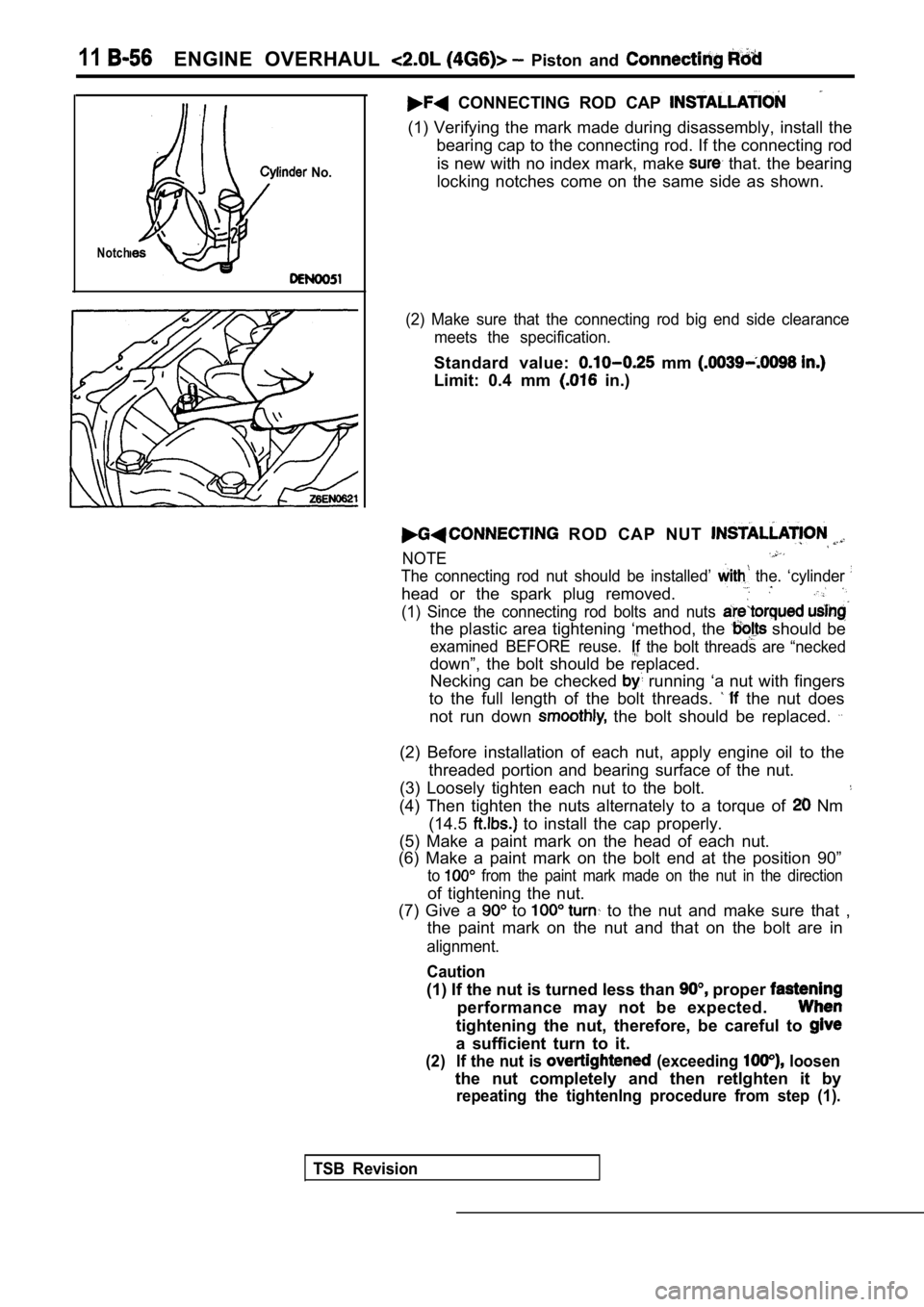
CONNECTING ROD CAP
(1) Verifying the mark made during disassembly, install the
bearing cap to the connecting rod. If the connectin g rod
is new with no index mark, make
that. the bearing
locking notches come on the same side as shown.
(2) Make sure that the connecting rod big end side clearance
meets the specification.
Standard value: mm
Limit: 0.4 mm in.)
ROD CAP NUT
NOTE
The connecting rod nut should be installed’ the. ‘cylinder
head or the spark plug removed.
(1) Since the connecting rod bolts and nuts
the plastic area tightening ‘method, the should be
examined BEFORE reuse. the bolt threads are “necked
down”, the bolt should be replaced. Necking can be checked
running ‘a nut with fingers
to the full length of the bolt threads.
the nut does
not run down
the bolt should be replaced.
(2) Before installation of each nut, apply engine o il to the
threaded portion and bearing surface of the nut.
(3) Loosely tighten each nut to the bolt.
(4) Then tighten the nuts alternately to a torque o f Nm
(14.5
to install the cap properly.
(5) Make a paint mark on the head of each nut.
(6) Make a paint mark on the bolt end at the positi on 90”
to from the paint mark made on the nut in the direction
of tightening the nut.
(7) Give a
to to the nut and make sure that ,
the paint mark on the nut and that on the bolt are in
alignment.
Caution
(1) If the nut is turned less than proper
performance may not be expected.
tightening the nut, therefore, be careful to
a sufficient turn to it.
(2) If the nut is (exceeding loosen
the nut completely and then retlghten it by
repeating the tightenlng procedure from step (1).
TSB Revision
Page 162 of 2103
ENGINE OVERHAUL Piston Rod
1I
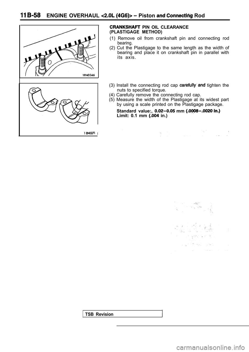
PIN OIL CLEARANCE
(PLASTIGAGE METHOD)
(1) Remove oil from crankshaft pin and connecting rod
bearing.
(2) Cut the Plastigage to the same length as the width of
bearing and place it on crankshaft pin in parallel with
i t s a x i s .
(3) Install the connecting rod cap
tighten the
nuts to specified torque.
(4) Carefully remove the connecting rod cap.
(5) Measure the width of the Plastigage at its wide st part
by using a scale printed on the Plastigage package.
Standard value:,
mm
Limit: 0.1 mm in.)
TSB Revision
Page 165 of 2103
![MITSUBISHI SPYDER 1990 Service Repair Manual E N G I N E O V E R H A U L
ed
(for No. tion mark
Upper and lower (for No.3)
Identification
mark
1
Shank length
[Example]
(1) If the measured value of a crankshaft
diameter is b MITSUBISHI SPYDER 1990 Service Repair Manual E N G I N E O V E R H A U L
ed
(for No. tion mark
Upper and lower (for No.3)
Identification
mark
1
Shank length
[Example]
(1) If the measured value of a crankshaft
diameter is b](/manual-img/19/57345/w960_57345-164.png)
E N G I N E O V E R H A U L
ed
(for No. tion mark
Upper and lower (for No.3)
Identification
mark
1
Shank length
[Example]
(1) If the measured value of a crankshaft
diameter is between 56.994 mm (2.2439
2.2441 in.), the journal is in the’
case the is also replaced by a
spare part, check the identification colors of the
journals painted on the
crankshaft. If the color’
is yellow, for example,.
journal is classified as
(2)
check the cylinder block bearing hole
mark stamped on the cylinder block.
If it is “O”, read the “Bearing identification column
to find the identification mark of the bearing to b e
used. In this case, it is “1”.
(4)
the bearings oil groove to the cylinder
block.
(5) Install the bearings having no oil to the bearing
caps.
CAP B E A R I N G C A P B O L T
INSTALLATION
(1) Install the bearing caps so that their arrows directed
to the timing belt side.
(2) Before installing the bearing cap bolts, check that the
shank length of each bolt meets the limit.
limit
is exceeded, replace the bolt.
(A): Max. 71.1 mm (2.79 in.)
(3) Apply engine oil to the threaded portion and be aring sur-
face of the bolt.
(4) Tighten the bolts to 25 Nm (16
in the specified
tightening sequence.
(5) Make a paint mark on the head of each bolt.
(6) Make a paint mark on the bearing cap at the pos ition
to from the paint mark made on the bolt in
the direction of tightening the bolt.
(7) According to the specified tightening sequence, give a
to turn to each bolt and make sure that the
paint mark on the bolt and that on the cap are in a lignment.
Caution
(1) If
thebolt is turned less than proper
performance may not be expected.
tightening the bolt, therefore, be careful to
a sufficient turn to it.
( 2 ) I f t h e b o l t i s
loosen the bolt completely and then retlghten
by repeating the tightening procedure from step
TSB Revision