Page 167 of 2103
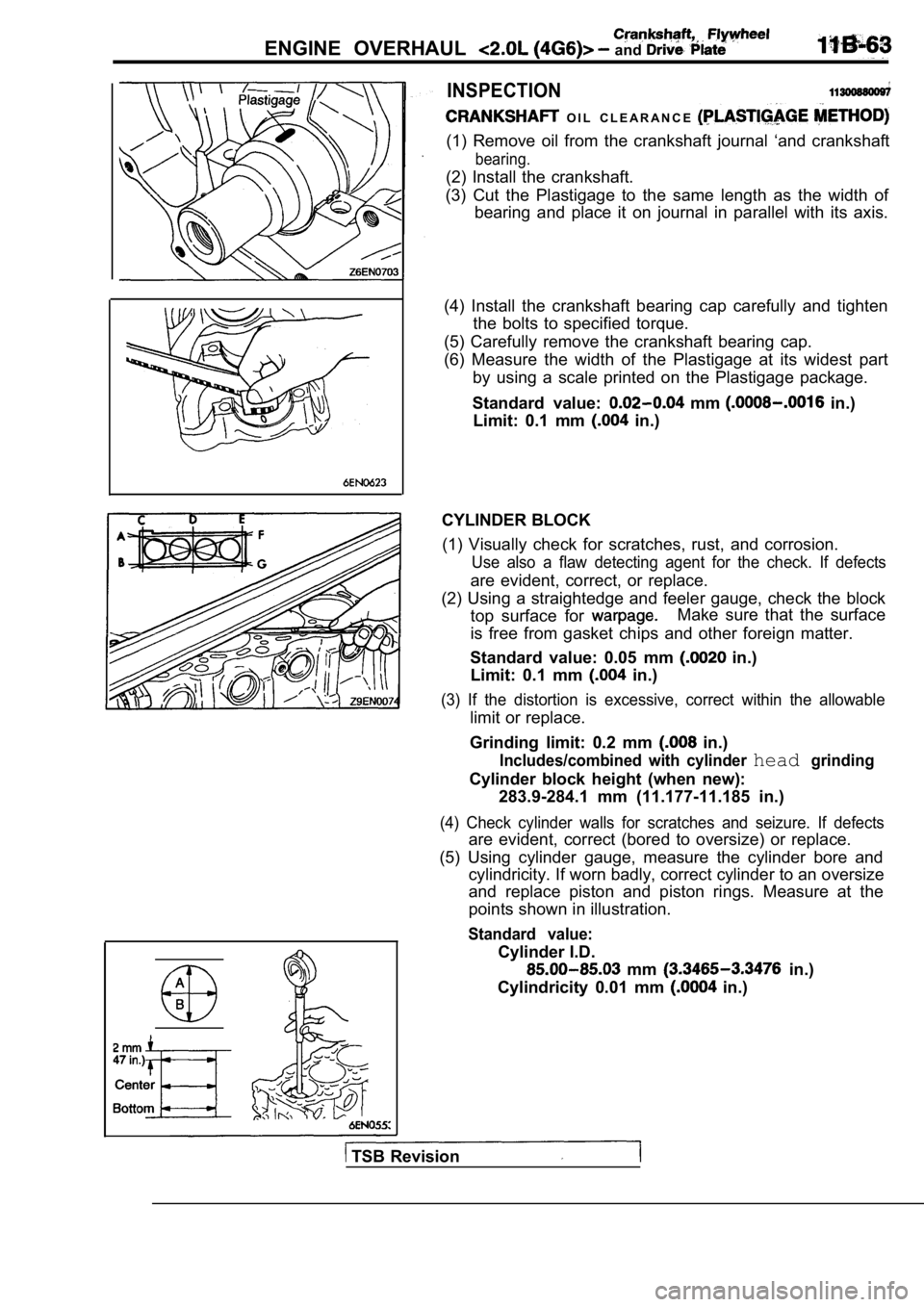
ENGINE OVERHAUL and
A
INSPECTION
O I L C L E A R A N C E
(1) Remove oil from the crankshaft journal ‘and crankshaft
bearing.
(2) Install the crankshaft.
(3) Cut the Plastigage to the same length as the wi dth of
bearing and place it on journal in parallel with it s axis.
(4) Install the crankshaft bearing cap carefully an d tighten
the bolts to specified torque.
(5) Carefully remove the crankshaft bearing cap.
(6) Measure the width of the Plastigage at its wide st part
by using a scale printed on the Plastigage package.
Standard value:
mm in.)
Limit: 0.1 mm
in.)
CYLINDER BLOCK (1) Visually check for scratches, rust, and corrosi on.
Use also a flaw detecting agent for the check. If d efects
are evident, correct, or replace.
(2) Using a straightedge and feeler gauge, check th e block
top surface for
Make sure that the surface
is free from gasket chips and other foreign matter.
Standard value: 0.05 mm
in.)
Limit: 0.1 mm
in.)
(3) If the distortion is excessive, correct within the allowable
limit or replace.
Grinding limit: 0.2 mm
in.)
Includes/combined with cylinder headgrinding
Cylinder block height (when new): 283.9-284.1 mm (11.177-11.185 in.)
(4) Check cylinder walls for scratches and seizure. If defects
are evident, correct (bored to oversize) or replace.
(5) Using cylinder gauge, measure the cylinder bore and
cylindricity. If worn badly, correct cylinder to an oversize
and replace piston and piston rings. Measure at the
points shown in illustration.
Standard value:
Cylinder I.D.
mm in.)
Cylindricity 0.01 mm
in.)
TSB Revision
Page 210 of 2103
ENGINE OVERHAUL . . . . .------- ----
ItemsStandard value
Valve margin mm (in.)
,
Exhaust
Valve length (Overall) mm (in.)Intake
Exhaust
(4.314-4.334)
Valve stem tip height mm (in.)
Intake48.04 (1.891)
Exhaust47.99 (1.889)
Valve stem diameter mm (in.)Intake5.934-5.952 ,
Exhaust
Valve stem to guide clearance mm (in.) Intake
Exhaust
guide inner diameter mm (in.)
spring free length mm (in.)
spring tension (valve closed) N/mm
0 . 0 7 6
0.101
46 (1.811)
spring tension (valve open) N/mm
spring number of coils mm (in.)
spring wire diameter mm (in.)
installed spring height mm (in.)
pump
pump clearance over rotors mm (in.)
pump cover out of flat mm (in.)
pump inner rotor thickness mm (in.)
pump outer rotor clearance mm (in.)
pump outer rotor diameter mm (in.)
pump outer rotor thickness mm (in.)
pump tip clearance between rotors mm (in.)
pressure at curb idle speed (psi)
7.35.
3.76
38.00 (1.496)
0.102
0 . 0 7 6
7.64
79.95 (3.148)
7.64
0.02
25 (4).
TSB Revision
Page 211 of 2103
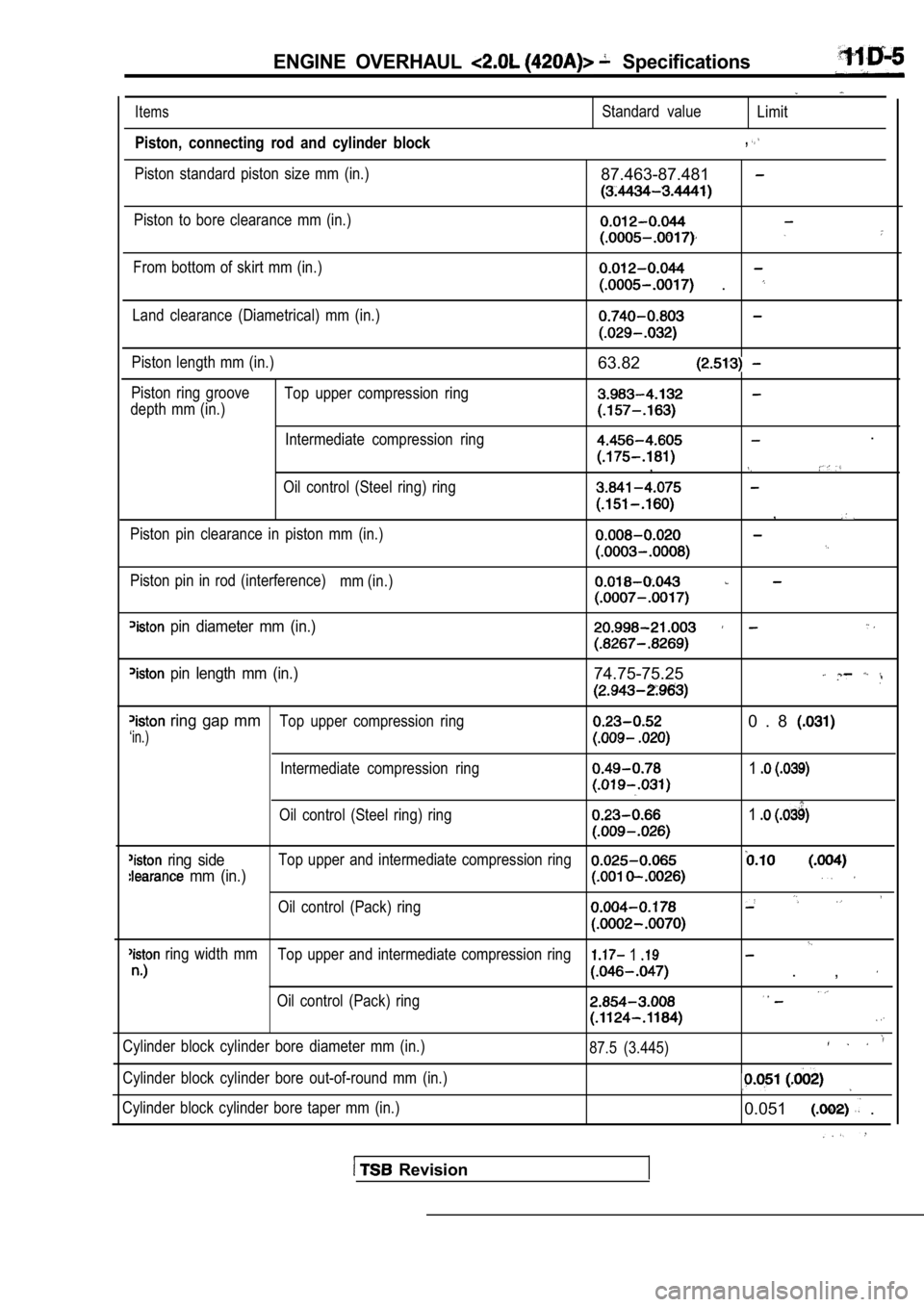
ENGINE OVERHAUL Specifications
Items
Piston, connecting rod and cylinder block
Piston standard piston size mm (in.)
Standard valueLimit
,
87.463-87.481
Piston to bore clearance mm (in.)
From bottom of skirt mm (in.)
.
Land clearance (Diametrical) mm (in.)
Piston length mm (in.)
Piston ring groove Top upper compression ring
depth mm (in.)
Intermediate compression ring
Oil control (Steel ring) ring
Piston pin clearance in piston mm (in.)
Piston pin in rod (interference) mm (in.)
63.82
.
,
,
pin diameter mm (in.)
pin length mm (in.)74.75-75.25
ring gap mmTop upper compression ring0 . 8
‘in.)
Intermediate compression ring1
Oil control (Steel ring) ring1
ring sideTop upper and intermediate compression ring
mm (in.)
Oil control (Pack) ring
ring width mmTop upper and intermediate compression ring 1
. ,
Oil control (Pack) ring
Cylinder block cylinder bore diameter mm (in.)
Cylinder block cylinder bore out-of-round mm (in.)
Cylinder block cylinder bore taper mm (in.) 87.5 (3.445)
0.051 .
Revision
Page 232 of 2103
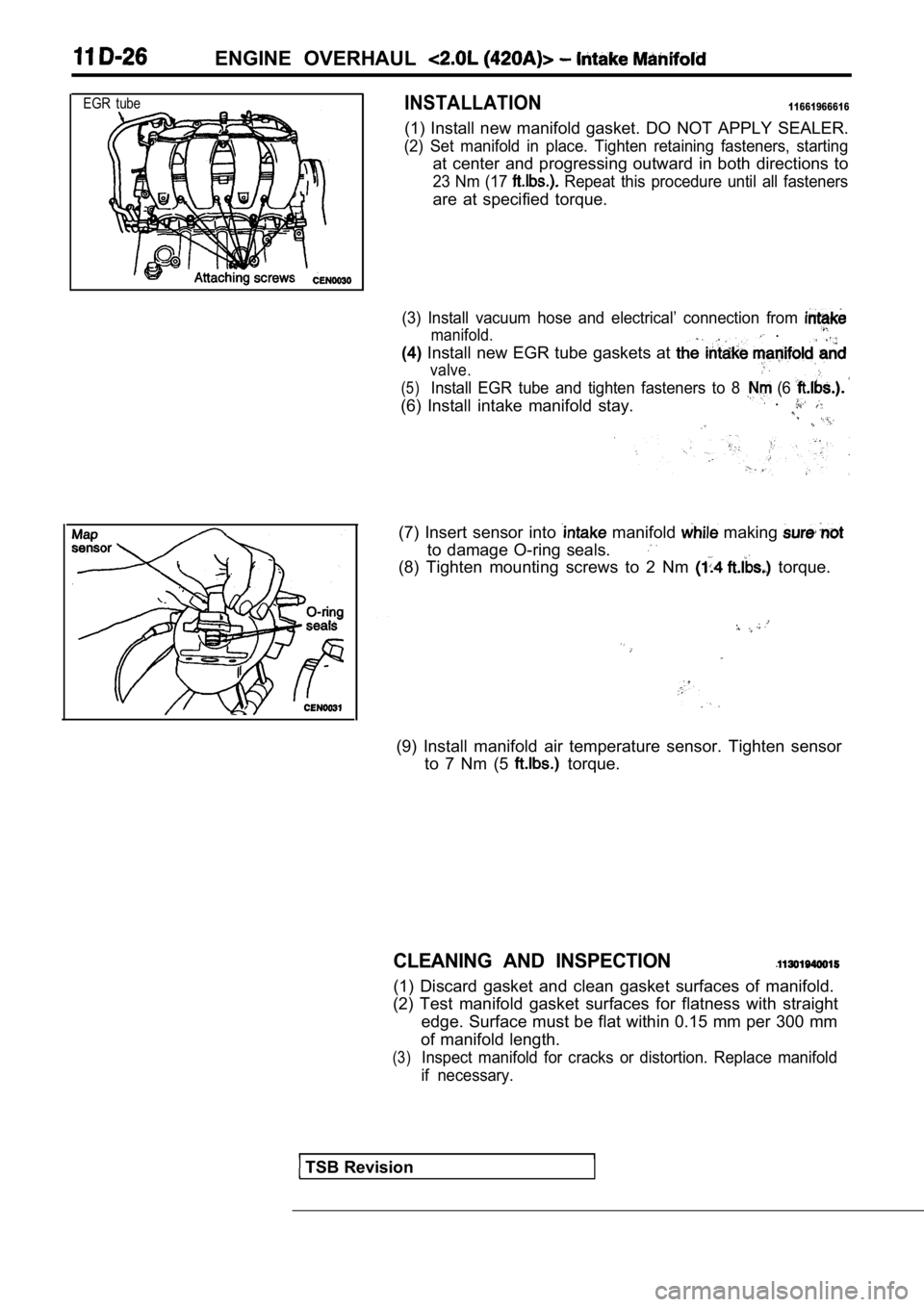
ENGINE OVERHAUL
EGR tubeINSTALLATION11661966616
(1) Install new manifold gasket. DO NOT APPLY SEALER.
(2) Set manifold in place. Tighten retaining fasteners, starting
at center and progressing outward in both direction s to
23 Nm (17 Repeat this procedure until all fasteners
are at specified torque.
(3) Install vacuum hose and electrical’ connection from
manifold. .
(4) Install new EGR tube gaskets at
valve.
(5)Install EGR tube and tighten fasteners to 8 (6
(6) Install intake manifold stay. .
(7) Insert sensor into manifold making
to damage O-ring seals.
(8) Tighten mounting screws to 2 Nm torque.
(9) Install manifold air temperature sensor. Tighte
n sensor
to 7 Nm (5
torque.
CLEANING AND INSPECTION
(1) Discard gasket and clean gasket surfaces of man ifold.
(2) Test manifold gasket surfaces for flatness with straight
edge. Surface must be flat within 0.15 mm per 300 m m
of manifold length.
(3)Inspect manifold for cracks or distortion. Replace manifold
if necessary.
TSB Revision
Page 233 of 2103
ENGINE OVERHAUL Exhaust
EXHAUST MANIFOLD
REMOVAL
(1) Remove oil level gauge.
(2) Remove exhaust manifold. heat shield,
(3) Remove 8 exhaust manifold retaining and
move exhaust manifold.
(1) Install new manifold gasket. DO NOT APPLY-SEALER.
(2) Set exhaust manifold in
Tighten nuts
and bolt, starting at center and
in
both directions to 23
procedure until all fasteners are specified
(3) Install exhaust manifold heat shield, ,
(4) Install oil level gauge.
CLEANING AND INSPECTION
(1) Discard gasket and clean all gasket surfaces of manifolds
and cylinder head.
(2) Test manifold gasket surfaces for flatness with straight
edge. Surface must be flat within 0.15 mm per 300 m m
in. per foot) of manifold length.
(3) Inspect manifolds for cracks or distortion. Rep lace man-
ifold if necessary.
TSB Revision
Page 241 of 2103
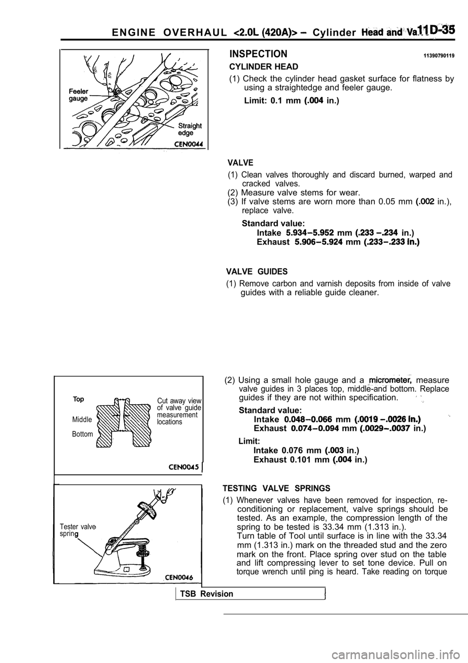
E N G I N E O V E R H A U L Cylinder
INSPECTION11390790119
Middle
Cut away view
of valve guide
measurement
locations
Bottom
Tester valve
sprin
CYLINDER HEAD
(1) Check the cylinder head gasket surface for flat ness by
using a straightedge and feeler gauge.
Limit: 0.1 mm
in.)
VALVE
(1) Clean valves thoroughly and discard burned, war ped and
cracked valves.
(2) Measure valve stems for wear.
(3) If valve stems are worn more than 0.05 mm
in.),
replace valve.
Standard value:
Intake
mm in.)
Exhaust
mm
VALVE GUIDES
(1) Remove carbon and varnish deposits from inside of valve
guides with a reliable guide cleaner.
(2) Using a small hole gauge and a
measure
valve guides in 3 places top, middle-and bottom. Re place
guides if they are not within specification.
Standard value:
Intake
mm
Exhaust mm in.)
Limit:
Intake 0.076 mm in.)
Exhaust 0.101 mm
in.)
TESTING VALVE SPRINGS
(1) Whenever valves have been removed for inspectio n, re-
conditioning or replacement, valve springs should be
tested. As an example, the compression length of th e
spring to be tested is 33.34 mm (1.313 in.).
Turn table of Tool until surface is in line with th e 33.34
mm (1.313 in.) mark on the threaded stud and the ze ro
mark on the front. Place spring over stud on the ta ble
and lift compressing lever to set tone device. Pull on
torque wrench until ping is heard. Take reading on torque
TSB Revision
Page 242 of 2103
1 1 E N G I N E O V E R H A U L Head and
wrench at this instant. Multiply this reading by This
will give the spring load at test length. Fractional measure-
ments are indicated on the table for finer adjustme nts.
Refer to specifications to obtain specified and allow-
able tensions.
Discard the springs that
cations.
Standard value: Free length 46 mm
in.)
Spring tensionV a l v e
m i n
i n . )
Valve open 459-611
mm
(123-137
in.)
(2) inspect each valve spring for squareness with a steel
square and surface plate, test springs from both en ds.
If the spring is more than 1.5 mm in.) out of square,
install a new spring.
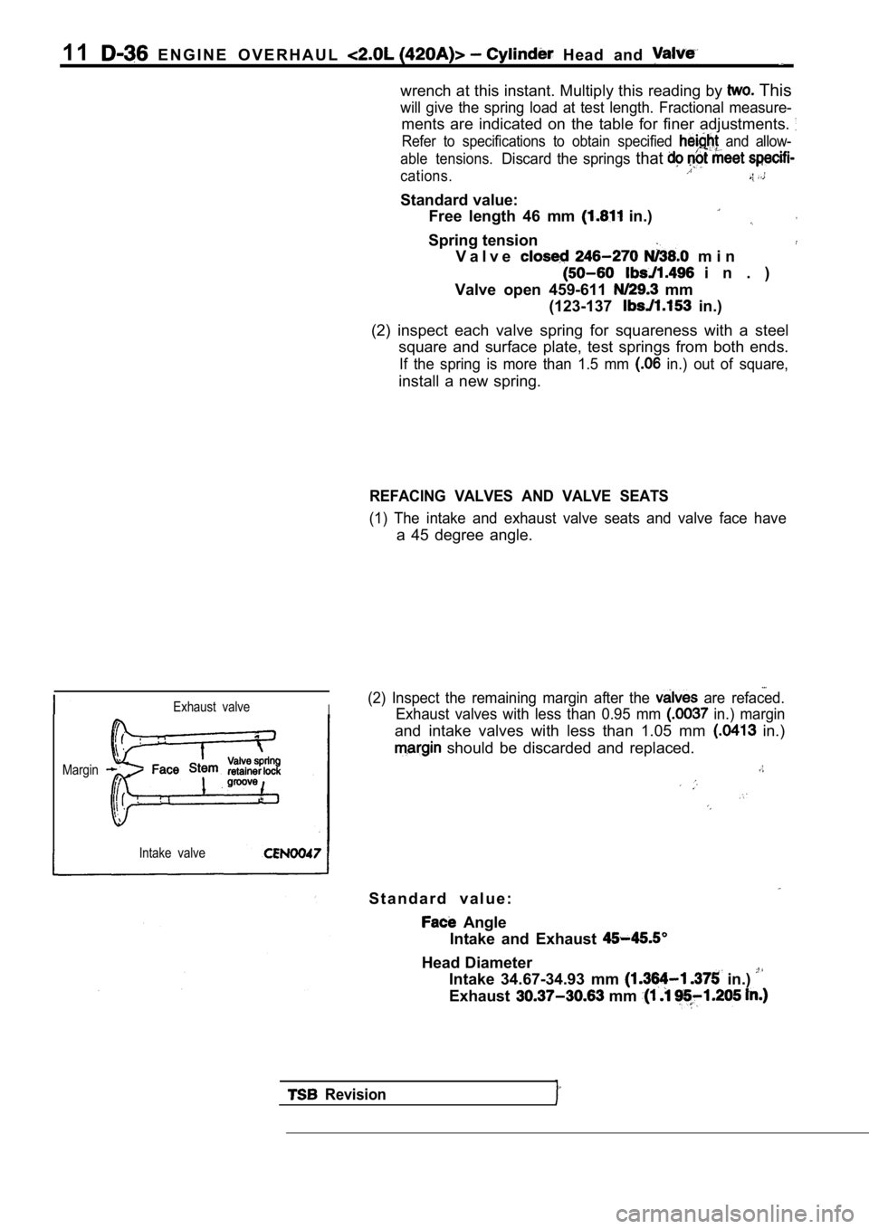
REFACING VALVES AND VALVE SEATS
(1) The intake and exhaust valve seats and valve fa ce have
a 45 degree angle.
Exhaust valveI
Margin
Intake valve
(2) Inspect the remaining margin after the are refaced.
Exhaust valves with less than 0.95 mm
in.) margin
and intake valves with less than 1.05 mm in.)
should be discarded and replaced.
S t a n d a r d v a l u e :
Angle
Intake and Exhaust
Head Diameter Intake 34.67-34.93 mm
in.)
Exhaust mm
Revision
Page 250 of 2103
1E N G I N E - ‘ O i l
Feeler
Outer0rotor
G a s k e tI
(7) Install inner rotor into pump housing. If clear ance between
inner and outer rotors exceeds the limit, replace b oth
rotors.
Limit: mm in.)
(8) Place a straightedge across the face pump
between bolt holes. a feeler mm
in.) or more can be inserted and
straightedge, replace pump
Limit: 0.102 mm ,
(9) Inspect oil pressure relief valve plunger for scoring-and.
free operation in its bore. Small marks may. be rem oved,
with wet or dry sandpaper.
relief valve spring has a free length
60.7 mm (2.39 in.). It should test between -and
when compressed to 40.5 mm (1.60 in.). ,
that fails to meet specifications.
.
oil pressure is and pump is within
inspect for worn engine bearings, or other for
oil pressure loss.
. .
, __ . ,
TSB Revision