Page 1323 of 2103
A U T O M A T I C T R A N S A X L E
OVERHAUL
the end clutch cover tighten the
specified torque.’
End cover mounting
assembly.
with a length mm
in.) and diameter of 1.6 mm in.) on the
rear bearing retainer at the position shown the diagram
and install the outer race.
the differential rear
the to the specified torque:
the bolts, remove the differential
remove the if solder is
repeat steps (51) using the solder with the diameter
of 3 mm.
Differential rear bearing retainer bolts:
35Nm (26
,
the of the
and adjust by selecting a
that will provide the value and
preload..
S t a n d a r d v a l u e :
,,
TSB Revision
Page 1339 of 2103
TRANSAXLE
OVERHAUL -Transaxle
the wave spring, return spring, reaction
brake discs, and brake plates.
the and the rear bearing;
,
__
49
the snap ring-and then remove output flange
assembly.
the output bearing
then remove the output bearing retainer, and outer
a rod 8 mm in.) in diameter and
in.) in length from the the figure
out the rear shaft. ,
Revision
Page 1342 of 2103

A U T O M A T I C T R A N S A X L E
OVERHAUL Transaxle
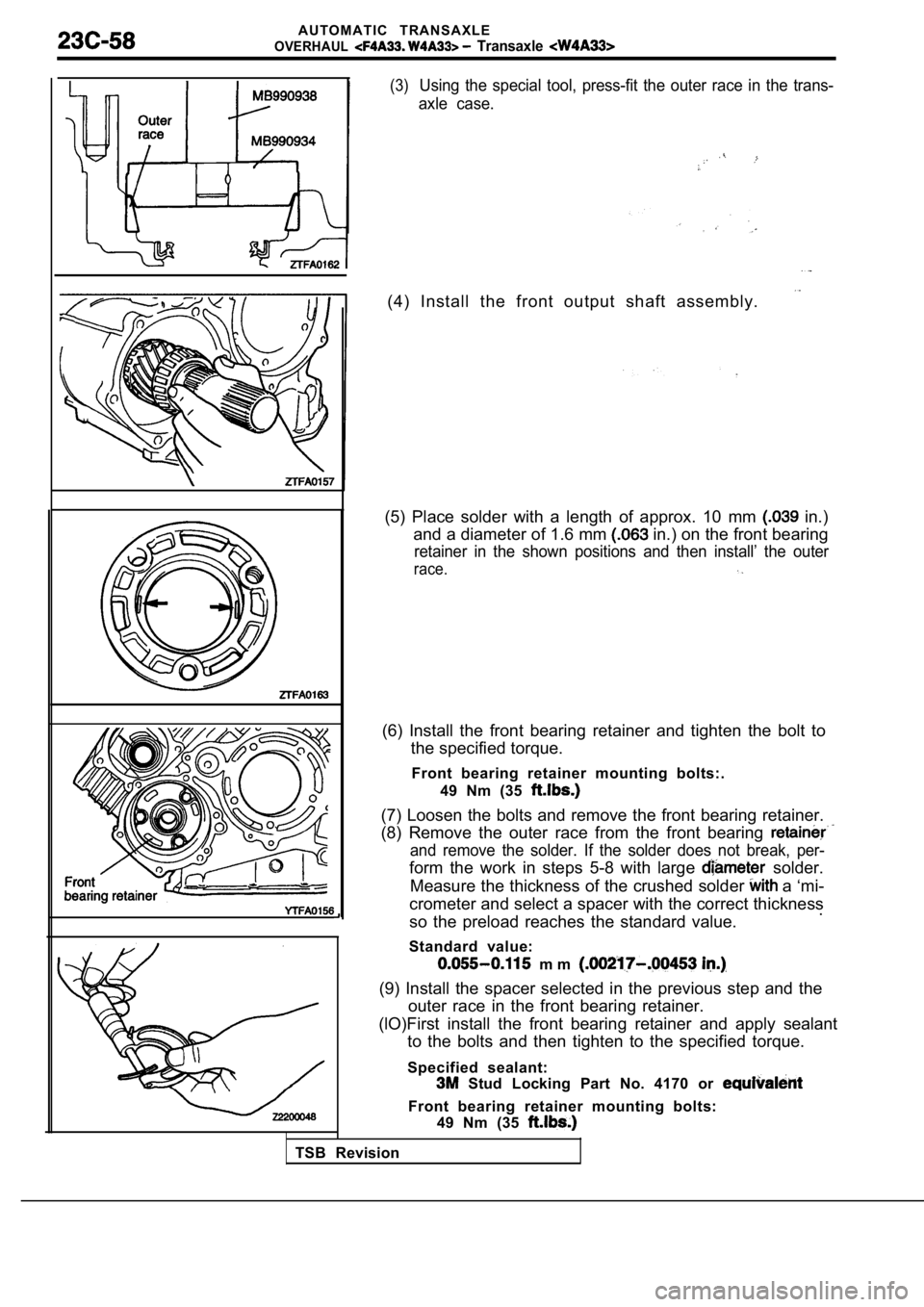
(3)Using the special tool, press-fit the outer race in the trans-
axle case.
(4) Install the front output shaft assembly.
(5) Place solder with a length of approx. 10 mm in.)
and a diameter of 1.6 mm
in.) on the front bearing
retainer in the shown positions and then install’ t he outer
race.
(6) Install the front bearing retainer and tighten the bolt to
the specified torque.
Front bearing retainer mounting bolts:. 49 Nm (35
(7) Loosen the bolts and remove the front bearing r etainer.
(8) Remove the outer race from the front bearing
and remove the solder. If the solder does not break , per-
form the work in steps 5-8 with large solder.
Measure the thickness of the crushed solder
a ‘mi-
crometer and select a spacer with the correct thick ness
so the preload reaches the standard value. .
Standard value:
m m
(9) Install the spacer selected in the previous ste p and the
outer race in the front bearing retainer.
(lO)First install the front bearing retainer and ap ply sealant
to the bolts and then tighten to the specified torq ue.
Specified sealant:
Stud Locking Part No. 4170 or
Front bearing retainer mounting bolts: 49 Nm (35
TSB Revision
Page 1344 of 2103

AUTOMATIC TRANSAXLE
OVERHAUL -Transaxle
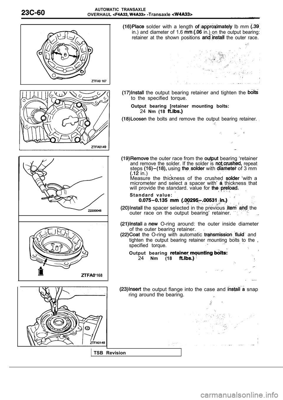
solder with a length lb mm
in.) and diameter of 1.6 in.) on the output bearing:
retainer at the shown positions
the outer race.
167
I
‘168
the output bearing retainer and tighten the
to the specified torque.
Output bearing [retainer mounting bolts: 24Nm (18
the bolts and remove the output bearing retainer.
the outer race from the bearing ‘retainer
and remove the solder. If the solder is repeat
steps using with of 3 mm
in.) ,
Measure the thickness of the crushed ‘with a
micrometer and select a spacer with’
thickness that
will provide the standard. value for
S t a n d a r d v a l u e :
. . .
the spacer selected in the previous the
outer race on the output bearing’ retainer.
a O-ring around: the outer inside diameter
of the outer bearing retainer.
the O-ring with automatic and
tighten the output bearing retainer mounting bolts to the ,
specified torque.
Output bearing
24 Nm (18
the output flange into the case and snap
ring around the bearing.
.
TSB Revision
Page 1354 of 2103
AUTOMATIC TRANSAXLE
OVERHAUL Transaxle
the end clutch cover and tighten the bolts to the
specified torque.
End clutch cover mounting Nm (8
the differential assembly.
solder with a length of approximately 10
in.) and diameter of 1.6 in.) on the differential
rear bearing retainer at the
the outer race.
the differential rear bearing retainer and tighten
the bolts to the specified torque..
the bolts, remove the differential. bearing
retainer and remove the solder. If the crushed,
repeat steps using the solder with the diameter,
of 3 mm.
Differential rear bearing retainer mounting
35 Nm (26
the thickness of the crushed solder with a mi-
crometer and adjust by selecting a spacer with a th ickness
that will provide the standard value for the. end play and
preload.
Standard
m m
TSB RevisionI
Page 1492 of 2103

General Information/Service Specifications/
PROPELLER SHAFT Lubricants/Adhesive
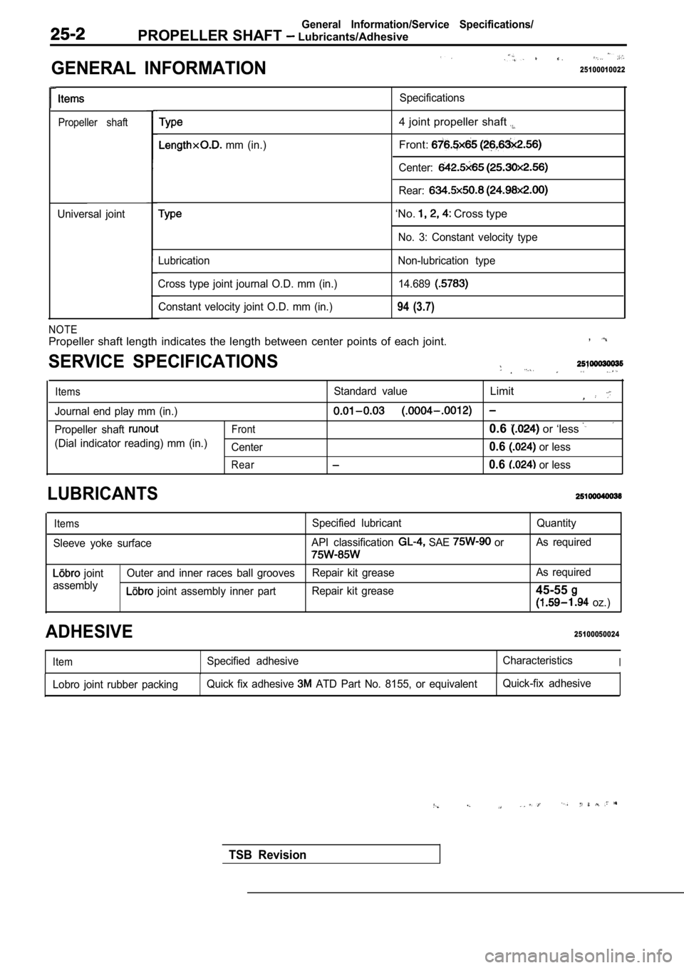
GENERAL INFORMATION
. .
25100010022
Propeller shaft
Universal jointSpecifications
mm (in.)
4 joint propeller shaft
Front:
Center:
Rear:
‘No. Cross type
No. 3: Constant velocity type
Lubrication
Cross type joint journal O.D. mm (in.) Constant velocity joint O.D. mm (in.) Non-lubrication type
14.689
94 (3.7)
NOTE
Propeller shaft length indicates the length between center points of each joint. ,
SERVICE SPECIFICATIONS
ItemsStandard valueLimit
Journal end play mm (in.)
Propeller shaft Front0.6 or ‘less
(Dial indicator reading) mm (in.)
Center0.6 or less
Rear0.6 or less
LUBRICANTS
Items
Sleeve yoke surface Specified lubricant
API classification SAE or
Quantity
As required
joint
assembly Outer and inner races ball grooves
Repair kit grease As required
joint assembly inner part
Repair kit grease45-55
oz.)
25100050024ADHESIVE
ItemSpecified adhesive CharacteristicsI
Lobro joint rubber packingQuick fix adhesive ATD Part No. 8155, or equivalent Quick-fix adhesive
TSB Revision
Page 1506 of 2103

GENERAL INFORMATION
FRONT AXLE General Specification/Lubricants
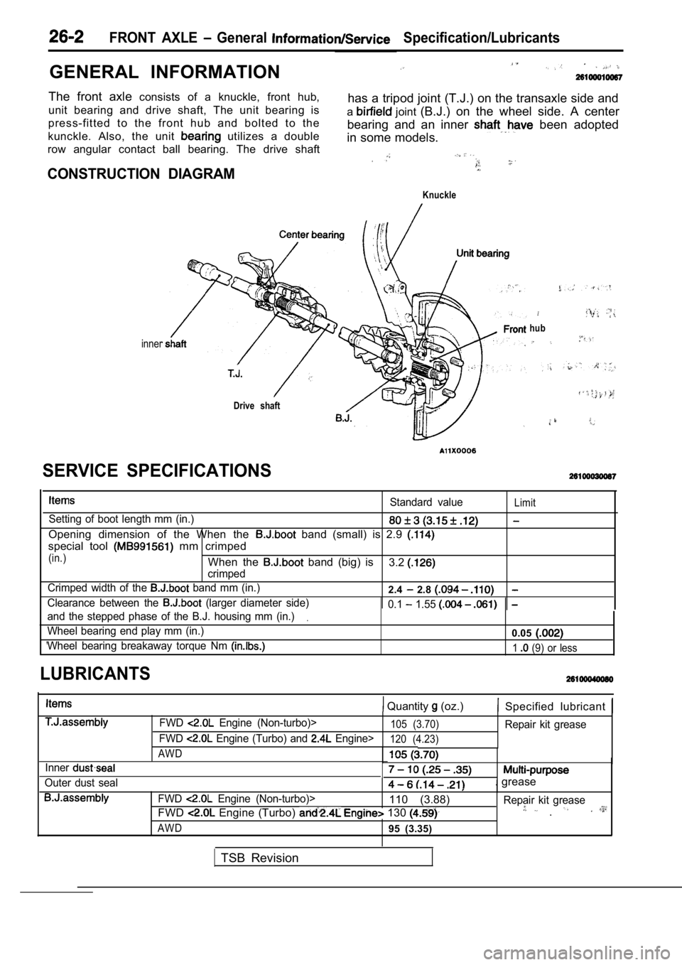
The front axle consists of a knuckle, front hub,
unit bearing and drive shaft, The unit bearing is has a tripod joint (T.J.) on the transaxle side and
press-fitted to the front hub and bolted to the a
joint
(B.J.) on the wheel side. A center
kunckle. Also, the unit
utilizes a double bearing and an inner been adopted
in some models.
row angular contact ball bearing. The drive shaft
CONSTRUCTION DIAGRAM
Knuckle
inner
Drive shaft
hub
Standard valueLimit
Setting of boot length mm (in.)
Opening dimension of the When the band (small) is 2.9
special tool mm crimped
(in.)When the band (big) is
crimped3.2
Crimped width of the band mm (in.)2.4 2.8
Clearance between the (larger diameter side) 0.1 1.55
and the stepped phase of the B.J. housing mm (in.).
Wheel bearing end play mm (in.)0.05
Wheel bearing breakaway torque Nm 1 (9) or less
SERVICE SPECIFICATIONS
LUBRICANTS
Quantity (oz.) Specified lubricant
Inner
Outer dust sealFWD
Engine (Non-turbo)>105 (3.70)Repair kit grease
FWD
Engine (Turbo) and Engine>120 (4.23)
AWD
. grease
FWD Engine (Non-turbo)>110 (3.88) Repair kit grease
FWD Engine (Turbo) 130 .
AWD95 (3.35)
TSB Revision
Page 1600 of 2103
POWER PLANT MOUNT
RemovalPress-fitting
Nut
Bushing A
Inner pipe
Bushing
Inner pipe
RemovalPress-fitting
TSB Revision
Inner pipe
CROSSMEMBER BUSHING
B U S H I N G
(1) Apply soapy water to the contact ‘surface of th
e
when press-fitting the bush. ,
(2) The bush should be press-fitted that’ the inner
projection is at the standard length.
S t a n d a r d
Bushing A: mm in.)
Bushing B:
mm in.)
(1) Use the special tool to drive out and press-fit the
member bushing C. .
.
(2) The bushing should be press-fitted so that the inner pipe
projection is at the standard length.
Standard value (A):
mm in.)
INSPECTION
lCheck the crossmember for cracks or deformation.
lCheck the bushings for cracks or’deterioration.