Page 1602 of 2103

FRONT SUSPENSION General Information
GENERAL INFORMATION
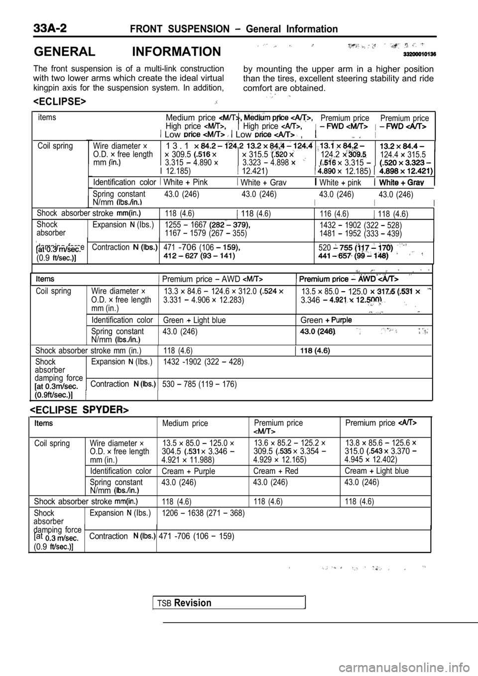
The front suspension is of a multi-link constructionby mounting the upper arm in a higher position
with two lower arms which create the ideal virtual than the tires, excellent steering stability and ride
kingpin axis for the suspension system. In addition ,comfort are obtained.
itemsMedium price
High price
Premium price
I
Premium priceHigh price I Low Low ,I
Coil spring
Wire diameter
O.D. free length
1 3 . 1
309.5 315.5 mm3.315 4.890 3.323 4.898
124.2
3.315
I 12.185) 12.421) 12.185)
Identification color White Pink White GravIWhite pink
124.4 315.5
Spring constant 43.0 (246) 43.0 (246)
I
43.0 (246)N/mmI
43.0 (246)
I
Shock absorberstroke118 (4.6) 118(4.6)116 (4.6) 118 (4.6)
Shock Expansion
(Ibs.)1255 16671432 1902(322 528)
absorber 1167 1579(267355)1481 1952 (333 439)
damping force
Contraction471-706(106520
(0.9
Premium price AWD
Coilspring Wire diameter 13.3 84.6 124.6 312.013.5 85.0 125.0
O.D. free length 3.331 4.906 12.283)3.346
mm (in.)
Identification color Green Light blueGreen
Spring constant43.0 (246)
N/mm
Shock absorber stroke mm (in.)118 (4.6)
ShockExpansion (Ibs.)
1432 -1902 (322 428)
absorber
damping force
Contraction530 785 (119 176)
TSBRevision
Medium price Premium pricePremium price
Coil spring Wire diameter 13.5 85.0 125.0 13.6 85.2 125.2 13.8 85.6 125.6
O.D. free length304.5 3.346 309.5 3.354 315.0 3.370
mm (in.) 4.921 11.988)
4.929 12.165)4.945 12.402)
Identification color Cream
PurpleCream RedCream Light blue
Spring constant 43.0 (246) 43.0 (246) 43.0 (246)
N/mm
Shock absorber stroke 118 (4.6) 118 (4.6) 118 (4.6)
ShockExpansion (Ibs.)
1206 1638 (271 368)
absorber
damping force
[atContraction 471 -706 (106 159)
(0.9
Page 1609 of 2103
FRONT SUSPENSION Shock Absorber
DISASSEMBLY AND, REASSEMBLY
12
9
- -
Disassembly steps
n u t
Upper bushing A 4. Upper bracket assembly
5. Upper spring pad
6. Collar
1 2 3 7 .
7. Upper bushing 8. assembly . . 10. Dust cover
12. Shock
,
DISASSEMBLY SERVICE POINT
SELF-LOCKING NUT REMOVAL
(1) the coil spring using the special tools.
Caution
1. Install the special tools evenly so that the
maximum length will be attained
the
installation range.
2. Do not use an impact wrench to tighten the specia l
tool bolt.
(2) While holding the piston rod, remove the self-locking nut.
Caution
Do not use an impact wrench to the
tool bolt.
TSB Revision
Page 1618 of 2103

REAR SUSPENSION General Information
GENERAL INFORMATION
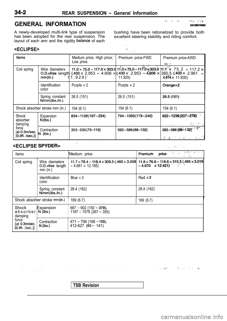
A newly-developed multi-link type of suspensionhas been adopted for the rear suspension. The bushing have been rationalized to provide both
excellent steering stability and riding comfort.
layout of each arm and the rigidity of each
.
Coil spring Medium price, High price,’
Premium price-FWDPremium price-AWD
Low price.Wire diameterx 7 5 . 2 117.2
length 2.953 4.606 2.953 360.5 2.961
1 1 . 9 2 9 ) ’11.929) 11.830)
Identification Purple 2 Purple 2
color
Spring constant 26.5 (151) 26.5 (151)
Shock absorber stroke mm (in.)
154 (6.1)154 (6.1)
154 (6.1)
Shock Expansion
absorber
damping
forceContraction
. . .
“Medium price ,
Wire diameterx
length 4.661 12.185) ,
mm (in.)
Items
Coil spring
TSB Revision
Identification
color Blue 2Red
Spring constant 28.4 (162)
28.4 (162)
Shock absorber stroke 169 (6.7)169 (6.7)
Shock Expansion667 902 (150
a b s o r b e r1187 1579 (267 355)
damping
force
[atContraction471 706 (106
/sec.)]412-627 141)
Page 1631 of 2103
REAR SUSPENSION Shock Absorber
DISASSEMBLY AND REASSEMBLY
Disassembly steps
n u t
Upper bushing A 4. Upper bracket assembly
5. Upper spring pad
6. Upper bushing
22Nm16
6
8
. 10
7.Collar8.Cup assembly9.Dust cover10.Bump rubber11.Coil spring
12. Shock absorber assembly
DISASSEMBLY SERVICE POINTS
SELF-LOCKING NUT REMOVAL
(1)
the coil spring using the special tools.
Caution
1. Install the special tools evenly, and so that th e
maximum length will be attained the
installation range.
2.Do not use an impact wrench to tighten the special
tool bolt.
TSB Revision
Page 1666 of 2103
BASIC BRAKE SYSTEM Master Brake Booster
If the clearance is not within the standard
turn
the
screw to achieve desired length.
‘ I
.
,
TSB Revision
Page 1839 of 2103

BODY Windshield and Window
SlitRear rail
ail weath
window0 0 0 0 4 8 1 1 12. Close the convertible top
quarter window glass enters the slit on the rear ra
il
weatherstrip
when the quarter windows are
Recheck all measurements. Adjustment to any of
adjusting deviceswill affect other settings.
14. Check for sealing quality (wet glass and look f or least
12.7 mm in.) wide seal all glass-to-seal locations.)
15. Install the quarter trim,lower (Refer to GROUP
Trims.)
,
WINDSHIELD AND WINDOW GLASS
GENERAL. .
The windshield and window glass are attached by a urethane-base adhesive, to the window -frame.
This adhesive not only improved glass holding and sealing, but also permi ts use of body openings
having a greater structural strength.
ADHESIVE
Adhesive kit QuantityI
ATD Part No. 8609 SUPER FAST URETHANEOne cartridge
ATD Part No. 8608 SUPER FAST URETHANE PRIMER
As required
RESERVE ITEMS
Items
Wire length)
Adhesive gun
Wiping rags
Sealer
ATD Part or eauivalent
Glass holder
Spacers (Service part)
Window molding (Service part) Dam (Service part)
(Valvoline Oil Company)
,
Applications Quantity
For cutting adhesive Five pieces of wire
0.6 mmx
in. 3.3 ft.)
For adhesive application One
As required
For prevention of water leaks andAs required
gathering after adhesive application
For
As required
T w o
As required
One
As required
As required
TSB Revision
Page 1851 of 2103
BODY Windshield Window
Section A A
QUARTER GLASS ASSEMBLY
REMOVAL
(1) lower the quarter window
(2) the waterproof film.
(3) Disconnect the ball joint of from
quarter window glass through ,
Disconnect connector, from
INSTALLATION SERVICE POINT
QUARTER WINDOW GLASS ASSEMBLY
INSTALLATION
Set the length of the adjusting stud to the dimension shown
in the illustration to make adjustment of the quart er window
glass easier.
INSPECTION
POWERWINDOW MOTOR CHECK
(1) Check that the motor runs smoothly when the bat tery
is connected directly to the motor terminals.
(2) Furthermore, check that the motor operates in r everse
when the terminal connections are switched.
TSB Revision
Page 1944 of 2103

EXTERIOR Windshield and Washer
TROUBLESHOOTING
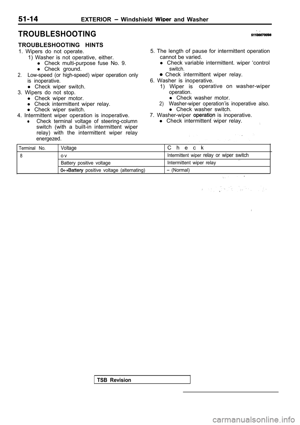
TROUBLESHOOTING HINTS1. Wipers do not operate. 1) Washer is not operative, either.l Check multi-purpose fuse No. 9.
l Check ground.
2.Low-speed (or high-speed) wiper operation only
is inoperative.
l Check wiper switch.
3. Wipers do not stop. l Check wiper motor.
l Check intermittent wiper relay.
l Check wiper switch.
4. Intermittent wiper operation is inoperative.
lCheck terminal voltage of steering-column
switch (with a built-in intermittent wiper relay) with the intermittent wiper relay
energezed.
5. The length of pause for intermittent operation
cannot be varied.
l Check variable intermittent. wiper ‘control
switch.
Check intermittent wiper relay.
6. Washer is inoperative. 1) Wiper is operative on washer-wiper
operation.
l
Check washer motor.
2)Washer-wiper operation’is inoperative also.
l Check washer switch.
7. Washer-wiper
is inoperative.
l Check intermittent wiper relay.
Terminal No.
8
Voltage
o v
Battery positive voltage
positive voltage (alternating)
C h e c k
Intermittent wiper relay or wiper switch
Intermittent wiper relay
(Normal)
TSB Revision