1990 MITSUBISHI SPYDER length
[x] Cancel search: lengthPage 271 of 2103
ENGINEService
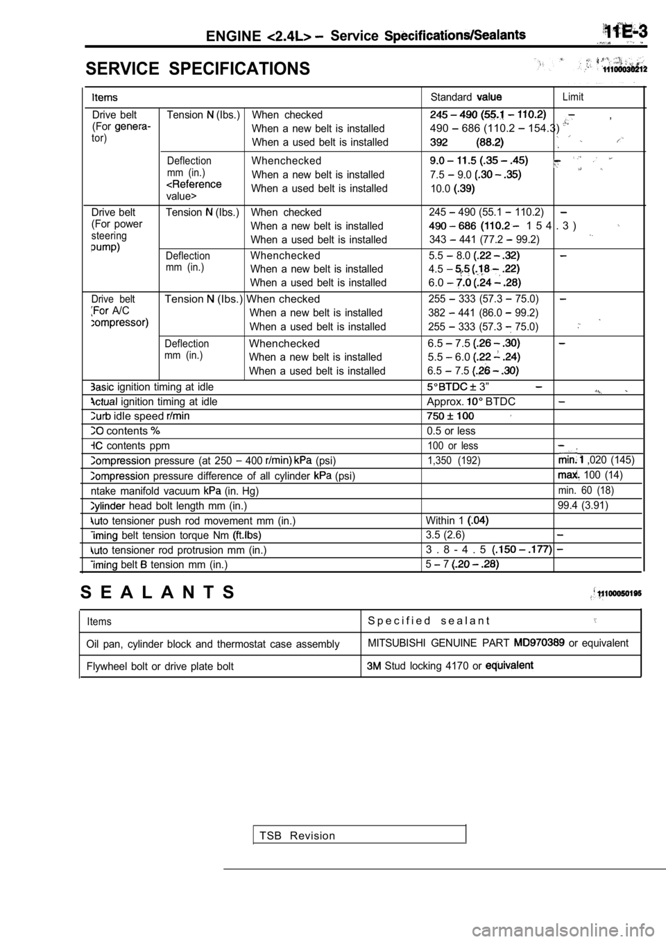
SERVICE SPECIFICATIONS
Drive belt Tension (Ibs.) When checked
(For
When a new belt is installedtor)When a used belt is installed
DeflectionWhenchecked
mm (in.)When a new belt is installed
value> When a used belt is installed
Drive belt Tension
(Ibs.) When checked
(For power When a new belt is installed
steeringWhen a used belt is installed
DeflectionWhenchecked
mm (in.)When a new belt is installed
When a used belt is installed
Drive beltTension (Ibs.) When checked
A/C When a new belt is installed
When a used belt is installed
DeflectionWhenchecked
mm (in.)When a new belt is installed
When a used belt is installed
ignition timing at idle
ignition timing at idle
idle speed
contents
contents ppm
pressure (at 250 400 (psi)
pressure difference of all cylinder (psi)
ntake manifold vacuum
(in. Hg)
head bolt length mm (in.)
tensioner push rod movement mm (in.)
belt tension torque Nm
tensioner rod protrusion mm (in.)
belt tension mm (in.) Standard
Limit
,
490
686 (110.2 154.3)
7.5 9.0
10.0
245 490 (55.1 110.2)
1 5 4 . 3 )
343 441 (77.2 99.2)
5.5 8.0
4.5
6.0
255 333 (57.3 75.0)
382 441 (86.0 99.2)
255
333 (57.3 75.0)
6.5 7.5
5.5 6.0
6.5 7.5
3”
Approx. BTDC
0.5 or less
100 or less
1,350 (192) ,020 (145)
100 (14)
min. 60 (18)
99.4 (3.91)
Within 1
3.5 (2.6)
3 . 8 - 4 . 5
5 7
S E A L A N T S
ItemsS p e c i f i e d s e a l a n t
Oil pan, cylinder block and thermostat case assembl yMITSUBISHI GENUINE PART or equivalent
Flywheel bolt or drive plate bolt
Stud locking 4170 or
TSB Revision
Page 304 of 2103
ENGINE
marks
(22-44
Auto tensioner
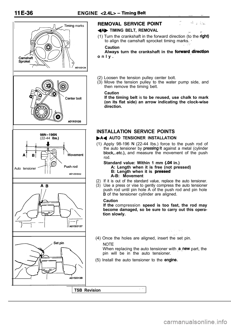
TIMING BELT, REMOVAL
(1) Turn the crankshaft in the forward direction (to the
to align the camshaft sprocket timing marks.
Caution
Always turn the crankshaft in the
o n l y .
(2) Loosen the tension pulley center bolt.
(3) Move the tension pulley to the water pump side, and
then remove the timing belt.
Caution
If the timing belt isto be reused, use chalk to mark
(on its flat side) an arrow indicating the clock-wi se
direction.
INSTALLATION SERVICE POINTS
AUTO TENSIONER INSTALLATION
(1) Apply 98-196 (22-44 Ibs.) force to the push rod of
the auto tensioner by against a metal (cylinder
and measure the movement of the push
rod.
Standard value: Within 1 mm in.)
A: Length when it is free (not pressed) B: Length when it is
A-B: Movement
(2)If it is out of the standard value, replace the aut o tensioner.
(3)Use a press or vise to gently compress the auto ten sioner
push rod until pin hole A of the push rod and pin hole
of the tensioner cylinder are aligned.
Caution
If the compression speed is too fast, the rod may
become damaged, so be sure to carry out this opera-
tion slowly.
(4) Once the holes are aligned, insert the set pin.
NOTE
When replacing the auto tensioner with part, the
pin will be in the auto tensioner.
(5) Install the auto tensioner to the
TSB Revision
Page 306 of 2103
ENGINE Belt
48
Auto tensioner
A
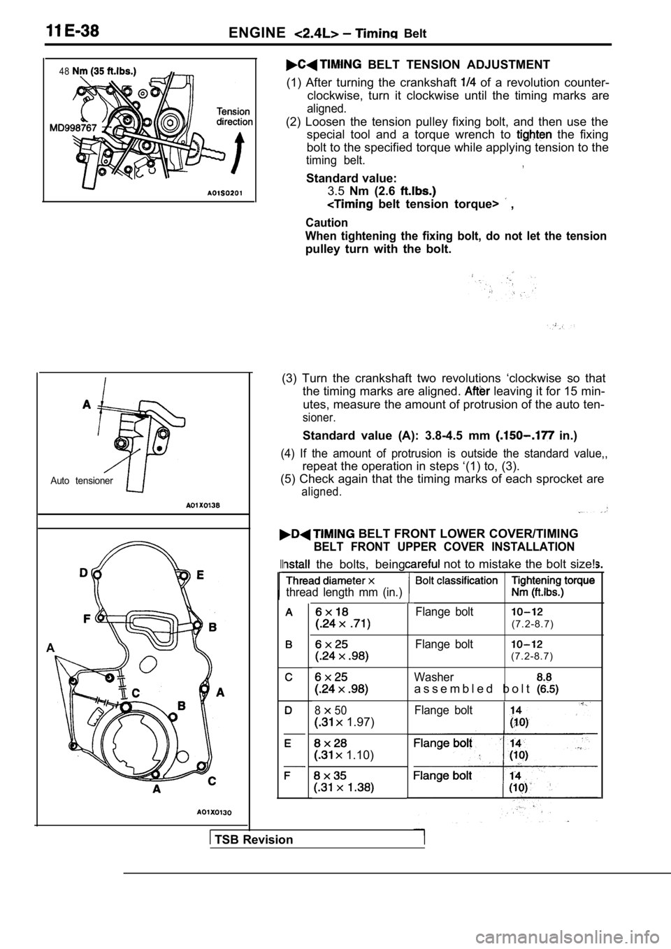
BELT TENSION ADJUSTMENT
(1) After turning the crankshaft
of a revolution counter-
clockwise, turn it clockwise until the timing marks are
aligned.
(2) Loosen the tension pulley fixing bolt, and then use the
special tool and a torque wrench to
the fixing
bolt to the specified torque while applying tension to the
timing belt.,
Standard value:
3.5 Nm (2.6
belt tension torque> ,
Caution
When tightening the fixing bolt, do not let the ten sion
pulley turn with the bolt.
(3) Turn the crankshaft two revolutions ‘clockwise so that
the timing marks are aligned.
leaving it for 15 min-
utes, measure the amount of protrusion of the auto ten-
sioner.
Standard value (A): 3.8-4.5 mm in.)
(4) If the amount of protrusion is outside the standard value,,
repeat the operation in steps ‘(1) to, (3).
(5) Check again that the timing marks of each sproc ket are
aligned.
BELT FRONT LOWER COVER/TIMING
BELT FRONT UPPER COVER INSTALLATION
II the bolts, being
thread length mm (in.)
850
1.97)
1.10)
not to mistake the bolt size!
Flange bolt
(7.2-8.7)
Flange bolt
(7.2-8.7)
Washer
a s s e m b l e d b o l t
Flange bolt
TSB Revision
Page 346 of 2103
ENGINE OVERHAUL Cylinder Head . .
RETAINER LOCK INSTALLATION
valve spring, if excessively compressed, causes the
bottom end of retainer to be, in contact,
and
the stem seal. ,
Identification markI
I4
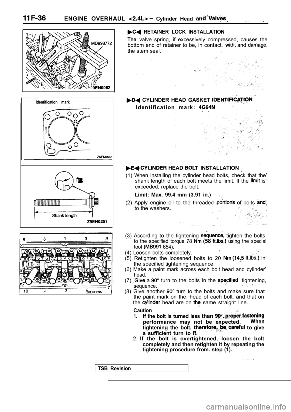
CYLINDER HEAD GASKET
I d e n t i f i c a t i o n m a r k :
HEAD INSTALLATION
(1) When installing the cylinder head bolts, check
that the’
shank length of each bolt meets the limit. If the
is’
exceeded, replace the bolt.
Limit: Max. 99.4 mm (3.91 in.)
(2) Apply engine oil to the threaded of bolts
to the washers.
(3) According to the tightening tighten the bolts
to the specified torque 78 (58 using the special
tool
654).
(4) Loosen bolts completely.
(5) Retighten the loosened bolts to 20 in’
the specified tightening sequence.
(6) Make a paint mark across each bolt head and cyl inder’
head.
(7) a turn to the bolts in the tightening,
sequence.
(8) Give another turn to the bolts and make sure that
the paint mark on the, head of each bolt. and that on
the
head are on same straight line.
Caution
1.If the bolt is turned less than
performance may not be expected.W h e n
tightening the bolt, to give
a sufficient turn to it.
2. If the bolt is overtightened, loosen the bolt
completely and then retighten it by repeating the
tightening procedure from. step (1).
TSB Revision
Page 347 of 2103
E N G I N E O V E R H A U L Cylinder Head and
Valve seatcontact
I
Free
height
INSPECTION
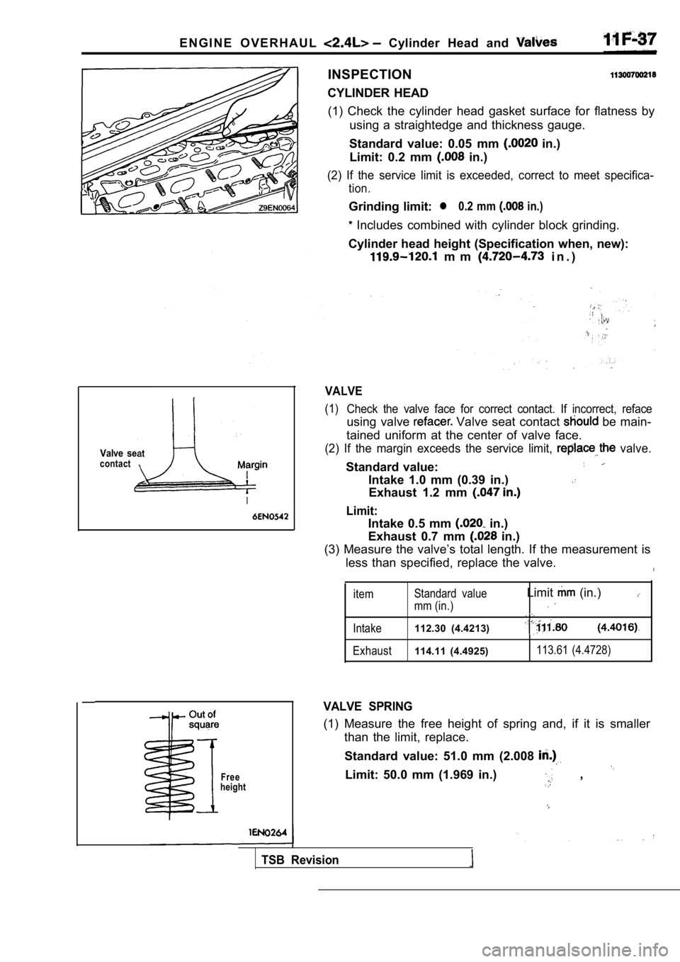
CYLINDER HEAD (1) Check the cylinder head gasket surface for flat ness by
using a straightedge and thickness gauge.
Standard value: 0.05 mm
in.)
Limit: 0.2 mm
in.)
(2) If the service limit is exceeded, correct to me et specifica-
tion.
Grinding limit:l 0.2 mm in.)
Includes combined with cylinder block grinding.
Cylinder head height (Specification when, new):
m m i n . )
VALVE
(1) Check the valve face for correct contact. If incorr ect, reface
using valve Valve seat contact be main-
tained uniform at the center of valve face.
(2) If the margin exceeds the service limit, valve.
Standard value:
Intake 1.0 mm (0.39 in.)
Exhaust 1.2 mm
Limit:
Intake 0.5 mm in.)
Exhaust 0.7 mm
in.)
(3) Measure the valve’s total length. If the measur ement is
less than specified, replace the valve.
item Standard value
mm (in.)
Limit (in.)
Intake112.30 (4.4213)
Exhaust114.11 (4.4925)113.61 (4.4728)
VALVE SPRING
(1) Measure the free height of spring and, if it is
smaller
than the limit, replace.
Standard value: 51.0 mm (2.008
Limit: 50.0 mm (1.969 in.) ,
TSB Revision
Page 355 of 2103
ENGINE OVERHAUL Shaft and Can
Case,
62
Crank pulley side
0
mm bolts
0
Oil pan viewed from lower side
(2) Secure the oil pump driven gear onto the left counterbal-
ance shaft by tightening the flange bolt to specified torque.
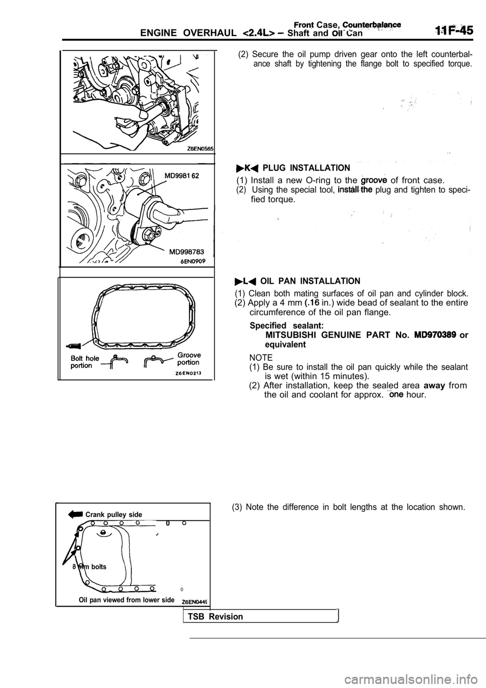
PLUG INSTALLATION
(1) Install a new O-ring to the of front case.
(2)Using the special tool, plug and tighten to speci-
fied torque.
OIL PAN INSTALLATION
(1) Clean both mating surfaces of oil pan and cylin der block.
(2) Apply a 4 mm in.) wide bead of sealant to the entire
circumference of the oil pan flange.
Specified sealant:
MITSUBISHI GENUINE PART No. or
equivalent
NOTE
(1) Be sure to install the oil pan quickly while th e sealant
is wet (within 15 minutes).
(2) After installation, keep the sealed area awayfrom
the oil and coolant for approx.
hour.
(3) Note the difference in bolt lengths at the loca tion shown.
TSB Revision
Page 364 of 2103
11ENGINE OVERHAUL P i s t o n
ylinder No.
CONNECTING ROD CAP INSTALLATION
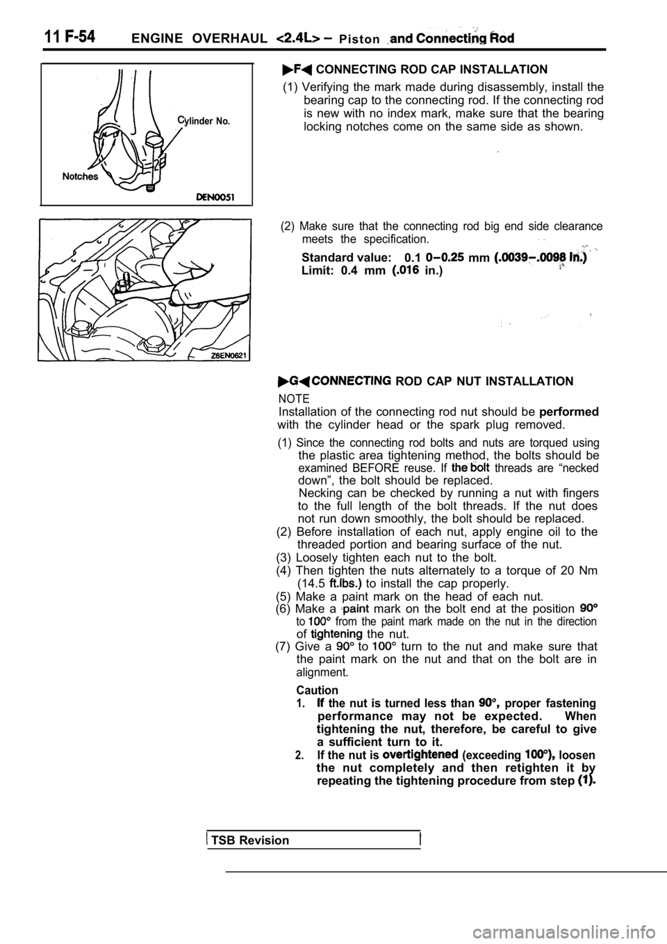
(1) Verifying the mark made during disassembly, ins tall the
bearing cap to the connecting rod. If the connectin g rod
is new with no index mark, make sure that the beari ng
locking notches come on the same side as shown.
(2) Make sure that the connecting rod big end side clearance
meets the specification.
Standard value: 0.1 mm
Limit: 0.4 mm in.)
ROD CAP NUT INSTALLATION
NOTE
Installation of the connecting rod nut should be performed
with the cylinder head or the spark plug removed.
(1) Since the connecting rod bolts and nuts are tor qued using
the plastic area tightening method, the bolts should be
examined BEFORE reuse. If threads are “necked
down”, the bolt should be replaced.
Necking can be checked by running a nut with finger s
to the full length of the bolt threads. If the nut does
not run down smoothly, the bolt should be replaced.
(2) Before installation of each nut, apply engine o il to the
threaded portion and bearing surface of the nut.
(3) Loosely tighten each nut to the bolt.
(4) Then tighten the nuts alternately to a torque o f 20 Nm
(14.5
to install the cap properly.
(5) Make a paint mark on the head of each nut.
(6) Make a
mark on the bolt end at the position
to from the paint mark made on the nut in the directi on
of the nut.
(7) Give a
to turn to the nut and make sure that
the paint mark on the nut and that on the bolt are in
alignment.
Caution
1. the nut is turned less than proper fastening
performance may not be expected.When
tightening the nut, therefore, be careful to give
a sufficient turn to it.
2.If the nut is (exceeding loosen
the nut completely and then retighten it by repeating the tightening procedure from step
TSB Revision
Page 365 of 2103
ENGINE OVERHAUL Piston and Rod
INSPECTION
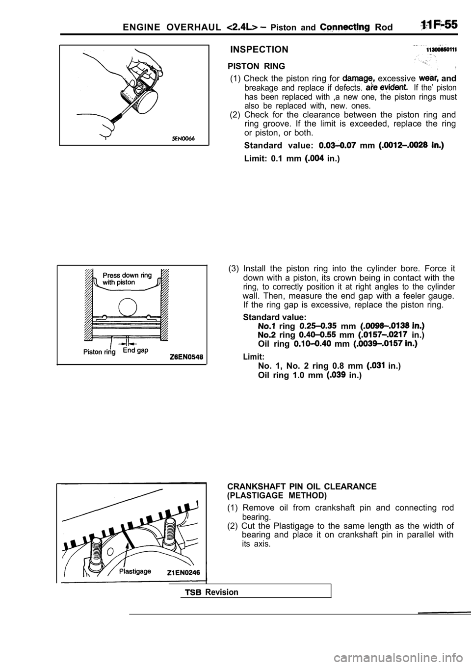
PISTON RING (1) Check the piston ring for
excessive and
breakage and replace if defects. If the’ piston
has been replaced with ,a new one, the piston rings must
also be replaced with, new. ones.
(2) Check for the clearance between the piston ring and
ring groove. If the limit is exceeded, replace the ring
or piston, or both.
Standard value:
mm
Limit: 0.1 mm in.)
(3) Install the piston ring into the cylinder bore. Force it
down with a piston, its crown being in contact with the
ring, to correctly position it at right angles to the cylinder
wall. Then, measure the end gap with a feeler gauge .
If the ring gap is excessive, replace the piston ri ng.
Standard value:
ring mm
ring mm in.)
Oil ring
mm
Limit:
No. 1, No. 2 ring 0.8 mm in.)
Oil ring 1.0 mm
in.)
Revision
CRANKSHAFT PIN OIL CLEARANCE
(PLASTIGAGE METHOD)
(1) Remove oil from crankshaft pin and connecting r od
bearing.
(2) Cut the Plastigage to the same length as the width of
bearing and place it on crankshaft pin in parallel with
its axis.