1990 MITSUBISHI SPYDER bulb
[x] Cancel search: bulbPage 466 of 2103
![MITSUBISHI SPYDER 1990 Service Repair Manual INSPECTION PROCEDURE 3,
T h e c h e c k i n d i c a t o r . l a m p n o t
illuminate right after the ignition switch is turned to the
position. ,
[Comment]l bulbThe PCM ca MITSUBISHI SPYDER 1990 Service Repair Manual INSPECTION PROCEDURE 3,
T h e c h e c k i n d i c a t o r . l a m p n o t
illuminate right after the ignition switch is turned to the
position. ,
[Comment]l bulbThe PCM ca](/manual-img/19/57345/w960_57345-465.png)
INSPECTION PROCEDURE 3,
T h e c h e c k i n d i c a t o r . l a m p n o t
illuminate right after the ignition switch is turned to the
position. ,
[Comment]l bulbThe PCM causes the check engine/malfunction indicator lamp to illuminate for three seconds, l Defective check engine/malfunction immediately after the ignition switch is turned to ON.
If the check engine/malfunction indicator lamp does not illuminate immediately after the ignition llamp circuit of the switch is turned to ON, one of the malfunctions lis
ted at right probably occurred.
NG
10Battery voltage (Refer toCheck the power supply and ignition circuit.
(Refer to I N S P E C T I O N
Measure at the PCM connector,
OK: The check engine/malfunction indicator lamp
NG
Check a burnt-out bulb.
OK
N G Replace
Measure at the combination meter connector
lDisconnect the connector, and measure at the harnes s
side.
lVoltage between 10 and ground (Ignition switch: ON)
OK: Battery positive voltage
OK
Replace the PCM.I
NGCheck the check engine/malfunction indicator power supply circuit. Repair, if necessary.; ,
Check the
OK
Repair
Check trouble symptom.I
Check the harness wire between combination meter an d
PCM connector. Repair, if necessary.
TSB Revision
Page 582 of 2103
![MITSUBISHI SPYDER 1990 Service Repair Manual ENGINE ( T U R B O )
AND ENGINE>
INSPECTION PROCEDURE 3.,
The check engine/malfunction indicator lamp not
nate right after the is turned to the, ON position.
[Comment]
The ECM cau MITSUBISHI SPYDER 1990 Service Repair Manual ENGINE ( T U R B O )
AND ENGINE>
INSPECTION PROCEDURE 3.,
The check engine/malfunction indicator lamp not
nate right after the is turned to the, ON position.
[Comment]
The ECM cau](/manual-img/19/57345/w960_57345-581.png)
ENGINE ( T U R B O )
AND ENGINE>
INSPECTION PROCEDURE 3.,
The check engine/malfunction indicator lamp not
nate right after the is turned to the, ON position.
[Comment]
The ECM causes the check engine/malfunction indicat or lamp to illuminate for five secondsl Defective ,immediately after the ignition switch is turned to ON.lamp circuitIf the check engine/malfunction indicator lamp does not illuminate immediately after the ignition of E C Mswitch is turned to ON, one of the malfunctions listed at right has probably occurred.
SCAN TOOL Date list
16 ECM power supply voltage (Refer to
OK
Measure at the ECM
Check the power supply ignitiori system.,(Refer to INSPECTION PROCEDURE 27.) ,
Check the con- lDisconnect the connector, and measure at the harnes s
Check a burnt-out bulb.
OK
Measure at the combination meter connector lDisconnect the connector, and measure at the harness
side.Check the check engine/malfunction lamp circuit. Repair, if
lVoltage between and ground (Ignition switch: ON)
OK: Battery positive voltage
Check the following Repair
OK
Check trouble symptom.
NG
Check the harness wire between combination meter an d
ECM connector. Repair, if necessary.
TSB Revision
Page 755 of 2103
![MITSUBISHI SPYDER 1990 Service Repair Manual ENGINE AND EMISSION CONTROL Auto-cruise System
INSPECTION PROCEDURE 6
Auto-cruise control cannot be set.
[Comment]A malfunction of the auto-cruise control switch circuit may exist. MITSUBISHI SPYDER 1990 Service Repair Manual ENGINE AND EMISSION CONTROL Auto-cruise System
INSPECTION PROCEDURE 6
Auto-cruise control cannot be set.
[Comment]A malfunction of the auto-cruise control switch circuit may exist.](/manual-img/19/57345/w960_57345-754.png)
ENGINE AND EMISSION CONTROL Auto-cruise System
INSPECTION PROCEDURE 6
Auto-cruise control cannot be set.
[Comment]A malfunction of the auto-cruise control switch circuit may exist.
c a u s e,lMalfunction of the auto-cruise control switch
l M a l f u n c t i o n o f spring.
l Malfunction of the connector.
l
of
Auto-cruise control switch checkN G
Measure at clock spring connector
Disconnect the connector and mea-
* Voltage between terminal (3) and
and 40 Check trouble symptom.
Check the harness between the clockspring and ground. Repair, if necessary.
INSPECTION PROCEDURE 7
Hunting (repeated acceleration and deceleration) oc curs at the
set vehicle speed.
[Comment]
A malfunction of a speed sensor, the speed control servo, or the vacuum supply may be present.
For vehicle speed sensor checkFor input speed sensor or output speed sensor check(Refer to GROUP 54 Combination Meter.)
Speed control servo checkN G
Probable cause
lMalfunction the vehicle speed sensor lMalfunction of the input speed or outputspeed sensor l Malfunction of the l Malfunction of the vacuum supply.
l Malfunction of the PCM.
OK
Vacuum supply check (ReferNG
the PCM.
INSPECTION PROCEDURE 8
When the auto-cruise control main switch is ON, the switch
indicator on the instrument panel does not illumina te.
(However, auto-cruise control is normal.) Probable cause
[Comment]l
Malfunction of the auto-cruise control main
Blown bulb in auto-cruise control main switch.switch.
theau t o - c r u i s e c o n t r o l m a i n s w i t c h .
TSB Revision
Page 756 of 2103

17-16ENGINE AND EMISSION CONTROL Auto-cruise Control System
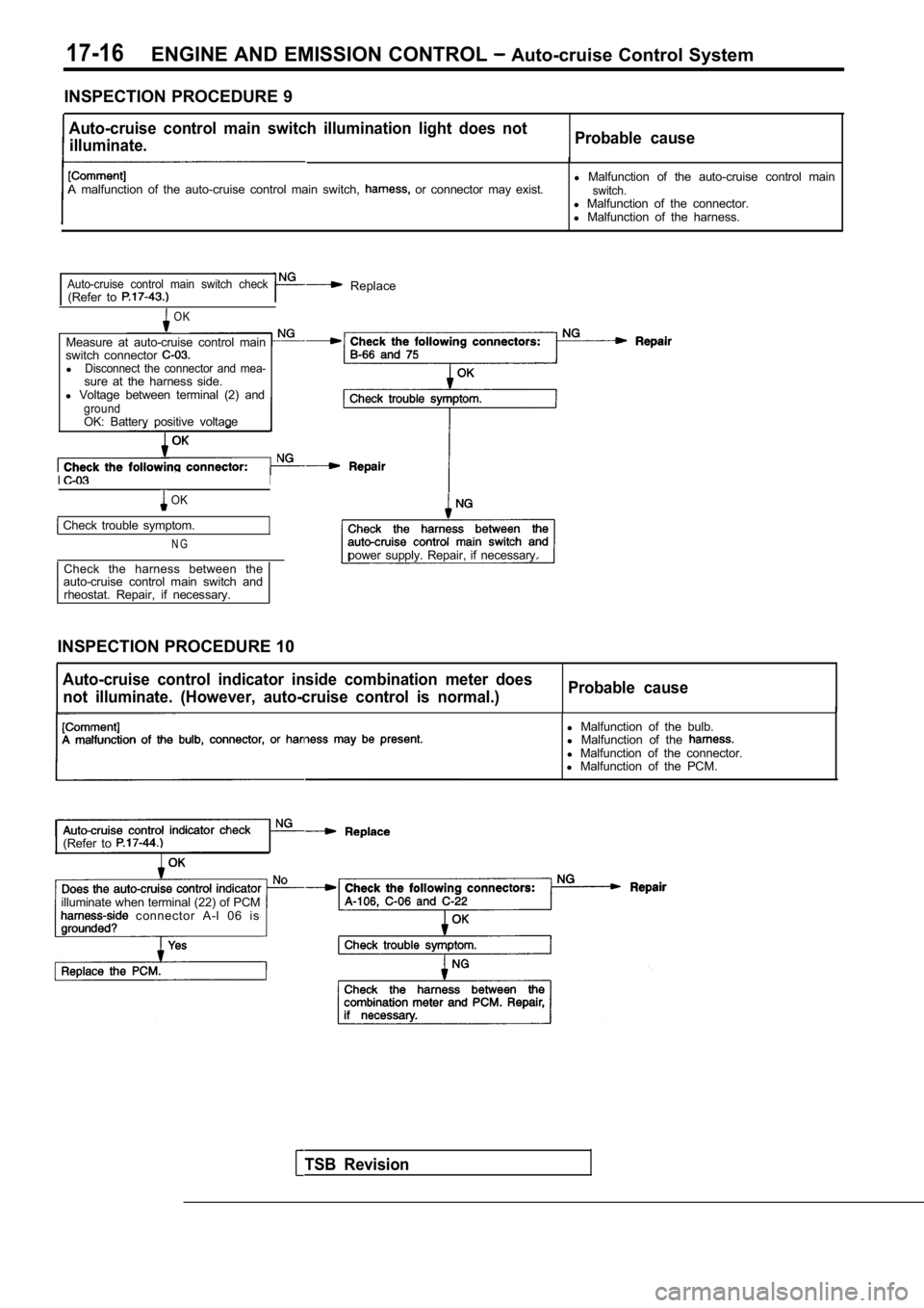
INSPECTION PROCEDURE 9
Auto-cruise control main switch illumination light does not
illuminate. Probable cause
A malfunction of the auto-cruise control main switc
h, or connector may exist.l
Malfunction of the auto-cruise control mainswitch.l Malfunction of the connector.
l Malfunction of the harness.
Auto-cruise control main switch check(Refer to Replace
OK
Measure at auto-cruise control main
switch connector
lDisconnect the connector and mea-sure at the harness side.
l Voltage between terminal (2) and
groundOK: Battery positive voltage
II
OK
Check trouble symptom.
N Gpower supply. Repair, if necessary.
Check the harness between the
auto-cruise control main switch and
rheostat. Repair, if necessary.
INSPECTION PROCEDURE 10
Auto-cruise control indicator inside combination me ter does
not illuminate. (However, auto-cruise control is no rmal.)Probable cause
TSB Revision
l
Malfunction of the bulb.
l Malfunction of the
l Malfunction of the connector.
l Malfunction of the PCM.
(Refer to
illuminate when terminal (22) of PCM connector A-l 06 is
Page 769 of 2103

ENGINE AND EMISSION CONTROL Auto-cruise
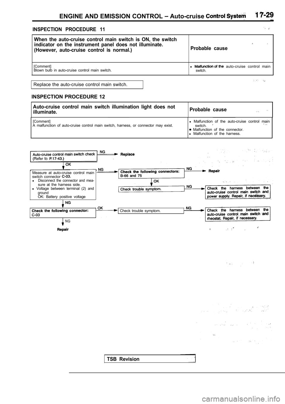
INSPECTION PROCEDURE 11
When the auto-cruise control main switch is ON, the switch
indicator on the instrument panel does not illumina te.
(However, auto-cruise control is normal.) Probable cause
[Comment]l auto-cruise control main
Blown bulb in auto-cruise control main switch.switch.
Replace the auto-cruise control main switch.
INSPECTION PROCEDURE 12
Auto-cruise control main switch illumination light does not
illuminate. Probable cause
[Comment]A malfunction of auto-cruise control main switch, h
arness, or connector may exist.l
Malfunction of the auto-cruise control main
switch. Malfunction of the connector.
l Malfunction of the harness.
(Refer to
Measure at auto-cruise control main
switch connector
lDisconnect the connector and mea-sure at the harness side.
l Voltage between terminal (2) and
groundOK: Battery positive voltage
NG
Check trouble symptom.
TSB Revision
Page 770 of 2103

ENGINE AND EMISSION CONTROL Auto-cruise Control
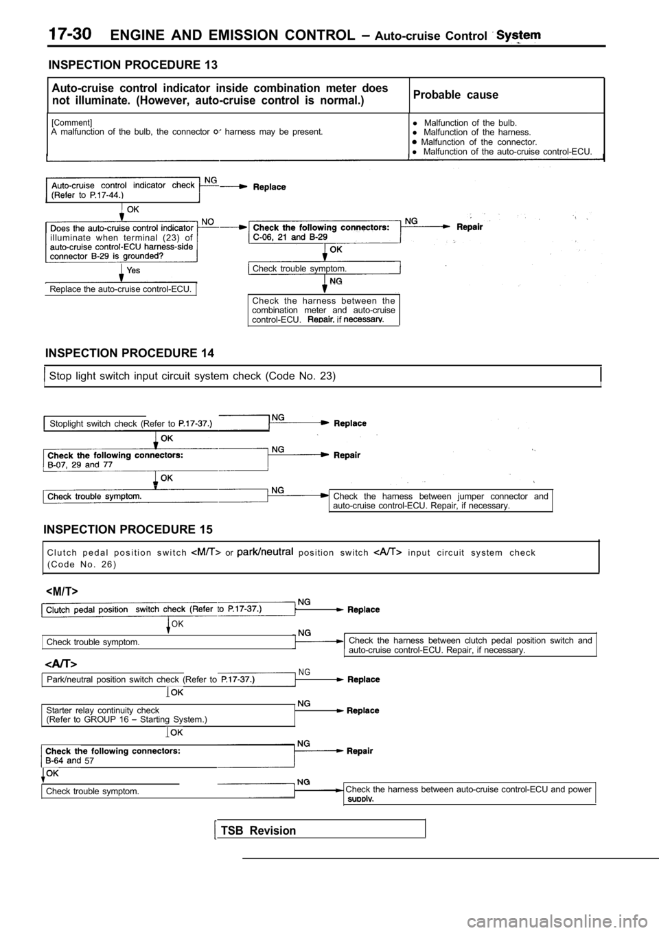
INSPECTION PROCEDURE 13
Auto-cruise control indicator inside combination meter does
not illuminate. (However, auto-cruise control is no rmal.)Probable cause
[Comment]A malfunction of the bulb, the connector harness may be present. l
Malfunction of the bulb.
l Malfunction of the harness. Malfunction of the connector.
l Malfunction of the auto-cruise control-ECU.
to
illuminate when terminal (23) of
Check trouble symptom.
Replace the auto-cruise control-ECU. Check the harness between the
combination meter and auto-cruise
control-ECU.
if
INSPECTION PROCEDURE 14
Stop light switch input circuit system check (Code No. 23)II
Stoplight switch check (Refer to
Check the harness between jumper connector and
auto-cruise control-ECU. Repair, if necessary.
INSPECTION PROCEDURE 15 C l u t c h p e d a l p o s i t i o n s w i t c h
or p o s i t i o n s w i t c h i n p u t c i r c u i t s y s t e m c h e c k
( C o d e N o . 2 6 )
Check trouble symptom.
OK
NG
Check the harness between clutch pedal position swi tch and
auto-cruise control-ECU. Repair, if necessary.
Park/neutral position switch check (Refer to
Starter relay continuity check
(Refer to GROUP 16 Starting System.)
57
Check trouble symptom. Check the harness between auto-cruise control-ECU and power
TSB Revision
Page 1706 of 2103
![MITSUBISHI SPYDER 1990 Service Repair Manual ABS Troubleshooting , ,
INSPECTION PROCEDURE 3When ignition key is turned to “ON” (engine stopped ),
ABS warning light does not illuminate
[Comment]When power is supplied to the MITSUBISHI SPYDER 1990 Service Repair Manual ABS Troubleshooting , ,
INSPECTION PROCEDURE 3When ignition key is turned to “ON” (engine stopped ),
ABS warning light does not illuminate
[Comment]When power is supplied to the](/manual-img/19/57345/w960_57345-1705.png)
ABS Troubleshooting , ,
INSPECTION PROCEDURE 3When ignition key is turned to “ON” (engine stopped ),
ABS warning light does not illuminate
[Comment]When power is supplied to the ABS-ECU, the valve relay changes from to ON by the initial check, and thus even if there is a problem with the circuit between
ABS light and ABS-ECU, the light will illuminate once when the valve relay
is OFF.
Accordingly, the cause of the light not illuminatin g is probably an open circuit in the
light power circuit, a blown light bulb, or an open circuit in both the circuit between
the ABS
light and the ABS-ECU and the circuit between the ABS light and the ABS valve relay.When other lights also do not illuminate, the cause is probably a blown fuse.
Measure at combination meter connector
l Disconnect the connector and mea-
sure at the harness side.
l Ignition Switch ON
lVoltage between terminal 10 and body
OK Battery positive voltage Check trouble symptoms
Measure at combination meter connector
sure at the combination meter side.
l Continuitv between terminals
R e p l a c e t h e
OK Continuity ,
OK
Check the harnesses between the ABS valve relay and the combination meter,
a n d b e t w e e n t h e A B S - E C U a n d
combination meter (common section).
if necessary.
INSPECTION PROCEDURE 4
TSB Revision.
Even after the engine is started, the ABS Warning l ight ,remains illuminated.. .
[Comment]There is probably a short in the ABS warning light illumination circuit.l Malfunction of combination meterl Malfunction of ABS valve relayl Malfunction of ABS-ECU. ,
NOTE
This trouble symptom is limited to cases where comm unication with the scan tool is’
is normal) and the diagnostic trouble code is a normal diagnostic trouble code..YESDisconnect the ABS-ECU connector Does the light remain illuminated?
NO
Short circuit inside the combination or in the harnessbetween the meter and
Replace the ABS-ECU.
Page 1745 of 2103
![MITSUBISHI SPYDER 1990 Service Repair Manual ABS Troubleshooting
INSPECTION PROCEDURE 3
ignition key is turned to “ON’? (engine stopped),ProbableABS warning light does not illuminate
[Comment]When power is supplied to the ABS- MITSUBISHI SPYDER 1990 Service Repair Manual ABS Troubleshooting
INSPECTION PROCEDURE 3
ignition key is turned to “ON’? (engine stopped),ProbableABS warning light does not illuminate
[Comment]When power is supplied to the ABS-](/manual-img/19/57345/w960_57345-1744.png)
ABS Troubleshooting
INSPECTION PROCEDURE 3
ignition key is turned to “ON’? (engine stopped),ProbableABS warning light does not illuminate
[Comment]When power is supplied to the ABS-ECU, the valve relay changes from to OFF ON by the initial check, and thus even if there is a problem with the circuit betweenABS warning light and ABS-ECU, the light will illum inate once when the valve relayis OFF.Accordingly, the cause of the light not illuminating is probably an open circuit in the
light power circuit, a blown light bulb, or an open circuit in both the circuit between
the ABS
liaht and the ABS-ECU and the circuit between the ABS
l Blown fuselBurntout light. bulblMalfunction of wiring. or connector
.
light and the relay.When other lights also do not illuminate, the cause is probab ly a blown fuse.
N GNG ,
Measure at combination meter connector Checkl and l Disconnect the connector and mea-
l Disconnect the connector and mea-
sure atthe combination meter side.
l Continuitv between terminals
OK Continuity
OK
Not
Replace combination meter.
, Check the harnesses between the valve relay and the combination meter,
a n d b e t w e e n t h e A B S - E C U a n d
combination meter (common section).
Repair, if necessary.
INSPECTION PROCEDURE 4
Even after the engine is started, the ABS warning l ight Probable cause ,
remains illuminated.
[Comment]There is probably a short in the ABS light illumination l Malfunction of meter
l Malfunction of valve relay
l Malfunction of ABS-ECU
l Malfunction of wiring
NOTE
This trouble symptom is limited to cases where comm unication with the scan tool is
supply is normal) and the diagnostic trouble code is a normal diagnostic trouble code.
Disconnect the ABS-ECU connector Short circuit inside the combination meter or in the Does the ABS warning light remain illuminated? between the combination meter and the ABS-ECU.
NO
Replace the ABS-ECU.
TSB Revision