Page 576 of 2103
![MITSUBISHI SPYDER 1990 Service Repair Manual (TURBO)
AND ENGINE> Troubleshooting
Code No. Generator Terminal Circuit Malfunction
[Comment]
Background
lWhen the generator field coil is controlled, the generator terminal inpu MITSUBISHI SPYDER 1990 Service Repair Manual (TURBO)
AND ENGINE> Troubleshooting
Code No. Generator Terminal Circuit Malfunction
[Comment]
Background
lWhen the generator field coil is controlled, the generator terminal inpu](/manual-img/19/57345/w960_57345-575.png)
(TURBO)
AND ENGINE> Troubleshooting
Code No. Generator Terminal Circuit Malfunction
[Comment]
Background
lWhen the generator field coil is controlled, the generator terminal inputs a signal to
the engine control module.
lThe engine control module detects the generator out put with the input signal, and controlsthe idle air control motor according to the generator output.
Check Area
l Engine speed is higher than 50
Judgement CriterialInput voltage from the generator terminal has continued to be not lower than 4.5 for 20 sec.
Measure at the generator connector
l Connect the connector.
l Voltage between 4 and ground
Engine: Idle
Radiator fan: stopped
Headlight: off
on
Stop Lamp: off on
Rear defogger switch: off on
OK: voltage drops
NG
Measure at the generator connector lDisconnect the connector, and measure at the harnes s side.
l Voltage between 4 and ground (Ignition switch: ON)
O K :
Probable cause
lOpen circuit in generator terminal circuitl Enginecontrol module failed
,
Replace the ECM.
,
. ,
Check trouble symptom.
NG
NG
Repairbetween theECMand the
OK
connector:
NG Repair
OK
Check trouble symptom. generator
NG
Check the NG Repair Replace the ECM.I
TSB Revision
Replace the generator.1
Code No. Serial Communication Link Malfunction
Probable cause
(with
[Comment]l Automatic transaxle control system Backgroundl Open or short circuit in communication linelThe engine control module receives message signals from the transaxle control modulebetween engine module and transaxlevia the communication line. control module, or poor connector contactlThe engine control module monitors abnormalities in message signals resulting froml
Transaxle control module failed.
a broken communication line or transaxle control mo dule problems.l Engine control module failed.
Check Areal 2 seconds or more have passed since starting was co mpleted.
Judgement CriterialAbnormality in communication line (TCM to ECM) with transaxle control module l Problem with transaxle control module (TCM).
Page 596 of 2103
ENGINE (‘TURBO)
AND ENGINE>
INSPECTION PROCEDURE 23
,
Generator output voltage is low (approx.
[Comment]
The cause may be a malfunction of the generator or one of the problems listed at right.l M a l f u n c t i o n o f c h a r g i n g s y s t e m . l Short harness between t e r m i n a l l Malfunction of the ECM.
OK Check the generator.
,
,. . ,
1
Measure at the generator connector l Connect the connector.
l Voltage between and ground
Engine: idle
Radiator fan: stopped
Headlight: off
on
Stop lamp: off on
Check the following
Check the harness wire between generator and ECM co nnector.
Repair, if necessary.
TSB Revision
Page 605 of 2103
ENGINE (TURBO)
AND
INSPECTION PROCEDURE 33
Fan motor relay system (Radiator fan, A/C condenser fan)Probable cause
[Comment]l Malfunction of fan motor relay
The fan motor relay is controlled by the power tran sistor inside the ECM turning ON and OFF.l Malfunction of fan motorImproper connector open shortclrcuitedl Malfunction of the ECM
Disconnect the connector, and measure at the harnes s
Voltage between 20 and ground, and 21 and ground
l Shortcircuit between 20 and ground (Ignition switch :
Check the Repair
O K
Check trouble symptom.
OK: Radiator fan and condenser fan rotate at highspeed.l Shortcircuit between 21 and ground (Ignition switch :
OK: Radiator fan and condenser fan rotate at lowspeed.
l Check the radiator fan circuit
l Check the condenser fan circuit.
TSB RevisionI
Page 624 of 2103

ENGINE (TURBO)
AND
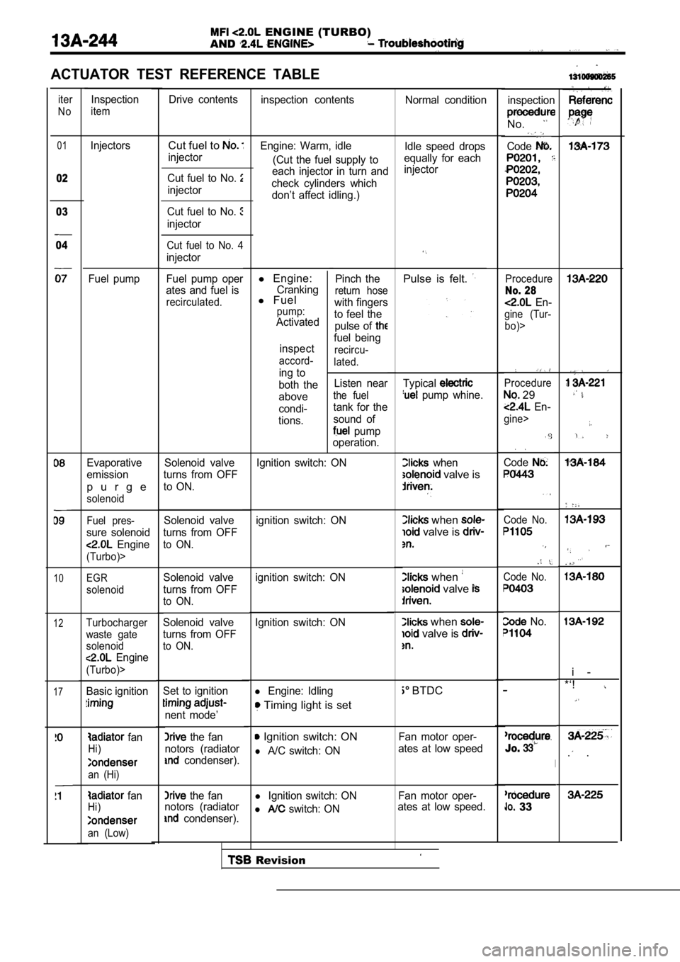
ACTUATOR TEST REFERENCE TABLE
iter
NoDrive contents inspection contents Normal condition
Inspection
iteminspection
No.
Code01
02
Cut fuel to
injector Idle speed drops
equally for each
injector
Engine: Warm, idle
(Cut the fuel supply to
each injector in turn and
check cylinders which don’t affect idling.)
l Engine:Crankingl Fuelpump:Activated
inspect
accord-
ing to
both the
above
condi-
tions. Pinch the
return hose
with fingers
to feel the pulse of
fuel being
recircu-
lated.
Listen near
the fuel
tank for the
sound of
pump
operation.
Injectors
Fuel pump Cut fuel to No.
injector
03
04
Cut fuel to No.
injector
Cut fuel to No. 4
injector
Fuel pump oper
ates and fuel is
recirculated.
Pulse is felt. Procedure
No. 28
En-
gine (Tur-
bo)>
Typical
pump whine.
when
valve is
Procedure
29
En-
gine>
Code
when
valve is
when
valve
Code No.
Code No.
when
valve is
No.
BTDC
Fan motor oper-
ates at low speed
Jo.
l Ignition switch: ON Fan motor oper-
l switch: ON ates at low speed. 33
Evaporative
emission
p u r g e
solenoid
Solenoid valve
turns from OFF
to ON.
. .
i -
*‘!
. .
Ignition switch: ON
Fuel pres-
sure solenoid
Engine
(Turbo)>
ignition switch: ON
Solenoid valve
turns from OFF
to ON.
10EGR
solenoid
ignition switch: ON
Solenoid valve
turns from OFF
to ON.
Solenoid valve
turns from OFF
to ON.
12Ignition switch: ONTurbocharger
waste gate
solenoid
Engine
(Turbo)>
Basic ignitionl Engine: Idling
Timing light is set
17Set to ignition
nent mode’
the fan
notors (radiator
condenser).
Ignition switch: ON
l A/C switch: ON
fan
Hi)
an (Hi)
the fan
notors (radiator
condenser).
fanHi)
an (Low)
Revision
Page 627 of 2103

ENGINE (TURBO)
AND ENGINE>
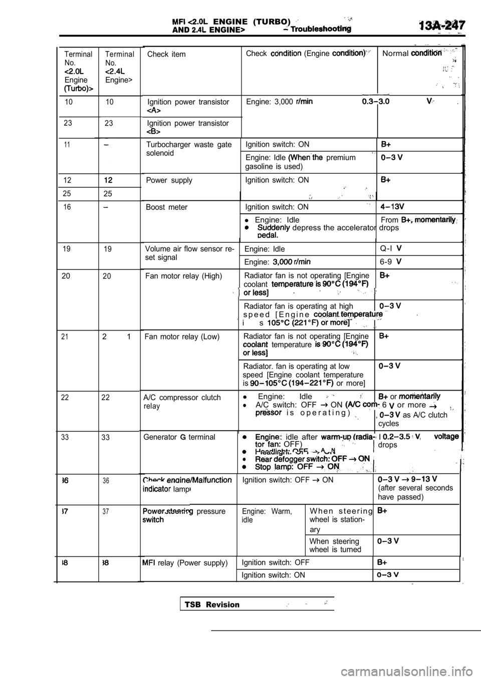
Check itemIgnition power transistorCheck (Engine Normal
Engine: 3,000 .
Ignition power transistor
Terminal No.
Engine
Terminal
No.
Engine>
10 10
23 23
11
12
Turbocharger waste gate Ignition switch: ON
solenoid
Engine: Idle premium
gasoline is used)
Power supply Ignition switch: ON
2525
Boost meter
Ignition switch: ON
l Engine: IdleFrom depress the accelerator drops
16
19
19Volume air flow sensor re- Engine: IdleQ - l
set signal
Engine:6-9
Fan motor relay (High)Radiator fan is not operating [Engine
coolant
2020
21
22
33
.
Radiator fan is operating at high
s p e e d [ E n g i n e
i s
Fan motor relay (Low)Radiator fan is not operating [Engine temperature
Radiator. fan is operating at low
speed [Engine coolant temperature
is
or more]
A/C compressor clutch
l Engine: Idle or
relaylA/C switch: OFF ON 6 or more i s o p e r a t i n g ) , as A/C clutch
cycles
2 1
22
33
ine: idle after I OFF) . . A Ndrops
II. .
Generator terminal
l
36Ignition switch: OFF ON
lamp(after several seconds
have passed)
pressureEngine: Warm,W h e n s t e e r i n g
idlewheel is station-
ary
When steering
wheel is turned
37
relay (Power supply) Ignition switch: OFF
Ignition switch: ON
TSB Revision
Page 691 of 2103

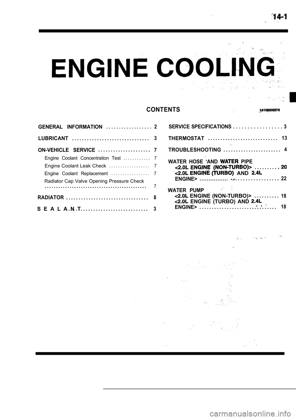
CONTENTS
GENERAL INFORMATION. . . . . . . . . . . . . . . . . .2SERVICE SPECIFICATIONS . . . . . . . . . . . . . . . . . 3
LUBRICANT3THERMOSTAT. . . . . . . . . . . . . . . . . . . . . . . . . . . .13. . . . . . . . . . . . . . . . . . . . . . . . . . . . . . .
ON-VEHICLE SERVICE. . . . . . . . . . . . . . . . . . . . .7TROUBLESHOOTING. . . . . . . . . . . . . . . . . . . . . . .4
Engine Coolant Concentration Test. . . . . . . . . . . .7.
Engine Coolant Leak Check . . . . . . . . . . . . . . . . . .
7WATER HOSE ‘AND PIPE
. . . . . . . . .
Engine Coolant Replacement. . . . . . . . . . . . . . . . .7 AND
Radiator Cap Valve Opening Pressure CheckENGINE>. . . . . . . . . . . . . . . .. . . . . . . . . . . . . . . . . .22
. . . . . . . . . . . . . . . . . . . . . . . . . . . . . . . . . . . . . . . . . . . . .7WATER PUMP
RADIATOR. . . . . . . . . .18. . . . . . . . . . . . . . . . . . . . . . . . . . . . . . . . .8 ENGINE (NON-TURBO)>
ENGINE (TURBO) AND , , S E A L A N T
. . . . . . . . . . . . . . . . . . . . . . . . . . . . . . . . . .3ENGINE>. . . . . . . . . . . . . . . . . . . . . . . . . . . . . . .18
Page 692 of 2103
14-2ENGINE COOLING General Information
GENERAL INFORMATION , ,
The cooling system is designed to keep every partthat the heat absorbed by the coolant may be of the engine at appropriate temperature in diated into the air.
er condition the engine may be operated.
The cooling of the water-cooled, pressureThe water pump is of the centrifugal type and is
driven by the
the
forced circulation type in which the water pump crankshaft. .
pressurizes coolant and circulates it throughout th e
engine: If the coolant temperature exceeds the
scribed temperature, the thermostat opens to circu-
late the coolant through the radiator as well so
and is cooled the
CONSTRUCTION DIAGRAM
Engine (Non-turbo)>
Radiator
Radi
.
oil cooler hose and pipe
Engine (Turbo)>
Radiator fan assembly
(Air cooled) oil cooler hose and pipetank
TSB Revision
Page 693 of 2103
G e n e r a l
ENGINE COOLING
Engine>
Radiator fan assemblyReserve tank
(Airoilcooler
cooled) oil cooler hose and pipe
SERVICE SPECIFICATIONS
ItemsStandard valueLimit
ThermostatValve opening temperature of Engine (Non-turbo)90.5 (195) thermostat Engine (Turbo) and Engine 82 (180)
Full-opening temperature of Engine (Non-turbo)
102 (216)
thermostat
Engine (Turbo) and Engine95 (203),
Radiator cap valve opening pressure (psi) Engine (Non-turbo)9 4 - 1 2 2 ( 1 4 - 1 8 )
Engine (Turbo) and Engine
LUBRICANT
ItemQuantity
Engine coolant HIGH QUALITY ETHYLENE GLYCOL ANTIFREE ZE COOLANT7.0 (7.4)
SEALANT
ItemSpecified sealant,
Thermostat case Engine (Turbo) and Engine>
Mitsubishi Genuine Parts No. or equivalent:
TSB Revision