1990 MITSUBISHI SPYDER radiator
[x] Cancel search: radiatorPage 1175 of 2103
AUTOMATIC TRANSAXLE. .
ENGINE Service
Loud metallic noises coming from indicate loose
parts or internal damage. Remove the
from
the
area and check for a cracked torque converter
flex plate or its bolts.
If the flex plate and bolts are ok, and there is st ill noise coming
from the torque converter, the torque converter may be defec-
t i v e a n d m u s t b e r e p l a c e d .
Be sure to check a sample of the,
for
COOLER AND
If there has been a mechanical failure within the t orque con-
verter or in the transaxle itself, the fluid-becomes contaminated
and circulates throughout the hydraulic system.
This includes the cooler for the transaxle inside t he radiator.
The cooler and the lines connecting the cooler to t he transaxle,
must be flushed before being connected to the newly repaired
or replaced torque converter or transaxle.
If the system is not flushed, the new components will become
contaminated with the old fluid. The proper method for flushing
is reverse flushing the system.
TSB Revision
Page 2043 of 2103
HEATER, AIR
AND VENTILATION General Information
GENERAL INFORMATION
The heater system uses a two-way-flow full-air-mixThe A/C system is basically the same as the
system that features high performance and lowtional system, but a new refrigerant system
operating noise, and includes an independent facebeen adopted as a response to
air blowing function and a air bypass function.use of chlorofluorocarbons. ,
Specifications
Heater unit type Two-way-flow full-air-mix system
Heater
controlassembly Dial and lever type
Compressor model
Engine (Turbo) and Scroll type
Engine>
Engine (Non-turbo)>Inclined-plate type
Dual pressure switch (psi)High-pressure switch OFF: 3,140 ON: 2,550 (370)
Low-pressureswitchOFF: 200 ON: 220 (32)
Refrigerant and quantity
(oz.) Approx. 700 740
OPERATION
Condenser fan and radiator fan control
lFor the operation of each fan, refer to COOLING
SYSTEM TROUBLESHOOTING.
Compressor control
lWhen the air conditioning switch is pushed in (A/C switch: ON) or the air outlet changeover
control knob is moved to the DEF or
position (defroster switch: ON), the air
conditioning system operates and compressor
control starts.
l The fin sensor, which senses the
temperature. of the air flowing out of the
evaporator, is deactivated with. temperature
3.2%
or below.
Here, the engine coolant ‘temperature sensor
senses the temperature of coolant,
it is turned off at or higher
peratures.
lThe dual pressure switch turns OFF when
refrigerant pressure becomes high
or low, thus the compressor circuit.
(See Table below.)
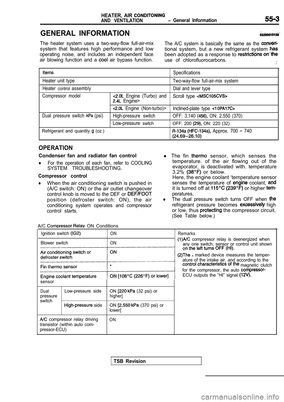
A/C ON Conditions
Ignition switch
Blower switch
ON
ON Remarks
compressor relay is deenergized when
anv one switch, sensor or control unit shown
l marked device measures the temper-
ature of the intake air, and according to the
magnetic clutch
for the compressor, the auto
ECU outputs the “HI” signal
sensor
DualLow-pressure side ON (32 psi) or
pressure
higher]
switch side ON (370 psi) or
lower]
compressor relay driving
transistor (within auto com-
pressor-ECU)ON
TSB Revision
Page 2048 of 2103
55-8HEATER, AIR
AND VENTILATION Troubleshooting/On-vehicle Service
Engine (Non-turbo)>
12
Sensor ground
Automatic compressor-ECM power
supply (output side)
Fin sensor power supply
o v
The ignition switch, blower switch andBattery positive
switch areall ONvoltage
The ignition switch, blower switch and
A/C switch are all ON
TROUBLESHOOTING HINTS
l R e f e r t o C O O L I N G S Y S T E M
SHOOTING.
Refer to
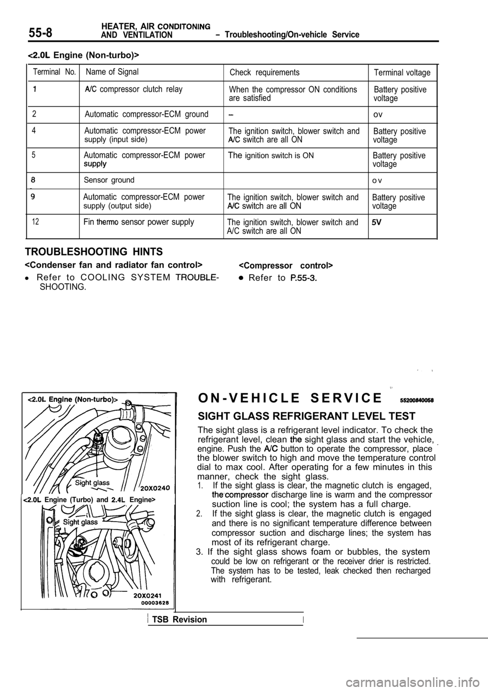
Terminal No.Name of Signal
Check requirements Terminal voltage
compressor clutch relay
When the compressor ON conditions Battery positive
are satisfied voltage
2Automatic compressor-ECM groundov
4Automatic compressor-ECM power
The ignition switch, blower switch and Battery positive
supply (input side) switch are all ONvoltage
5Automatic compressor-ECM powerTheignition switch is ONBattery positive
voltage
Engine (Turbo) and Engine>I
O N - V E H I C L E S E R V I C E
SIGHT GLASS REFRIGERANT LEVEL TEST
The sight glass is a refrigerant level indicator. T o check the
refrigerant level, clean
sight glass and start the vehicle,
engine. Push the button to operate the compressor, place
the blower switch to high and move the temperature control
dial to max cool. After operating for a few minutes in this
manner, check the sight glass.
1.If the sight glass is clear, the magnetic clutch is engaged,
discharge line is warm and the compressor
suction line is cool; the system has a full charge.
2.If the sight glass is clear, the magnetic clutch is engaged
and there is no significant temperature difference between
compressor suction and discharge lines; the system has
most of its refrigerant charge.
3. If the sight glass shows foam or bubbles, the sy stem
could be low on refrigerant or the receiver drier is restricted.
The system has to be tested, leak checked then rech arged
with refrigerant.
TSB RevisionI
Page 2086 of 2103
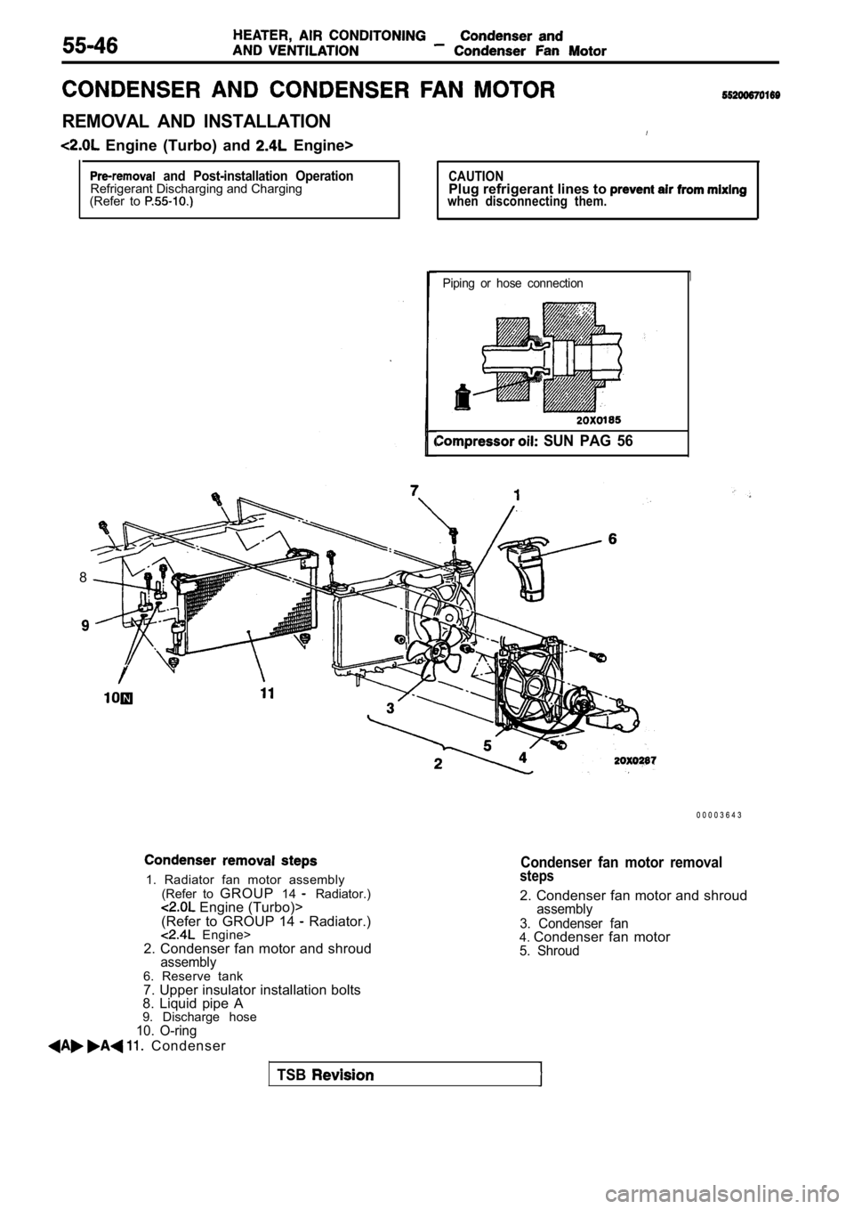
REMOVAL AND INSTALLATION
Engine (Turbo) and Engine>
and Post-installation OperationRefrigerant Discharging and Charging
(Refer to CAUTIONPlug refrigerant lines to when disconnecting them.
Piping or hose connection
SUN PAG 56
1. Radiator fan motor assembly
(Refer to GROUP 14 Radiator.) Engine (Turbo)>
(Refer to GROUP 14 Radiator.) Engine>
2. Condenser fan motor and shroud
assembly6. Reserve tank
7. Upper insulator installation bolts
8. Liquid pipe A
9. Discharge hose
10. O-ring
Condenser
8
0 0 0 0 3 6 4 3
Condenser fan motor removalsteps
2. Condenser fan motor and shroudassembly
3. Condenser fan
4. Condenser fan motor5. Shroud
TSB
Page 2087 of 2103
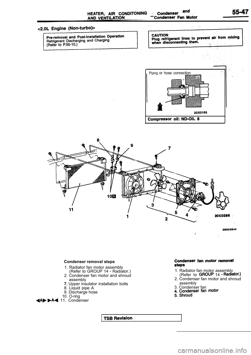
Pipingor hose connection
Condenser removal steps1. Radiator fan motor assembly (Refer to GROUP 14
Radiator.)
2. Condenser fan motor and shroud
assembly Upper insulator installation bolts
8. Liquid pipe A
9. Discharge hose
10. O-ring 11. Condenser
1. Radiator fan motor assembly (Refer to 14 2. Condenser fan motor and shroud
assembly3. Condenser fan
Page 2088 of 2103
HEATER, AIR Condenser and
Condenser Fan’ Motor
TurboNon-turbo
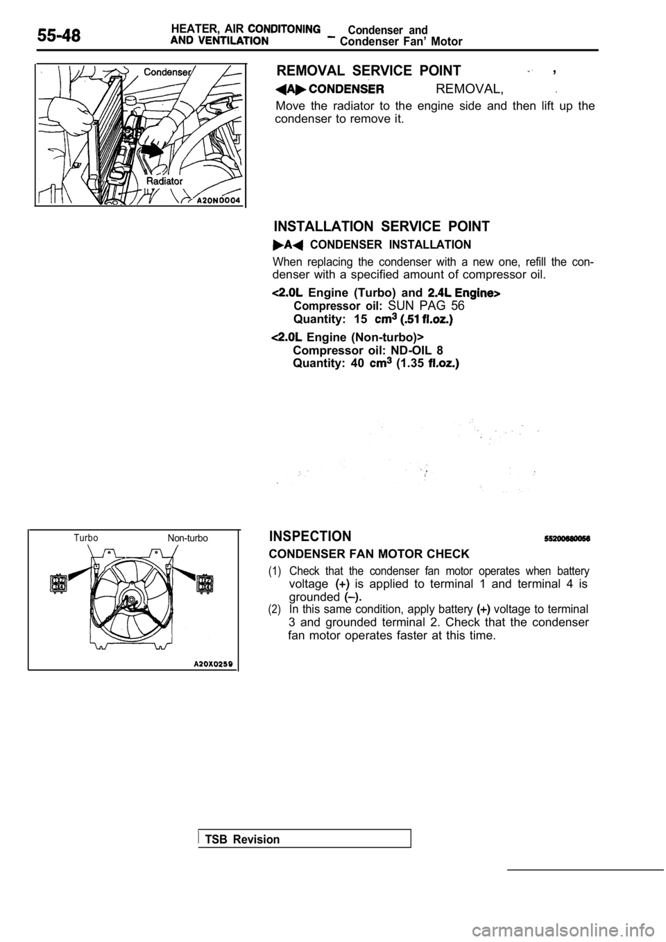
REMOVAL SERVICE POINT ,
REMOVAL,
Move the radiator to the engine side and then lift up the
condenser to remove it.
INSTALLATION SERVICE POINT
CONDENSER INSTALLATION
When replacing the condenser with a new one, refill the con-
denser with a specified amount of compressor oil.
Engine (Turbo) and
Compressor oil: SUN PAG 56
Quantity: 15
Engine (Non-turbo)>
Compressor oil: ND-OIL 8
Quantity: 40
(1.35
INSPECTION
CONDENSER FAN MOTOR CHECK
(1)Check that the condenser fan motor operates when ba ttery
voltage is applied to terminal 1 and terminal 4 is
grounded
(2)In this same condition, apply battery voltage to terminal
3 and grounded terminal 2. Check that the condenser
fan motor operates faster at this time.
TSB Revision
Page 2100 of 2103
8ALPHABETICAL INDEX
PRINTED-HEATER LINE
Check. . . . . . . . . . . . . . . . . . . . . . . . . .
Repair . . . . . . . . . . . . . . . . . . . . . . . . . . .
PROPELLER SHAFT . . . . . . . . . . . . . . . . . . . . . .
PROPORTIONING VALVE
. . . . . . . . . . . . . . . . . . . . . . . . . . . Brakes> . . . . . . . . . . . . . . . , . . . . . . . . . . . .
Function Test . . . . . . . . .
PUMPFuel, Operation Check ENGINE (TURBO) AND ENGINE>. . . . . . . . . . . . . . . . . . . . . . . . . . . . . . . . . .Oil. . . . . . . . . . . . . . . . . . . . . . . . . . . . . . . .. . . . . . . . . . . . . . . . . . . . . . . . . . . . . . . . . . . . .
. . . . . . . . . . . . . . . . . . . . . . . . . . . . .
. . . . . . . . . . . . . . . . . . . . . . . . . . . . . . . . . . . . .
Oil, Pressure Test. . . . . . . . . . . . . . . . . . . . . . . . . . . . . . . .
Water ENGINE (NON-TURBO)>.. . . . . . . . . . . . . . .
ENGINE (TURBO) AND ENGINE>. . .
. . . . . . . . . . . . . . . . . . . . . . . . . . . . . . .11
I
PURGE CONTROL SYSTEM
Check
ENGINE (NON-TURBO)>. . . . . . . . . . . . . . . . ENGINE (TURBO) . . . . . . . . . . . . . . . . . . . . ENGINE>. . . . . . . . . . . . . . . . . . . . . . . . . . . . . .PURGE CONTROL VALVE ENGINE (TURBO)> . . . . .
PURGE PORT VACUUM
Check ENGINE (NON-TURBO)> . . . . . . . . . . .
ENGINE (TURBO) AND .
QUARTER WINDOW GLASS . . . . . . . . , . . . . . . . . .
RADIATOR. . . . . . . . . . . . . . . . . . . . . . . . . . . . . . . . . . . . . . . . . . . .RADIO. . . . . . . . . . . . . . . . . . . . . . . . . . . . . . . . . . . . . . . . . . . . . .REAR AXLE, Total Backlash Check . . . . . . . . . . . . . .REAR AXLE OIL, Maintenance. . . . . . . . . . . . . . . . . . . . . . . . . .REAR BRAKE DISC
Run-out Check. . . . . . . . . . . . . . . . . . . . . . . . . . . . . . . . . . .Run-out Correction. . . . . . . . . . . . . . . . . . . . . . . . . . . . . . .Thickness Check. . . . . . . . . . . . . . . . . . . . . . . . . . . . . . . . .REAR BUMPER. . . . . . . . . . . . . . . . . . . . . . . . . . . . . . . . . . . . . . .REAR CLUTCH
. . . . . . . . . . . . . . . . . . . . . . . . . . . . . . . .. . . . . . . . . . . . . . . . . . . . . . . . . . . . . . . . . . . . . . . .REAR COMBINATION LIGHT. . . . . . . . . . . . . . . . . . . . . . . . . .REAR DISC BRAKE. . . . . . . . . . . . . . . . . . . . . . . . . . . . . . . . .REAR DISC BRAKE PAD, Check and Replacement. . . . . .REAR DRUM BRAKE LININGS. Maintenance. . . . . . . . . . . . .REAR DRUM BRAKE SHOE. . . . . . . . . . . . . . . . . . . . . . . . . .REAR DRUM BRAKE WHEEL CYLINDER. . . . . . . . . . . . .REAR HUB
. . . . . . . . . . . . . . . . . . . . . . . . . . . . . . . . . . . . . . . .. . . . . . . . . . . . . . . . . . . . . . . . . . . . . . . . . . . . . . . . . . . .
Rotary-Sliding Resistance Check . . . . . . . . . . . . . . .REAR SEAT. . . . . . . . . . . . . . . . . . . . . . . . . . . . . . . . . . . . . . . .REAR SUSPENSION. . . . . . . . . . . . . . . . . . . . . . . . . . . . . . . . . . .REAR VIEW MIRROR, Inside. . . . . . . . . . . . . . . . . . . . . . . . .REAR WASHER. . . . . . . . . . . . . . . . . . . . . . . . . . . . . . . . . . . . . .REAR WHEEL ALIGNMENT, Check and Adjustment. . . . . . . .REAR WHEEL CYLINDERS, Maintenance. . . . . . . . . . . . . . . .REAR WINDOW DEFOGGER. . . . . . . . . . . . . . . . . . . . . . . . .REAR WINDOW DEFOGGER SWITCH. . . . . . . . . . . . . . . . .REAR WIPER. . . . . . . . . . . . . . . . . . . . . . . . . . . . . . . . . . . . . . . .RECEIVER DRIER, Test. . . . . . . . . . . . . . . . . . . . . . . . . . . . . . . .
REDUCING PRESSURE, Adjustment ENGINE (TURBO)
AND ENGINE> , . . . . . . . . . . . . . . . . . . . . . . , . . . . , . . .
REFRIGERANT LINE . . . . . . . . . . . . . . . . . . . . . . . . . . . . .
REFRIGERANT, Leak Repair . . . . . . . . . . . . . . . . . . . . . . . . .
REGULATED VOLTAGE
Test ENGINE (NON-TURBO)> . . . . . . . . . . . . . . . . ENGINE (TURBO) AND ENGINE> . . . . . . . . . . . . . . . . . . . . . . . . . . . . . . . . . . .
RELAY
ASD, On-vehicle Inspection
ENGINE (NON-TURBO)> . . . . . . . . . . . . . . .
Fuel Injection On-vehicle Inspection ENGINE (NON-TURBO)> . . . . . . . . . . . . . . . .
ENGINE (TURBO) AND ENGINE>. . . .
Power, Check . . . . . . . . . . . . . . . . . . . . . . . . . . . . . . . . . . .
RESISTANCE, Rotary-sliding, Rear Hub, Check . . .
RESISTOR . . . . . . . . . . . . . . . . . . , . . . . . . . . . . . . . . . . . . . . . . . .
RESISTOR, On-vehicle Inspection ENGINE (TURBO)> . . . . . . . . . . . . . . . . . . . . . . . . .
RHEOSTAT. . . . . . . . . . . . . . . . . . . . . . . . . . . . . . . . . .
ROCKER ARMS
. . . . . . . . . . . . . . . . . . . . . . . . . . . . . . . . . . . . . . . . . . . . . . . . . . . . . . . . . . . . . . . . . . . . . . . . . . . .
ROLL STOPPER, Engine.. . . . . . . . . . . . . . . . . . . . . . . . . . . . . . . ROTARY-SLIDING RESISTANCE, Rear Hub, Check. . . . . . . . . . . . . . . . . . . . . . . . . . . . . . . . . . . . . . . . . . . .ROTOR, Disc Brake, Front, Check. . . . . . . . . . . . . . . . . . . . .
ROWER STEERING PRESSURE SWITCH, Check. . . . . .
RUN-OUT
Front Brake Disc, Check. . . . . . . . . . . . . . . . . . . . . . . . . . .Front Brake Disc, Correction. . . . . . . . . . . . . . . . . . . . . . .
Rear Brake Disc, Check. . . . . . . . . . . . . . . . . . . . . . . . . . .
Rear Brake Disc, Correction. . . . . . . . . . . . . . . . . . . . . . .. . . . . . . . . . . . . . . . . . . . . . . . . . . . . . . . . . . . . . .
SCHEMATIC. . . . . . . . . . . . . . . . . . . . . . . . . . . . . . . . . . . . . . . .SEAL(S)
Ball Joint, Maintenance
. . . . . . . . . . . . . . . . . . . . . . . . . . . . . .Oil. . . . . . . . . . . . . . . . . . . . . . . . . . . . . . .Steering. . . . . . . . . . . . . . . . . . . . . . .
SEAT BELT, Front. . . . . . . . . . . . . . . . . . . . . . . . . . . . . . . . . . .SEAT BELT, Rear. . . . . . . . . . . . . . . . . . . . . . . . . . . . . . . . . . .SEAT
Front. . . . . . . . . . . . . . . . . . . . . . . . . . . . . .. . . . . . . . . .
Rear. . . . . . . . . . . . . . . . . . . . . . . . . . . . . . . . . . . . . . . . . . . .
SELECTOR LEVER
Operation Check ENGINE . . . . . . . . . . . . . . . ENGINE . . . .
SENSOR
Brake Fluid Level, Check . . , . . . . . . . . . . . . . . . . . . , . . . .Camshaft Position ENGINE . .
ENGINE (TURBO)> . . . . . . . .
. . . . . . . . . . . . . . . . .
Crankshaft Position ENGINE (NON-TURBO)> . . .
ENGINE (TURBO)> . . . . . . . .
. . . . . . . . . . . . . . . . .
Engine Coolant Temperature ENGINE (NON-TURBO)> . . . . . . . . . . . . . . . . . . .
ENGINE (TURBO) AND ENGINE>. . . . . . .
Engine Coolant Temperature, On-vehicle Inspection ENGINE (NON-TURBO)> . . . . . . . . . . . . . . . .
ENGINE (TURBO) AND ENGINE>. . . .
Heated 0 On-vehicle Inspection (NON-TURBO)> . . . . . . . . . . . . . ENGINE (TURBO) AND ENGINE> . . . .
Intake Air Temperature ENGINE (NON-TURBO)> . . . . . . . . . . . . . . . . . . .