1990 MITSUBISHI SPYDER radiator
[x] Cancel search: radiatorPage 397 of 2103
ENGINE (NON-TURBO)> Troubleshooting
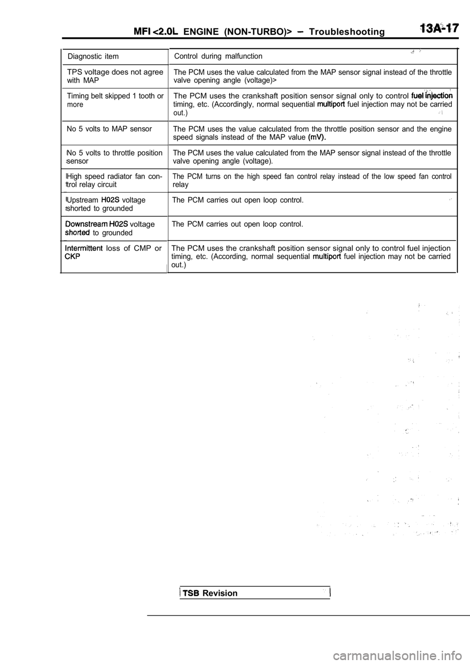
Diagnostic item
TPS voltage does not agree
with MAP
Timing belt skipped 1 tooth or
more
No 5 volts to MAP sensor
No 5 volts to throttle position
sensor
High speed radiator fan con-
trol relay circuit
Upstream
voltage
shorted to grounded
voltage
to grounded
loss of CMP or
Control during malfunction
The PCM uses the value calculated from the MAP sens or signal instead of the throttle
valve opening angle (voltage)>
The PCM uses the crankshaft position sensor signal only to control
timing, etc. (Accordingly, normal sequential fuel injection may not be carried
out.)
The PCM uses the value calculated from the throttle position sensor and the engine
speed signals instead of the MAP value
The PCM uses the value calculated from the MAP sens or signal instead of the throttle
valve opening angle (voltage).
The PCM turns on the high speed fan control relay i nstead of the low speed fan control
relay
The PCM carries out open loop control.
The PCM carries out open loop control.
The PCM uses the crankshaft position sensor signal only to control fuel injection
timing, etc. (According, normal sequential fuel injection may not be carried
out.)
Revision
Page 403 of 2103
E N G I N E
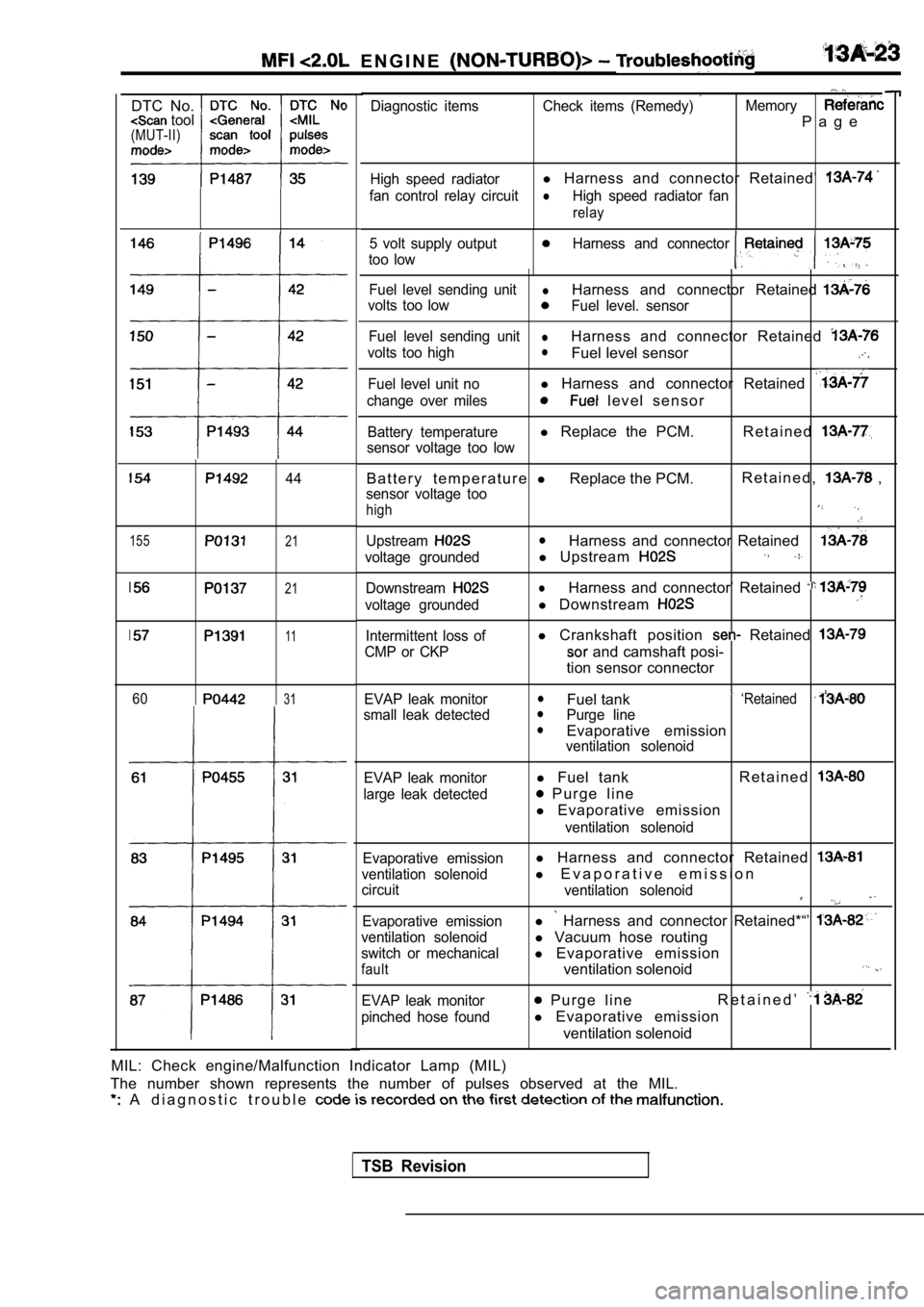
DTC No. tool(MUT-II)
155
44
21
21
11
6031
Diagnostic items Check items (Remedy) Memory
P a g e
High speed radiatorl Harness and connector Retained’
fan control relay circuitlHigh speed radiator fan
relay
5 volt supply outputHarness and connector
too low
Fuel level sending unitlHarness and connector Retained
volts too lowFuel level. sensor
Fuel level sending unit
lHarness and connector Retained
volts too highlFuel level sensor
Fuel level unit nol Harness and connector Retained
change over miles l e v e l s e n s o r
Battery temperaturel Replace the PCM. R e t a i n e d
sensor voltage too low
B a t t e r y t e m p e r a t u r e lReplace the PCM. R e t a i n e d , ,
sensor voltage too
high
UpstreamlHarness and connector Retained
voltage groundedl
Upstream
DownstreamlHarness and connector’ Retained
voltage groundedl Downstream
Intermittent loss of
CMP or CKPl Crankshaft position Retained
and camshaft posi-
tion sensor connector
EVAP leak monitor
small leak detectedlFuel tank ‘RetainedlPurge linelEvaporative emissionventilation solenoid
EVAP leak monitor
large leak detected
l Fuel tank R e t a i n e d
P u r g e l i n e
l Evaporative emission
ventilation solenoid
Evaporative emission
ventilation solenoid
circuit
Evaporative emission
ventilation solenoid
switch or mechanical
fault
l Harness and connector Retained
l E v a p o r a t i v e e m i s s i o n
ventilation solenoid
l Harness and connector Retained*“’
l Vacuum hose routing
l Evaporative emission
ventilation solenoid
EVAP leak monitor
pinched hose found P u r g e l i n e R e t a i n e d ’
l
Evaporative emission
ventilation solenoid
MIL: Check engine/Malfunction Indicator Lamp (MIL)
The number shown represents the number of pulses ob served at the MIL.
A d i a g n o s t i c t r o u b l e
TSB Revision
Page 434 of 2103
![MITSUBISHI SPYDER 1990 Service Repair Manual ENGINE
Scan tool 92
C o d e G e n e r a l s c a n t o o l L o w S p e e d F a n
No.Circuit, 35,
[Comment]l Relay coil open or shortedBackgroundlThe low speed radiator fan re MITSUBISHI SPYDER 1990 Service Repair Manual ENGINE
Scan tool 92
C o d e G e n e r a l s c a n t o o l L o w S p e e d F a n
No.Circuit, 35,
[Comment]l Relay coil open or shortedBackgroundlThe low speed radiator fan re](/manual-img/19/57345/w960_57345-433.png)
ENGINE
Scan tool 92
C o d e G e n e r a l s c a n t o o l L o w S p e e d F a n
No.Circuit, 35,
[Comment]l Relay coil open or shortedBackgroundlThe low speed radiator fan relay controls the low of the radiator fan. l
Ignition switch output circuit openOne side of the relay control coil is supplied with 12 volts when the ignition switch isl
Low speed radiator fan l o r turned to the ON position.
l The circuit is completed when the other side of the relay coil is grounded by the PCM.l .
lThe PCM grounds the relay control circuit depending
on engine coolant temperature etc. . . Range of Checkl
Battery voltage: 10 or morel Ignition switch: ONSet ConditionlAn open or short-circuit condition is detected in t he low speed radiator fan relay controlcircuit for 3 seconds.
NGMeasure at the PCM connector Check the radiator fan relay drcuit.lDisconnect the connector, and measure at the harnes s side.
l Voltage between 55 and ground
(ignition switch: ON)
OK: Battery positive voltage
l Connect a jumper wire between 55 and ground.
(Ignition switch: ON)
OKRadiator fan runs at low speed.
OKNG Repair
OK
Check trouble symptom.
Replace the PCM.
NG
TSB Revision
Page 454 of 2103
![MITSUBISHI SPYDER 1990 Service Repair Manual ENGINE Troubleshooting .
Scan tool 138
Code General scan tool
No. Not
25
[Comment]Range of Check
l Engine:
l Vehicle at rest and the brake appliedSet Conditionl speed differ MITSUBISHI SPYDER 1990 Service Repair Manual ENGINE Troubleshooting .
Scan tool 138
Code General scan tool
No. Not
25
[Comment]Range of Check
l Engine:
l Vehicle at rest and the brake appliedSet Conditionl speed differ](/manual-img/19/57345/w960_57345-453.png)
ENGINE Troubleshooting .
Scan tool 138
Code General scan tool
No. Not
25
[Comment]Range of Check
l Engine:
l Vehicle at rest and the brake appliedSet Conditionl speed differs from target idle by 200 for 12 seconds. l
Idle air control motor failed
l motor related circuit .
SCAN TOOL SENSOR READ TESTS (Data list)
12 position (Refer to Check the air control motor. (Refer to
OK
Check the throttle body minimum air flow. (Refer to
Code
No. R e l a y
General scan tool High Speed Radiator Fan Control
[Comment]
Background
lThe high speed radiator fan relay controls the high speed operation of the radiator fan.lOne side of the relay control coil is supplied with 12 volts when the switch is
turned to the ON position.
lThe circuit is completed when the other side of the relay coil is grounded by the PCM.lThe PCM grounds the relay control circuit depending on engine coolant temperature and/or A/C compressor condition, etc.
Range of Check
l Battery voltage: 10
or more
l Ignition switch: ON
Set Condition
lAn open or shorted condition is detected in the hig h speed radiator fan relay control circuitfor 3 seconds.
Probable cause
TSB Revision
l Relay open or l Ignition switch output lLow speed radiator fan relay control circuit
open or shorted
NGMeasure at the PCM connector Check the radiator fan circuit.lDisconnect the connector, and measure at harness side. Voltage between 69 and ground(Ignition switch: ON),.
OK: Battery positive voltage .,
l
Connect a jumper wire between 69 and ground(Ignition switch: ON)
OK: Radiator fan runs at high speed.
OK
Check the following connector: N G Repair
OK
Check trouble symptom.1
NG
Replace the PCM.
Page 480 of 2103
![MITSUBISHI SPYDER 1990 Service Repair Manual ENGINE (NON-TURBO)>
INSPECTION PROCEDURE 27
Fan motor relay system (Radiator fan, condenser fan)
[Comment]l Malfunction of fan motor relay
The fan motor relay is controlled by t MITSUBISHI SPYDER 1990 Service Repair Manual ENGINE (NON-TURBO)>
INSPECTION PROCEDURE 27
Fan motor relay system (Radiator fan, condenser fan)
[Comment]l Malfunction of fan motor relay
The fan motor relay is controlled by t](/manual-img/19/57345/w960_57345-479.png)
ENGINE (NON-TURBO)>
INSPECTION PROCEDURE 27
Fan motor relay system (Radiator fan, condenser fan)
[Comment]l Malfunction of fan motor relay
The fan motor relay is controlled by the power tran sistor inside the PCM turning ON and OFF l
Malfunction of fan motor
.improper connector contact, open or
short-circuited wire
l Malfunction of the PCM
Measure at PCM connectors
lDisconnect the connector, and measure at the harnes s RepairA-lA-l 07side.lVoltage between 19 and ground, 55 and ground and
69 and ground (Ignition switch: ON)
OK: Battery positive voltage
lConnect a jumper wire between 19 and ground, and
69 and ground (Ignition switch: ON)
OK:Radiator fan and condenser fan run at high speed.lConnect a jumper wire between 55 and ground (Igniti on
switch: ON).
OK
Check symptom.
1Replace the
OK: Radiator fan runs at low speed.
lCheck the radiator fan circuit (Refer to ELEC-TRICAL WIRING.) (Refer to ELECTRICAL WIRING.)
l Check the A/C condenser fan circuit.
(Refer to ELECTRICAL WIRING.) (Refer to ELECTRICAL WIRING
INSPECTION PROCEDURE 28
Ignition circuit system1
[Comment]
The PCM interrupts the ignition coil primary curren t by turning the ignition power transistor inside
the PCM ON and OFF.
TSB
Malfunction of relay Improper connector contact, circuit Or
short-circuited
l Malfunction of the PCM
NG
Measure at the ignition coil connector Check the following RepairlDisconnect the connector and measure at the harnessside. OK SCAN TOOL Actuator test
relay relay) is turned on and off every 1
[Measure with relay on.]
Check trouble
C h e c k t h e h a r n e s s b e t w e e n relay OK relay) and ignition coil switch Repair, if
Check the harness wire between PCM and ignition coi l
connector. if
Page 496 of 2103
ENGINE (NON-TURBO)> , ,
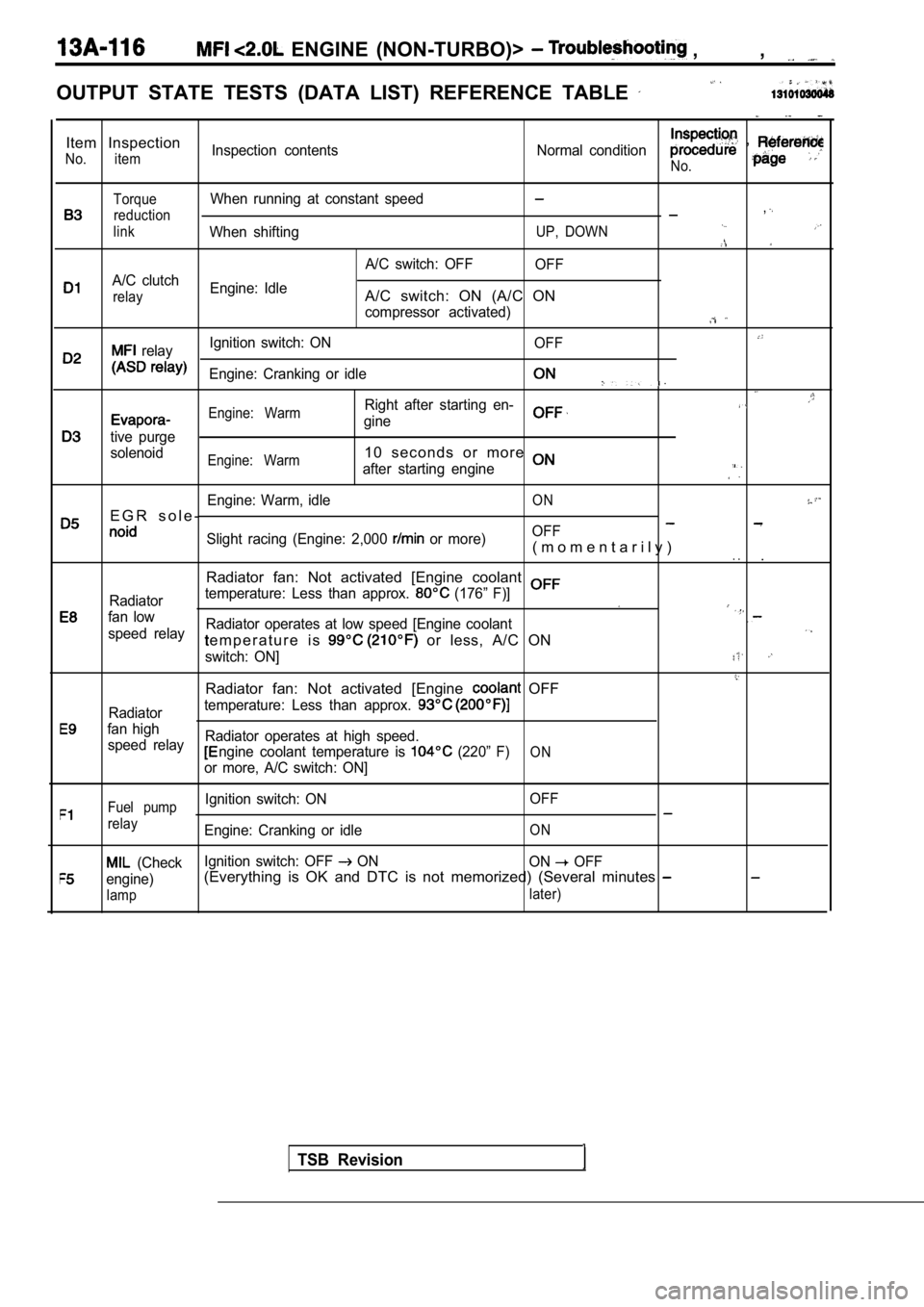
OUTPUT STATE TESTS (DATA LIST) REFERENCE TABLE
Item Inspection
No. itemInspection contentsNormal condition ,
No.
TorqueWhen running at constant speed
reduction,
linkWhen shiftingUP, DOWN
A/C switch: OFFOFF
A/C clutch
relayEngine: IdleA/C switch: ON (A/C ON
compressor activated)
relayIgnition switch: ON
OFF
Engine: Cranking or idle
Engine: WarmRight after starting en-
gine
tive purge
solenoid
Engine: Warm1 0 s e c o n d s o r m o r e
after starting engine
Engine: Warm, idleON
E G R s o l e -OFFSlight racing (Engine: 2,000 or more)( m o m e n t a r i l y ). ..
Radiator fan: Not activated [Engine coolant
Radiator temperature: Less than approx. (176” F)]
fan lowRadiator operates at low speed [Engine coolantspeed relaye m p e r a t u r e i s or less, A/C ON
switch: ON]
Radiator fan: Not activated [Engine OFF
Radiatortemperature: Less than approx.
fan high
speed relay Radiator operates at high speed.
ngine coolant temperature is (220” F)ON
or more, A/C switch: ON]
Fuel pumpIgnition switch: ON
OFF
relayEngine: Cranking or idleON
(CheckIgnition switch: OFF ON
ON OFF
engine)(Everything is OK and DTC is not memorized) (Severa l minutes
lamp later)
TSB Revision
Page 497 of 2103
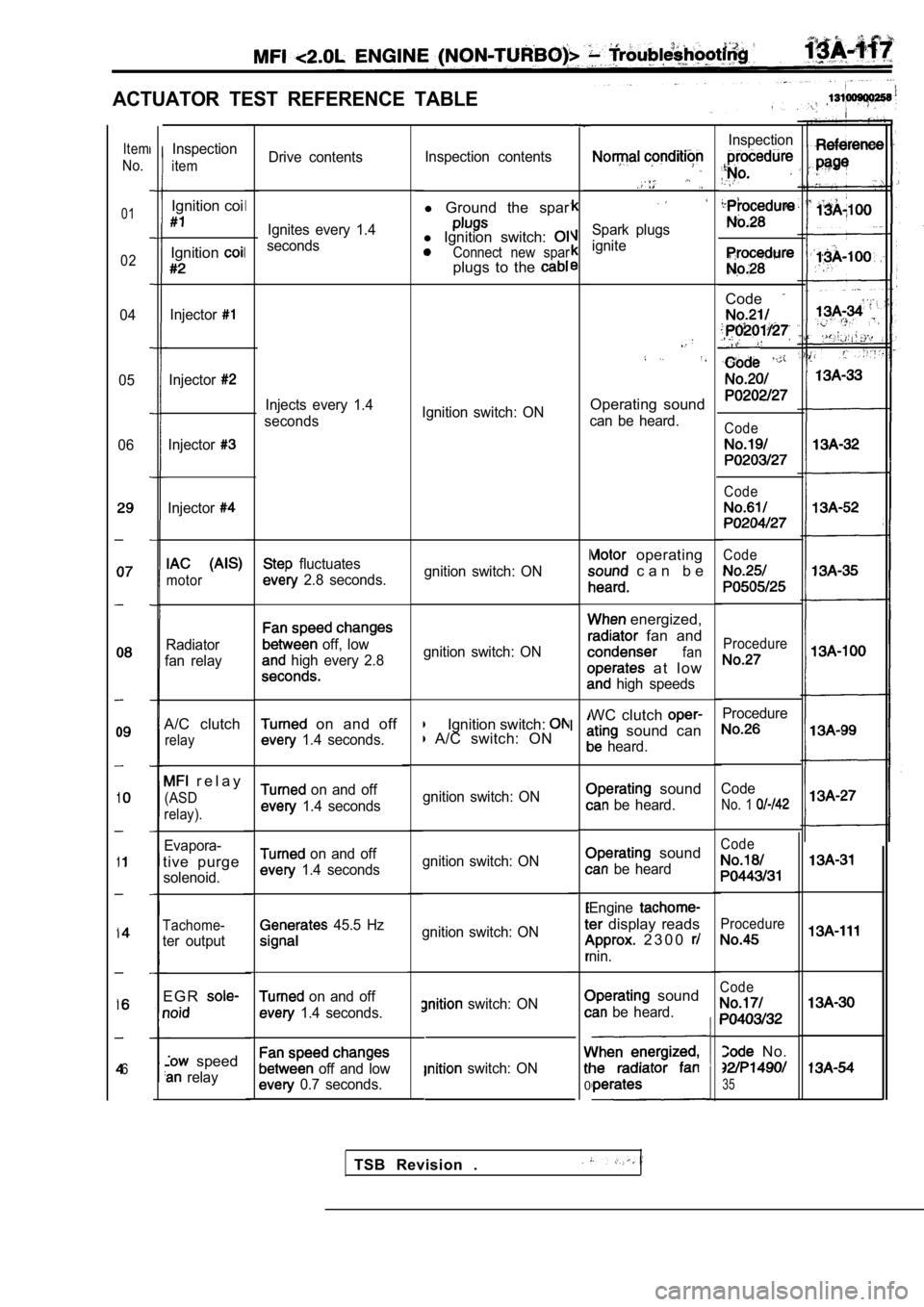
ACTUATOR TEST REFERENCE TABLE
Drive contentsInspection contents
l
Ground the spar
l Ignition switch: Connect new sparplugs to the
Spark plugs
ignite
Ignition switch: ONOperating sound
can be heard.
gnition switch: ON
operating
c a n b e
gnition switch: ON
energized,
fan and
fan
a t l o w
high speeds
Ignition switch: A/C switch: ON WC clutch sound can
heard.
gnition switch: ON
sound
be heard.
gnition switch: ON
sound
be heard
gnition switch: ON Engine
display reads
2 3 0 0
nin.
switch: ON
switch: ON
I
I
0
sound
be heard.
Item
No.
01
02
04
05
06
6
Inspection
Code
,
Code
Code
Code
Procedure
Procedure
Code
No. 1
Code
Procedure
Code
No.
35
Inspection
item
Ignition coi
Ignition
Injector
Injector
Injector
Injector
motor
Radiator
fan relay
A/C clutch
relay
r e l a y
(ASD
relay).
Evapora-
tive purge
solenoid.
Tachome-
ter output
E G R
speed
relay Ignites every 1.4
seconds
I
I
Injects every 1.4
seconds
fluctuates
2.8 seconds.
off, low
high every 2.8
on and off
1.4 seconds.
on and off
1.4 seconds
on and off
1.4 seconds
45.5 Hz
on and off
1.4 seconds.
off and low
0.7 seconds.
TSB Revision .
Page 519 of 2103
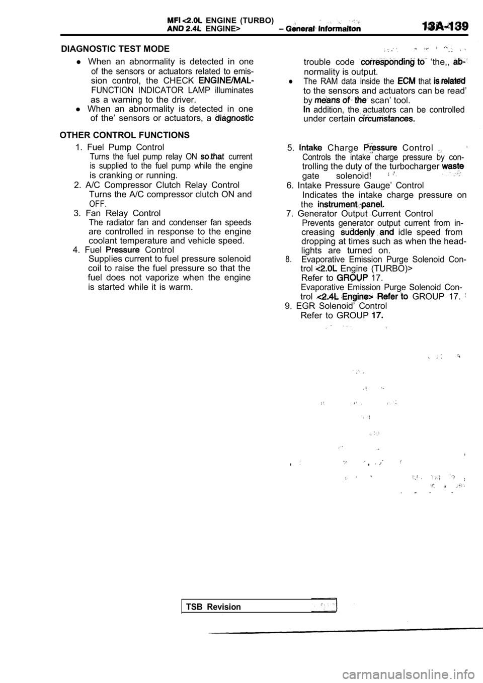
ENGINE (TURBO)
ENGINE>
DIAGNOSTIC TEST MODEl When an abnormality is detected in one
of the sensors or actuators related to emis-
sion control, the CHECK
FUNCTION INDICATOR LAMP illuminates
as a warning to the driver.
l When an abnormality is detected in one
of the’ sensors or actuators, a
OTHER CONTROL FUNCTIONS
1. Fuel Pump Control
Turns the fuel pump relay ON current
is supplied to the fuel pump while the engine
is cranking or running.
2. A/C Compressor Clutch Relay Control Turns the A/C compressor clutch ON and
OFF.
3. Fan Relay Control
The radiator fan and condenser fan speeds
are controlled in response to the engine
coolant temperature and vehicle speed.
4. Fuel
Control
Supplies current to fuel pressure solenoid
coil to raise the fuel pressure so that the
fuel does not vaporize when the engine
is started while it is warm.
trouble code ‘the,,
normality is output.
lThe RAM data inside the that
to the sensors and actuators can be read’
by
scan’ tool.
addition, the actuators can be controlled
under certain
5. Charge Control
Controls the intake charge pressure by con-
trolling the duty of the turbocharger
gate solenoid!
6. Intake Pressure Gauge’ Control Indicates the intake charge pressure on
the
7. Generator Output Current Control
Prevents generator output current from in-
creasing idle speed from
dropping at times such as when the head-
lights are turned on.
8.Evaporative Emission Purge Solenoid Con-
trol Engine (TURBO)>
Refer to
17.
Evaporative Emission Purge Solenoid Con-
trol GROUP 17.
9. EGR Solenoid’ Control
Refer to GROUP
,,
,
TSB Revision