1990 MITSUBISHI SPYDER cooling
[x] Cancel search: coolingPage 278 of 2103
ENGINE O n - v e h i c l e
Press the scan tool clear key (select aforced driving
cancel mode) to release the ACTUATOR TEST
NOTE
If the test is not a forced driving will continue
for 27 minutes. Driving under this condition may damage
the engine.
Check that the actual ignition timing is at the st andard
value.
Standard value: Approx. BTDC
NOTE
Ignition timing is variable within about even under
normal operating.
2. And it is automatically further advanced by abou t
from BTDC at higher altitudes.
CURB IDLE SPEED CHECK
Before inspection and adjustment, set vehicles in the
following condition.
lEngine coolant temperature:
lLights, electric cooling fan and all accessories: OFF
lTransaxle: Neutral (P range on vehicles with A/T)
2. Turn the ignition switch to OFF and connect the scan
tool to the data link connector.
3. Select No. 17 of the SCAN TOOL ACTUATOR TEST
4. Check the basic ignition timing.
Standard value: BTDC
5. Run the engine at idle for 2 minutes.
6. Select No. 22 of the SCAN TOOL DATA LIST.
7. Check the curb idle speed.
Standard value: 750 100
NOTE
The idle speed is controlled automatically by the i dle air
control system.
8. If the idle speed is outside the standard value, check
the components by referring to GROUP Trou-
bleshooting.
IDLE MIXTURE CHECK
Before inspection, set vehicles in the following co ndition:
lEngine coolant temperature:
lLights, electric cooling fan and all accessories: O FF
lTransaxle: Neutral (P range on vehicles with
2. Turn the ignition switch to OFF and connect the scan
tool to the data link connector.
3. Select No. 17 of the SCAN TOOL ACTUATOR TEST.
4.Check that the basic ignition timing is within the standard
value..
Standard value:
TSB Revision
Page 279 of 2103

On-vehicle
Run the engine.
8. Set CO, HC tester.
7. Check the CO contents and the HC contents at idle.
Standard value:
CO contents: 0.5% or less
HC contents: 100 ppm or less
8. the standard value is exceeded, check the following
items:
l Diagnostic output
l Closed-loop control (When the closed-loop control
is carried out normally, the output signal of the heated
oxygen sensor and
at idle.)
l
Injector
lIgnition coil, spark plug
l system the
l Evaporative emission
Compression ,
NOTE,
Replace the three-way CO and
HC contents do not
the value.
(even though the
of the” on
all items.)
PRESSURE CHECK
1.Before inspection, check that the engine oil, start er and
battery are normal. Also, set the vehicle to the fo llowing
condition:
lEngine coolant temperature:
lLights, electric cooling fan and all accessories: O FF
lTransaxle: Neutral (P range on vehicles with
2. Disconnect the spark plug cables.
3. Remove all of the spark plugs.
4. Disconnect the crankshaft position sensor
NOTE
Doing this will prevent the engine control unit fro m carrying
out ignition and fuel injection.
TSB Revision
Page 280 of 2103
ENGINEOn-vehicle
5. Cover the spark plug hole with a shop towel etc., and
after the engine has been cranked, check that no foreign
material is adhering to the shop towel.
Caution
1.Keep away from the spark plug hole when crank-
ing.
2. If compression is measured with water, fuel,
etc., that has come from cracks inside the
these materials will become heated and gush
out from the spark plug hole, which is dangerous.
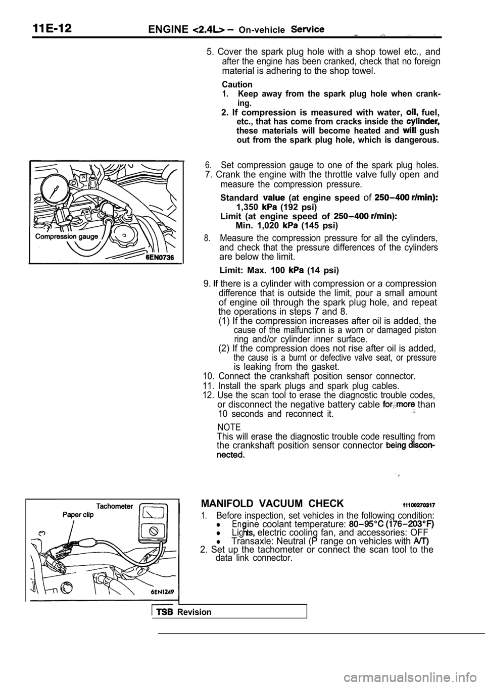
6.Set compression gauge to one of the spark plug hole s.
7. Crank the engine with the throttle valve fully open and
measure the compression pressure.
Standard (at engine speed of
1,350 (192 psi)
Limit (at engine speed of
Min. 1,020 (145 psi)
8.Measure the compression pressure for all the cylind ers,
and check that the pressure differences of the cyli nders
are below the limit.
Limit: Max. 100 (14 psi)
9. there is a cylinder with compression or a compression
difference that is outside the limit, pour a small amount
of engine oil through the spark plug hole, and repe at
the operations in steps 7 and 8.
(1) If the compression increases after oil is added , the
cause of the malfunction is a worn or damaged pisto n
ring and/or cylinder inner surface.
(2) If the compression does not rise after oil is added,
the cause is a burnt or defective valve seat, or pr essure
is leaking from the gasket.
10. Connect the crankshaft position sensor connecto r.
11. Install the spark plugs and spark plug cables.
12. Use the scan tool to erase the diagnostic troub le codes,
or disconnect the negative battery cable than
10 seconds and reconnect it.
NOTE
This will erase the diagnostic trouble code resulting from
the crankshaft position sensor connector
MANIFOLD VACUUM CHECK
1.Before inspection, set vehicles in the following co ndition:
lEn
lLig electric cooling fan, and accessories: OFF
ine coolant temperature:
lTransaxle: Neutral (P range on vehicles with
2. Set up the tachometer or connect the scan tool t o the
data link connector.
Revision
Page 535 of 2103
ENGINE (TURBO)
AND
ENGINE> Troubleshooting .
6. Other monitoring
lMisfire
l Evaporative emission control system
l Idle air control system
l Manifold differential pressure sensor
lExcessive time to enter closed loop fuel control
l Throttle position sensor
l Barometric pressure sensor
Intake air temperature sensor
l Serial communication link
l Crankshaft position sensor
l Camshaft position sensor
Volume air flow sensor
Test conditions/procedure
l Engine coolant temperature sensor
l Closed throttle position switch
l Generator terminal circuit
l sensor circuit
l sensor heater circuit
Turbocharger waste gate solenoid
l EGR solenoid
lEvaporative emission purge solenoid
l Evaporativeemissionventilation
solenoid Engine>
l Fuel pressure solenoid
lInjector circuit
1. All of the following conditions should be satisf ied when the drive test is carried out.
(1) Engine coolant temperature:
or higher (when engine is fully warmed up)
(2) Outside air temperature:
or higher
(3)
condition:
lSelector lever position: range
l Overdrive switch: ON
lPower/economy changeover switch: Power
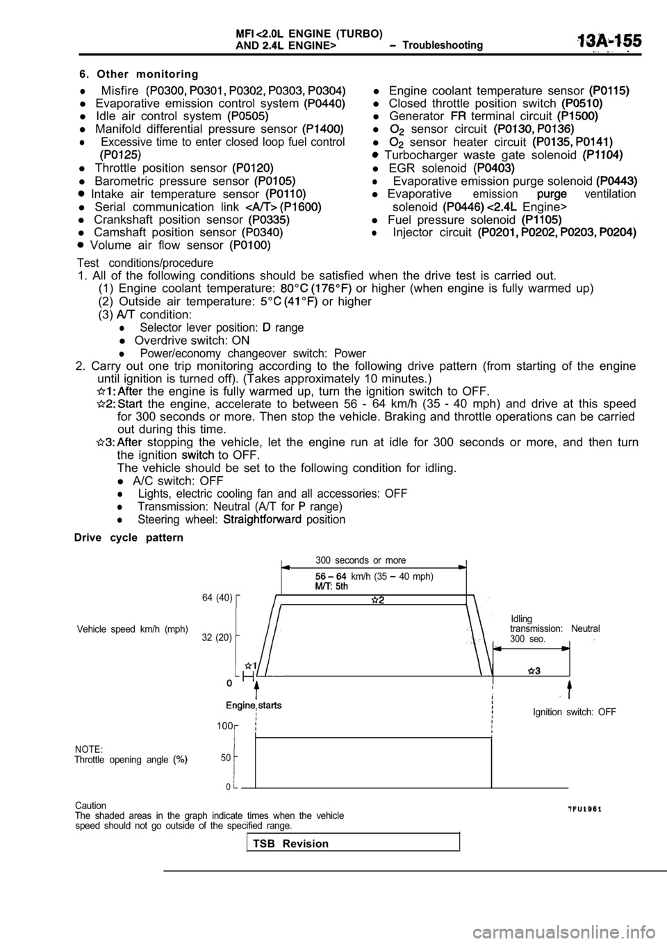
2. Carry out one trip monitoring according to the f ollowing drive pattern (from starting of the engine
until ignition is turned off). (Takes approximately 10 minutes.)
the engine is fully warmed up, turn the ignition s witch to OFF.
the engine, accelerate to between 56 64 km/h (35 40 mph) and drive at this speed
for 300 seconds or more. Then stop the vehicle. Bra king and throttle operations can be carried
out during this time.
stopping the vehicle, let the engine run at idle f or 300 seconds or more, and then turn
the ignition
to OFF.
The vehicle should be set to the following conditio n for idling.
l A/C switch: OFF
lLights, electric cooling fan and all accessories: O FF
lTransmission: Neutral (A/T for range)
lSteering wheel: position
Drive cycle pattern
300 seconds or more
km/h (35 40 mph)
64 (40)
Idling
Vehicle speed km/h (mph) transmission: Neutral
32 (20)
300 seo.
,
Ignition switch: OFF
100
NOTE:Throttle opening angle 50
0
Caution
The shaded areas in the graph indicate times when t he vehicle
speed should not go outside of the specified range.
TSB Revision
Page 619 of 2103
ENGINE (TURBO)
AND ENGINE>
Caution
1. Always apply the brakes when shifting the select or lever to ran&, or vehicle will
forward.
2. Driving tests always need another personnel.
NOTE
In a new vehicle [driven approximately 500 km (300 mile) or less], the volume air sensor output
is sometimes 10 higher than the standard frequency.
The injector drive time represents the time when the cranking speed is at 250 or below when the
supply voltage is 11 V.
In a new vehicle [driven approximately 500 km (300 mile) or less], the injector drive time is sometimes
longer than the standard time.
Fuel is injected into all cylinders simultaneously.
In a new vehicle [driven approximately km (300 mile) or less], the step of the stepper mo tor is sometimes
30 steps greater than the standard value.
If the throttle position sensor voltage rises 100 from the voltage when the engine is at idle and th e
closed throttle position switch turns from on to of f at this time, the sensors are normal. If the throttle position
sensor voltage rises 100
from the voltage when the engine is at idle, the t hrottle valve opens, and the
closed throttle position switch turns from on to of f at this, time, the sensors should be adjusted.
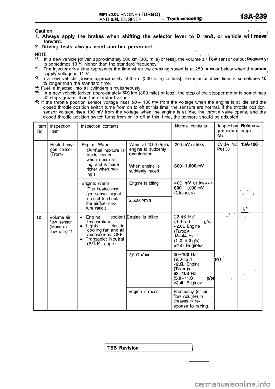
Item Inspection
No.item
Inspection contents Normal contentsInspection
procedure page
11HeatedEngine: WarmWhen at 4000 200 or Code No.
gen sensor engine is suddenly(Air/fuel mixture is 30
(Front)
made leaner
when decelerat- ing, and is made
richer when
When engine is
suddenly raceding.)
Engine: Warm Engine is idling
400 or
(The heated 1,000 ,gen sensor signal(Changes)
is used to check
2,500
the air/fuel mix-
ture ratio.)
Volume airl Engine coolant Engine is idling 22-46 Hz’
flow sensortemperature(4.3-5.3 g/s)
(Mass airl
Lights,electric
flow rate) cooling fan and all Engine
accessories: OFF(Turbo)>
l Transaxle: Neutral Hz
range)(1 g/s)
2,500
Engine is raced
Hz
(9.8-12.1
Engine,
Hz ,
Engine>
Frequency (or air
flow volume) in
creases
re- ,
sponse to racing.
TSB Revision
Page 622 of 2103
E N G I N E
AND ENGINE>. . .
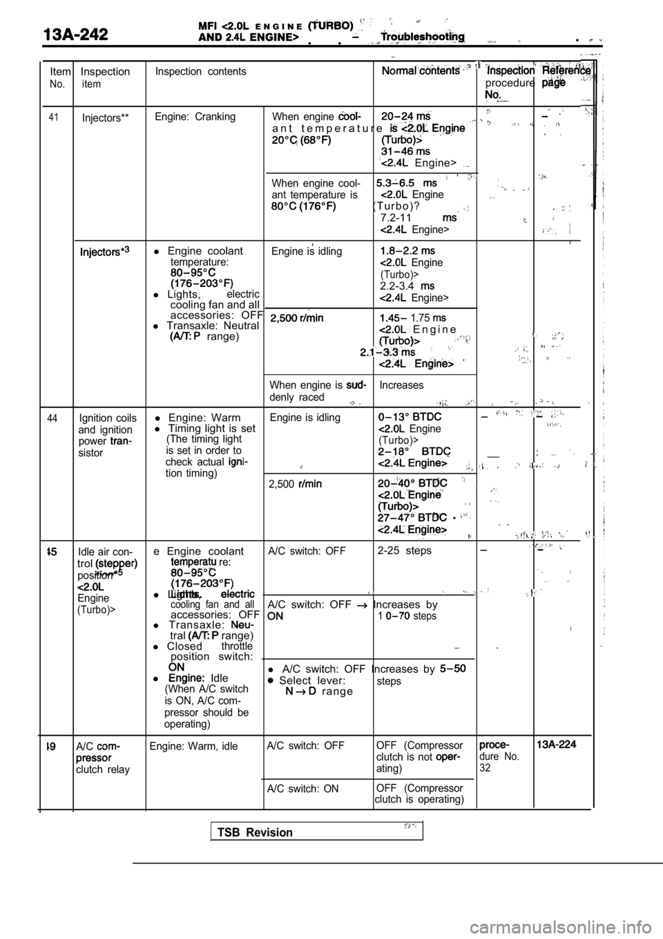
Item Inspection
No. item
41Injectors**Inspection contents
Engine: Cranking
procedure
When engine
a n t t e m p e r a t u r e
Engine>
When engine cool-
ant temperature is Engine
( T u r b o ) ?
7.2-11
.
Engine>
,l Engine coolantEngine is idlingtemperature: Engine
(Turbo)>
2.2-3.4l Lights,electriccooling fan and all Engine>
accessories: OFF l Transaxle: Neutral 1.75
range) E n g i n e
44
When engine is Increases
denly raced
.
Ignition coilsl Engine: WarmEngine is idling
and ignitionl Timing light is set Engine
power(The timing light
sistor is set in order to(Turbo)>
check actual __
tion timing)2,500
. .
.
,
Idle air con-e Engine coolantA/C switch: OFF2-25 steps
trol
position*
re:
l
Lights,Engine
(Turbo)> cooling fan and allA/C switch: OFF Increases by
accessories: OFF
l Transaxle:1 steps
tral range)
l Closedthrottle .
position switch:
l
Idle l
A/C switch: OFF Increases by Select lever:(When A/C switch
is ON, A/C com- r a n g esteps
pressor should be
operating)
A/C
clutch relay Engine: Warm, idle
A/C switch: OFF
A/C switch: ON OFF (Compressor
clutch is not dure No.
ating)32
OFF (Compressor
clutch is operating)
TSB Revision
Page 623 of 2103
E N G I N E ( T U R B O ) .AND ENGINE>
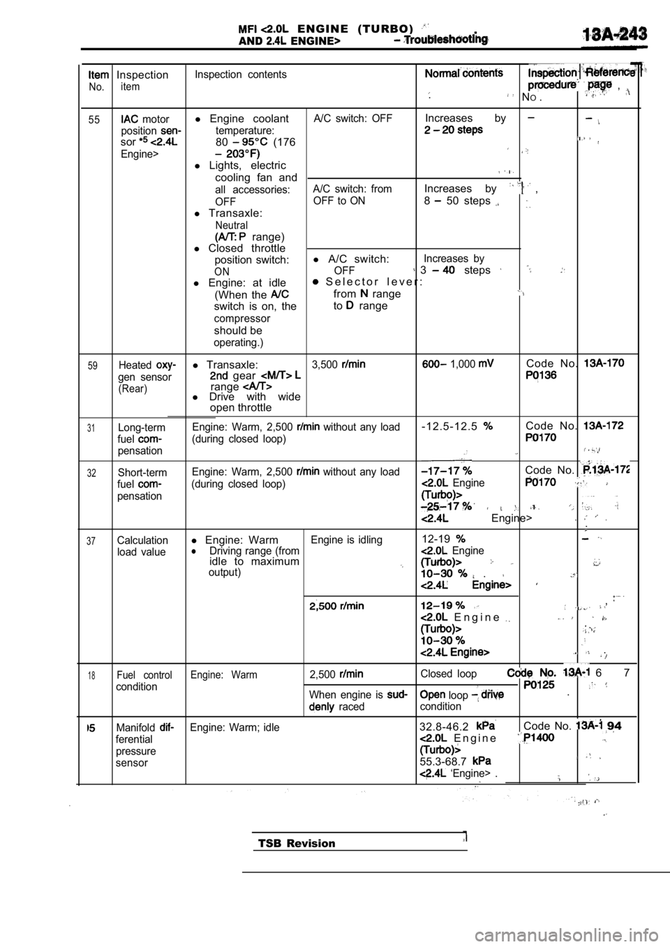
Inspection
No.item
Inspection contents , . N
O.
55 motorl Engine coolantA/C switch: OFFIncreases by
positiontemperature:
sor80 (176
Engine>
l Lights, electric
cooling fan and
all accessories: A/C switch: fromIncreases by ,
OFF OFF to ON8 50 steps
l
Transaxle:
Neutral
range)
l Closed throttle
position switch: l
A/C switch:
Increases by
ONOFF 3 steps
l Engine: at idle S e l e c t o r l e v e r :
(When the
from range
switch is on, the to range
compressor
should be
operating.)
59Heatedl
Transaxle:3,500 1,000 Code No.
gen sensor gear
(Rear)rangel Drive with wide
open throttle
31Long-term
fuel
pensation Engine: Warm, 2,500
without any load- 1 2 . 5 - 1 2 . 5Code No.
(during closed loop)
32Short-term
Engine: Warm, 2,500 without any loadCode No.
fuel(during closed loop) Engine
pensation
Engine> .
37Calculationl
Engine: WarmEngine is idling12-19
load valuelDriving range (from Engineidle to maximumoutput) .
,
E n g i n e
.
1 8Fuel control Engine: Warm2,500Closed loop 6 7
condition loop When engine is .
raced condition
ManifoldEngine: Warm; idle32.8-46.2Code No. 94
ferential E n g i n e
pressure
sensor55.3-68.7
‘Engine> .
TSB Revision
Page 646 of 2103
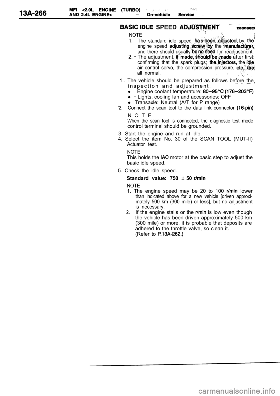
SPEED
NOTE
1.The standard idle speed by,
engine speed the
and there should usually for readjustment.
2. The adjustment, after first:
confirming that the spark plugs; the
air control servo, the compression pressure,
all normal.
1.. The vehicle should be prepared as follows before the
i n s p e c t i o n a n d a d j u s t m e n t .
lEngine coolant temperature:
l Lights, cooling fan and accessories: OFF
‘2.
l Transaxle: Neutral (A/T for range)
Connect the scan tool to the data link connector
N O T E
When the scan tool is connected, the diagnostic tes t mode
control terminal should be grounded.
3. Start the engine and run at idle.
4. Select the item No. 30 of the SCAN TOOL (MUT-II)
Actuator test.
NOTE
This holds the motor at the basic step to adjust the
basic idle speed.
5. Check the idle speed. Standard value: 750
50
NOTE
1. The engine speed may be 20 to 100 lower
than indicated above for a new vehicle [driven appr oxi-
mately 500 km (300 mile) or less], but no adjustment
is necessary.
2.If the engine stalls or the is low even though
the vehicle has been driven approximately 500 km (300 mile) or more, it is probable that deposits ar e
adhered to the throttle valve, so clean it. (Refer to