Page 812 of 2103
(Turbo) and Engine>
PURGE CONTROL CHECK (PURGE FLOW CHECK)
ENGINE>17300140272
IntakeplenumThrottle body
From air cleaner
OFF
ON EVAP purge
solenoid
(ON: OPEN)
hose IPurge flow
indicator
Revision
EVAP canister
Disconnect the purge hose from the evaporative emis sion
(EVAP) canister, and connect the special tool (purg e flow
indicator) between the EVAP canister and the purge hose.
2. The vehicle should be prepared as follows before the
inspection and adjustment.
lEngine coolant temperature:
l Lights, cooling fan and accessories: OFF
l Transaxle: Neutral (A/T for
range)
3. Run the engine at idle for 4 minutes or more.
Page 1044 of 2103
![MITSUBISHI SPYDER 1990 Service Repair Manual AUTOMATIC TRANSAXLE
ENGINE (TURBO) AND ENGINE> ,
INSPECTION PROCEDURE 5 .
lDoes not move (forward or reverse)
[Comment]
P r o b a b l e c a u s e ‘
When the engine is idling, the ve MITSUBISHI SPYDER 1990 Service Repair Manual AUTOMATIC TRANSAXLE
ENGINE (TURBO) AND ENGINE> ,
INSPECTION PROCEDURE 5 .
lDoes not move (forward or reverse)
[Comment]
P r o b a b l e c a u s e ‘
When the engine is idling, the ve](/manual-img/19/57345/w960_57345-1043.png)
AUTOMATIC TRANSAXLE
ENGINE (TURBO) AND ENGINE> ,
INSPECTION PROCEDURE 5 .
lDoes not move (forward or reverse)
[Comment]
P r o b a b l e c a u s e ‘
When the engine is idling, the vehicle does not mov e forward or in reverse even if the selectorl
Abnormal reducing pressure
l
lever is shifted from
to 2, or range. In such cases, the cause is probably abnorm alMalfunction of power train
l
reducing pressure, or a defective oil pump or power train.Malfunction of oil pump
l ‘ o f v a l v e b o d y
Refer to Automatic Transaxle Overhaul
O K
Hydraulic pressure test (Refer to .
l Measure the reducing pressure in range while the
engine is idling.
Standard value:
psi)
NG
Reducing pressure OK
Power train check lDisassemble the transaxle, check the condition of t he
and repair or replace if necessary.
Check to be sure that there are no abnormalities su ch
lIf it is considered that the damage or chipping can
not
be repaired, replace the valve body assembly.If there is an abnormality, replace the oil pump as sembly.
INSPECTION PROCEDURE 6
l Engine stalling during shifting
cause
[Comment] Malfunction of engine systemWhen the engine is idling, the engine stalls when t he selector lever is shifted from to l
2, or range. In such cases, the cause is probably a defe ctive engine system or damper lMalfunction of torque solenoid
clutch control solenoid valve. Malfunction of body l
Malfunction of torque converter
Refer to Automatic Transaxle Overhaul
Enaine check .
l the control system, ignition system, fuel system a nd main engine system, and confirm that everything is l If there is an abnormality, repair or replace the e ngine system.
After completion
Solenoid valve connector check
l Check to be sure that there is no water in the conn ector.
l Check to be sure that none of the terminals are sho
rted to each other.
After completion
Torque converter clutch solenoid check l Check to be sure that the valve is not sticking due to foreign materials packed inside solenoid.
l If there is an abnormality, replace the solenoid as sembly.
After completion
Transaxle cooling system check l Check for plugged cooler lines.
l Check for plugged oil cooler.
After completion
Valve body disassembly, cleaning and reassembly
l
l Pay particular attention to loosening of bolts, and
to damage, chipping or slippage of O-rings, valve intermediate plate and body.
If it is considered that the damage or chipping can not be repaired, replace the valve body assembly.
After completion
Torque converter check l Check to be sure that there is no sticking due to s eparation from the damper clutch.
l If there is an abnormality, replace the torque conv erter assembly.
Revision
Page 1162 of 2103
AUTOMATIC TRANSAXLE
ENGINE Troubleshooting
PROBABLE CAUSE
No.Probable cause
1Low fluid level
2Aerated fluid (High fluid level)
3Worn or damaged reaction shaft support sealing
4worn or damaged input shaft sealing
5Worn pump
6
Damaged or failed underdrive clutch
7Damaged or failed ovedrive clutch
8Damaged or failed reverse clutch
9Damaged or failed 2-4 clutch
10Damaged or failed low/reverse clutch
11Damaged clutch seal
12Worn or damaged accumulator sealing
13Plugged filter
14Stuck/sticky valves
15Solenoid switch valve
16Lock-up switch valve
17Torque converter control valve
18Regulator valve
19Valve body leakage
20Pressures too high
21Internal solenoid leak
22Torque converter clutch failure
23Faulty cooling system
24Damaged speed sensor gear teeth
25Planetary gear sets broken or seized
.
,
TSB Revision
Page 1163 of 2103
AUTOMATIC TRANSAXLE
ENGINE (NON-TURBO)>
INSPECTION MATRIX FOR TROUBLE SYMPTOMS
PROBABLE CAUSE
No.Probable cause
Engine performance
2Worn or faulty underdrive clutch
3Worn of faulty overdrive clutch
4Worn of faulty reverse clutch
5Worn or faulty 2-4 clutch
6Worn or faulty low/reverse clutch
7 dragging
8Insufficient clutch plate clearance
9Damaged clutch seal
10Worn or damaged accumulator sealing(s)
11Faulty cooling system
12Engine coolant temperature too low
13Incorrect gear shift control linkage adjustment
14Shift linkage damaged
15Chipped or damaged gear teeth
16Planetary gear sets broken or seized
17Bearings worn or damaged
,
. .
,
TSB Revision
Page 1258 of 2103
AUTOMATIC TRANSAXLE
OVERHAUL Front Clutch..
21750264
750264
Shear
droopPlate Plate Plate
DISASSEMBLY SERVICE
SNAP RING
(1) Compress the return spring with special tool..
(2) Remove the snap ring.
REASSEMBLY SERVICE POINTS
SNAP RING INSTALLATION
(1) Compress the return spring with the special tool.
(2) Install the snap ring.
CLUTCH REACTION PLATE’:
(1) Install the clutch reaction plate with‘ missing tooth
portions (A in the illustration) in alignment.
NOTE
This design is to facilitate escape of automatic tr ansmis-
sion fluid and improve the cooling efficiency of th e plate
and disc.
. .
(2) Install the innermost the reaction plate with t heir shear
droops directed as shown in the illustration.
Identification of reaction plate
mm (in.)
Plate No.ThicknessIdentification mark
15.0A
23.1
3.1 I
3.7 I
TSB Revision
Page 1261 of 2103

AUTOMATIC
Rear
750274
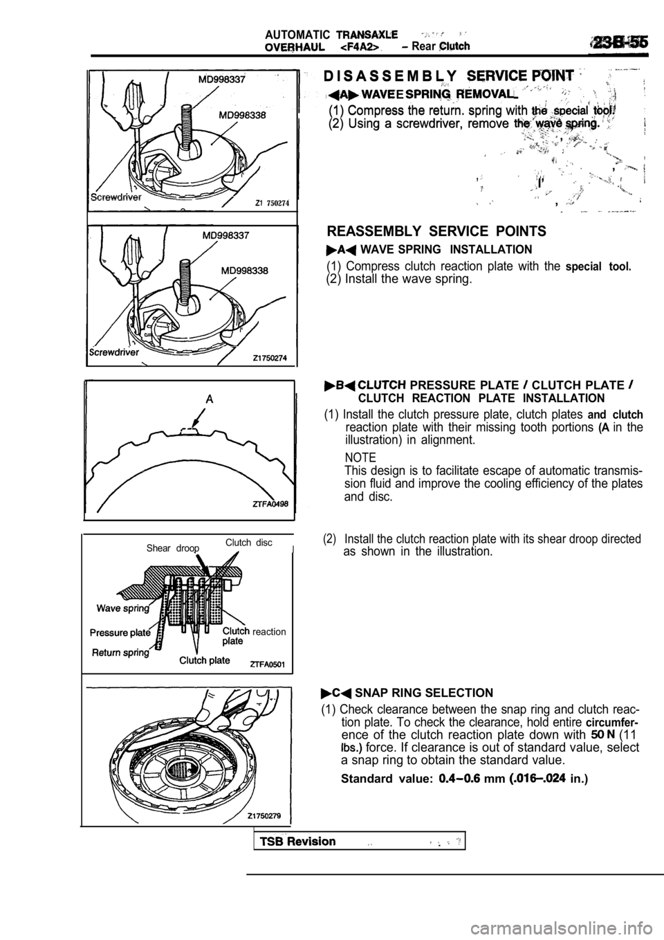
D I S A S S E M B L YD I S A S S E M B L Y
WAVE
(1) Compress the return. spring with (1) Compress the return. spring with
(2) Using a screwdriver, remove (2) Using a screwdriver, remove
,,
,,
,,,,
I’I’
,,
REASSEMBLY SERVICE POINTS
WAVE SPRING INSTALLATION
(1) Compress clutch reaction plate with the special tool.
(2) Install the wave spring.
Shear droopClutch disc,I
reaction
PRESSURE PLATE CLUTCH PLATE
CLUTCH REACTION PLATE INSTALLATION
(1) Install the clutch pressure plate, clutch plate
s and clutch
reaction plate with their missing tooth portions (Ain the
illustration) in alignment.
NOTE
This design is to facilitate escape of automatic tr ansmis-
sion fluid and improve the cooling efficiency of th e plates
and disc.
(2)Install the clutch reaction plate with its shear dr oop directed
as shown in the illustration.
SNAP RING SELECTION
(1) Check clearance between the snap ring and clutc h reac-
tion plate. To check the clearance, hold entire
circumfer-
ence of the clutch reaction plate down with (11
force. If clearance is out of standard value, sele ct
a snap ring to obtain the standard value.
Standard value: mm in.)
Page 1363 of 2103
A U T O M A T I C “ T R A N S A X L E .
SNAP
Compress the return spring with thetool.
(2) Remove the snap ring.
REASSEMBLY SERVICE POINTS
Compress the return spring the special tool.
(2) Install the snap ring.
,
P L A T E
Install the clutch plate with their portions
(A in the illustration) in alignment.
NOTE
This design helps automatic transmission fluid esca pe
and improve the cooling efficiency of the plate and disc.
Plate No. 4 Plate No. 2
ring
Clutch discs
(2)Install the innermost plate droops directed
as shown in the
Plate No.Thickness mm (in.)
15.0
2.2
32.2
Position the gap of the snap ring approx. away
from that of the return spring mounting snap ring.
TSB Revision
2.2
53.8
SNAP RING
Check clearance between the ring and reac-
tion plate. To check the clearance, inside diam-
eter of the clutch reaction plate ‘50 tbs.)
force. If clearance is out of standard a snap
ring to obtain the standard value;,
S t a n d a r d v a l u e :
NOTE
Page 1365 of 2103

A U T O M A T I C
Rear
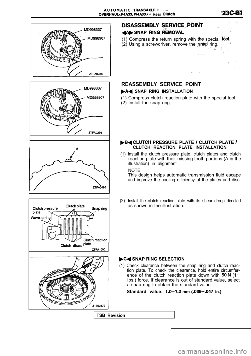
,
(1) Compress the return spring with special
(2) Using a screwdriver, remove the ring.
Clutch discs
REASSEMBLY SERVICE POINT
SNAP RING INSTALLATION
(1) Compress clutch reaction plate with the special tool.
(2) Install the snap ring.
PRESSURE PLATE CLUTCH PLATE
CLUTCH REACTION PLATE INSTALLATION
(1) Install the clutch pressure plate, clutch plate s and clutch
reaction plate with their missing tooth portions (A in the
illustration) in alignment.
NOTE
This design helps automatic transmission fluid esca pe
and improve the cooling efficiency of the plates and disc.
(2)Install the clutch reaction plate with its shear droop directed
as shown in the illustration.
SNAP RING SELECTION
(1) Check clearance between the snap ring and clutc h reac-
tion plate. To check the clearance, hold entire cir cumfer-
ence of the clutch reaction plate down with (11
Ibs.) force. If clearance is out of standard value, select
a snap ring to obtain the standard value.
Standard value:
mm in.)
TSB Revision