1990 MITSUBISHI SPYDER cooling
[x] Cancel search: coolingPage 2004 of 2103
SRS General Information.
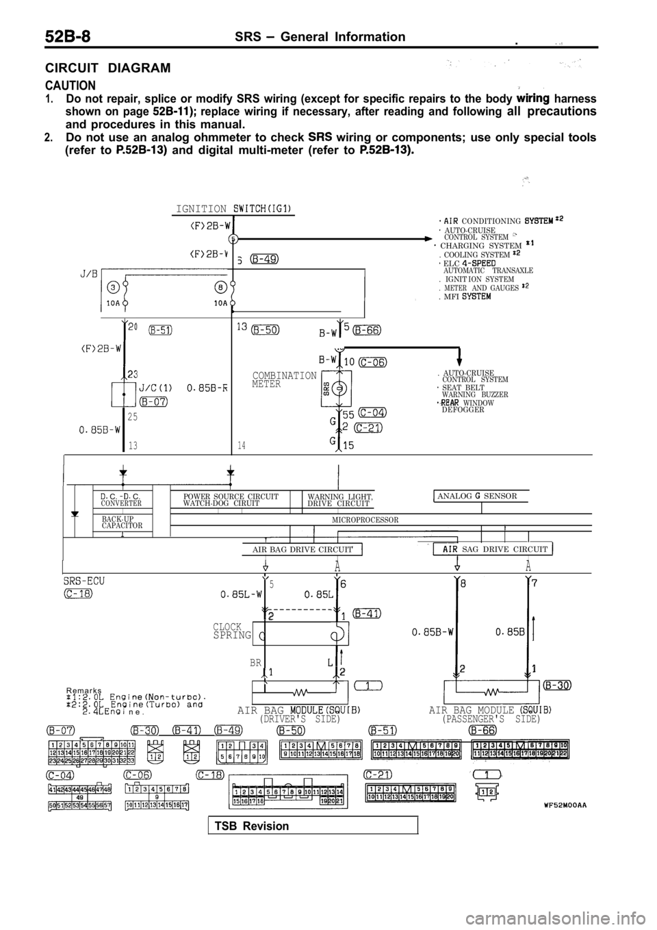
CIRCUIT DIAGRAM
CAUTION
1.Do not repair, splice or modify SRS wiring (except for specific repairs to the body harness
shown on page
replace wiring if necessary, after reading and fol lowing all precautions
and procedures in this manual.
2.Do not use an analog ohmmeter to check wiring or components; use only special tools
(refer to
and digital multi-meter (refer to
IGNITION
23
I
25
13
CONDITIONING AUTO-CRUISECONTROL SYSTEM CHARGING SYSTEM . COOLING SYSTEM
. IGNIT. METER. MFI
ELC AUTOMATIC TRANSAXLE ION SYSTEMAND GAUGES
14
COMBINATIONMETER
. AUTO-CRUISECONTROL SYSTEM SEAT BELTWARNING BUZZER WINDOWDEFOGGER
C. C.POWER SOURCE CIRCUITCONVERTERWATCH-DOG CIRUIT WARNING LIGHT,
DRIVE CIRCUIT ANALOG SENSOR
I IIIBACK-UP
CAPACITORMICROPROCESSORI
AIR BAG DRIVE CIRCUIT
SAG DRIVE CIRCUIT IIIAA
5 6 8
7
2CLOCKSPRINGI
BR2 21
R e m a r k s
n e .AIR BAG AIR BAG MODULE (DRIVER'S SIDE) (PASSENGER'S SIDE)
TSB Revision
Page 2041 of 2103
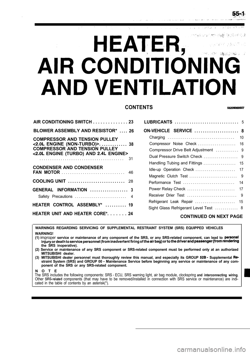
CONTENTS
AIR CONDITIONING SWITCH . . . . . . . . . . . . . . 23
LUBRICANTS. . . . . . . . . . . . . . . . . . . . . . . . . . . . . .5
BLOWER ASSEMBLY AND RESISTOR*
. . . .26
COMPRESSOR AND TENSION PULLEY
ENGINE (NON-TURBO)>.. . . . . . . . . . . .38
COMPRESSOR AND TENSION PULLEY
ENGINE (TURBO) AND ENGINE>
ON-VEHICLE SERVICE. . . . . . . . . . . . . . . . . . . . .8
Charging. . . . . . . . . . . . . . . . . . . . . . . . . . . . . . . . . . .10
Compressor Noise Check. . . . . . . . . . . . . . . . . . . .16
Compressor Drive Belt Adjustment . . . . . . . . . . . .9
. . . . . . . . . . . . . . . . . . . . . . . . . . . . . . . . . . . . . . . .31Dual Pressure Switch Check. . . . . . . . . . . . . . . . . .9
Handling Tubing and Fittings. . . . . . . . . . . . . . . . .15
CONDENSER AND CONDENSER
46Idle-up Operation Check. . . . . . . . . . . . . . . . . . . . .17FAN MOTOR. . . . . . . . . . . . . . . . . . . . . . . . . . . . . .Magnetic Clutch Test. . . . . . . . . . . . . . . . . . . . . . . . .9
COOLING UNIT . . . . . . . . . . . . . . . . . . . . . . . . . . . 28
GENERAL INFORMATION3. . . . . . . . . . . . . . . . . .
Performance Test. . . . . . . . . . . . . . . . . . . . . . . . . . .14
Power Relay Check . . . . . . . . . . . . . . . . . . . . . . . . .17
Safety Precautions. . . . . . . . . . . . . . . . . . . . . . . . . . .4Receiver Drier Test. . . . . . . . . . . . . . . . . . . . . . . . . .9
. . . . . . . . . . . . . . . . . . . . .15HEATER CONTROL ASSEMBLY*19Refrigerant Leak Repair. . . . . . . . . .
Sight Glass Refrigerant Level Test . . . . . . . . . . . .8
HEATER UNIT AND HEATER CORE*. . . . . . . 24CONTINUED ON NEXT PAGE
WARNINGS REGARDING SERVICING OF SUPPLEMENTAL RESTRA
INT SYSTEM (SRS) EQUIPPED VEHICLES
WARNING!
(1)
improperservice or maintenance of any component of the SRS, or any SRS-related component, can lead to
the SRS inoperative).
(2) Service or maintenance of any SRS component or SRS-related component must be performed only at an authorized
MITSUBISHI dealer.
(3)MITSUBISHI dealer personnel must thoroughly review this manual, and especially its GROUP Supplemental straint System (SRS) and GROUP 00 Maintenance Service before beginning any service or maintenance of any com-
ponent of the SRS or any SRS-related component.
N O T EThe SRS includes the following components: SRS ECU, SRS warning light, air bag module, clocksprin g and interconnecting wiring.Other components (that may have to be removed/installed in connection with SRS service or maintenance) are indi-
cated in the table of contents by an asterisk(*).
Page 2043 of 2103
HEATER, AIR
AND VENTILATION General Information
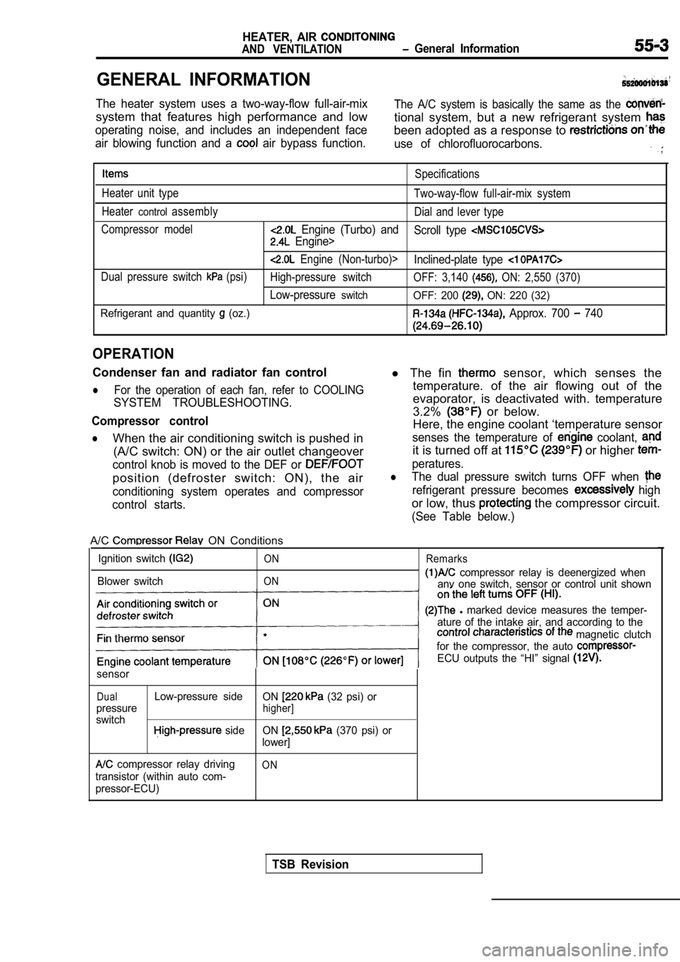
GENERAL INFORMATION
The heater system uses a two-way-flow full-air-mixThe A/C system is basically the same as the
system that features high performance and lowtional system, but a new refrigerant system
operating noise, and includes an independent facebeen adopted as a response to
air blowing function and a air bypass function.use of chlorofluorocarbons. ,
Specifications
Heater unit type Two-way-flow full-air-mix system
Heater
controlassembly Dial and lever type
Compressor model
Engine (Turbo) and Scroll type
Engine>
Engine (Non-turbo)>Inclined-plate type
Dual pressure switch (psi)High-pressure switch OFF: 3,140 ON: 2,550 (370)
Low-pressureswitchOFF: 200 ON: 220 (32)
Refrigerant and quantity
(oz.) Approx. 700 740
OPERATION
Condenser fan and radiator fan control
lFor the operation of each fan, refer to COOLING
SYSTEM TROUBLESHOOTING.
Compressor control
lWhen the air conditioning switch is pushed in (A/C switch: ON) or the air outlet changeover
control knob is moved to the DEF or
position (defroster switch: ON), the air
conditioning system operates and compressor
control starts.
l The fin sensor, which senses the
temperature. of the air flowing out of the
evaporator, is deactivated with. temperature
3.2%
or below.
Here, the engine coolant ‘temperature sensor
senses the temperature of coolant,
it is turned off at or higher
peratures.
lThe dual pressure switch turns OFF when
refrigerant pressure becomes high
or low, thus the compressor circuit.
(See Table below.)
A/C ON Conditions
Ignition switch
Blower switch
ON
ON Remarks
compressor relay is deenergized when
anv one switch, sensor or control unit shown
l marked device measures the temper-
ature of the intake air, and according to the
magnetic clutch
for the compressor, the auto
ECU outputs the “HI” signal
sensor
DualLow-pressure side ON (32 psi) or
pressure
higher]
switch side ON (370 psi) or
lower]
compressor relay driving
transistor (within auto com-
pressor-ECU)ON
TSB Revision
Page 2054 of 2103
HEATER, AIR
AND VENTILATION On-vehicle Service
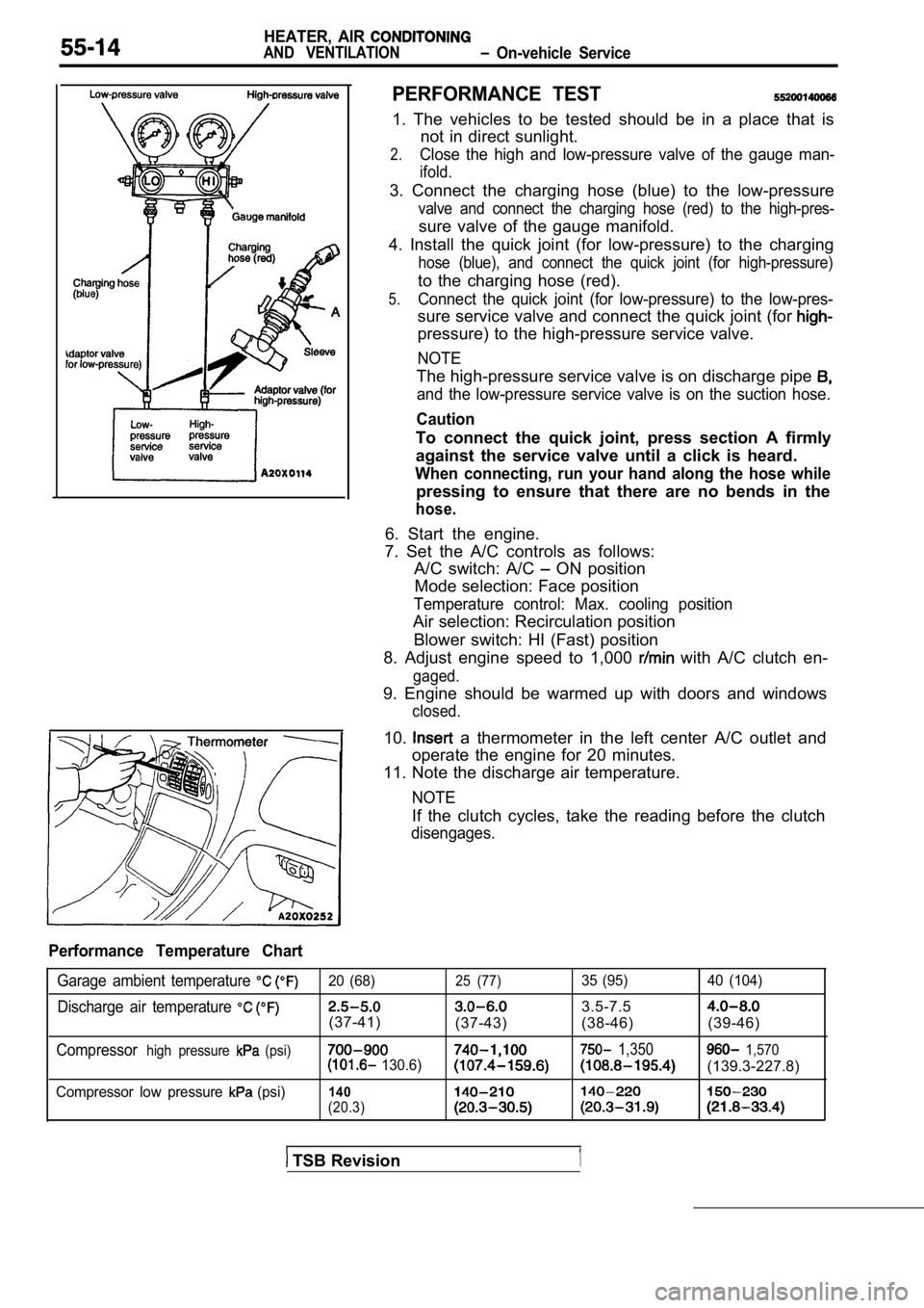
PERFORMANCE TEST
1. The vehicles to be tested should be in a place that is
not in direct sunlight.
2.Close the high and low-pressure valve of the gauge man-
ifold.
3. Connect the charging hose (blue) to the low-pres sure
valve and connect the charging hose (red) to the high-pres-
sure valve of the gauge manifold.
4. Install the quick joint (for low-pressure) to th e charging
hose (blue), and connect the quick joint (for high- pressure)
to the charging hose (red).
5.Connect the quick joint (for low-pressure) to the low-pres-
sure service valve and connect the quick joint (for
pressure) to the high-pressure service valve.
NOTE
The high-pressure service valve is on discharge pip e
and the low-pressure service valve is on the suction hose.
Caution
To connect the quick joint, press section A firmly
against the service valve until a click is heard.
When connecting, run your hand along the hose while
pressing to ensure that there are no bends in the
hose.
6. Start the engine.
7. Set the A/C controls as follows: A/C switch: A/C
ON position
Mode selection: Face position
Temperature control: Max. cooling position
Air selection: Recirculation position
Blower switch: HI (Fast) position
8. Adjust engine speed to 1,000
with A/C clutch en-
gaged.
9. Engine should be warmed up with doors and window s
closed.
10. a thermometer in the left center A/C outlet and
operate the engine for 20 minutes.
11. Note the discharge air temperature.
NOTE
If the clutch cycles, take the reading before the c lutch
disengages.
Performance Temperature Chart
Garage ambient temperature 20 (68)25 (77)35 (95) 40 (104)
Discharge air temperature 3.5-7.5
(37-41)
(37-43) (38-46) (39-46)
Compressorhigh pressure (psi) 1,350 1,570 130.6)(139.3-227.8)
Compressor low pressure (psi)140
(20.3)
TSB Revision1
Page 2057 of 2103
HEATER, AIR
AND VENTILATION On-vehicle Service
IDLE-UP OPERATION CHECK
1,Before inspection and adjustment, set the f&w-
ing condition:
lEngine coolant temperature:
lLights, electric cooling fan and accessories: Set t o
OFF
lTransmission: Neutral (N or for vehicles with
l Steering wheel:
2. Check whether or not the idling speed is the sta ndard
value.
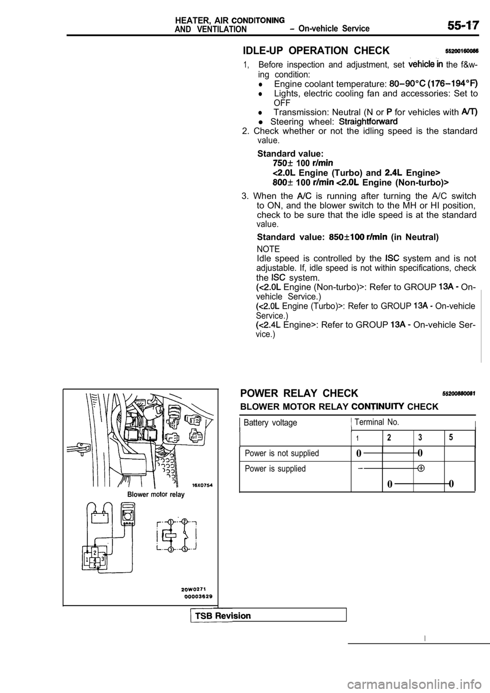
Blower relay
Standard value:
100
Engine (Turbo) and Engine>
100 Engine (Non-turbo)>
3. When the
is running after turning the A/C switch
to ON, and the blower switch to the MH or HI positi on,
check to be sure that the idle speed is at the stan dard
value.
Standard value: (in Neutral)
NOTE
Idle speed is controlled by the system and is not
adjustable. If, idle speed is not within specifications, check
the system.
Engine (Non-turbo)>: Refer to GROUP On-
vehicle Service.)
Engine (Turbo)>: Refer to GROUP On-vehicle
Service.)
Engine>: Refer to GROUP On-vehicle Ser-
vice.)
POWER RELAY CHECK
BLOWER MOTOR RELAY CHECK
Battery voltage Terminal No.III
1235
Power is not supplied
Power is supplied0 0
0 0
Page 2064 of 2103
HEATER, AIR
AND VENTILATION Heater Unit and Heater Core
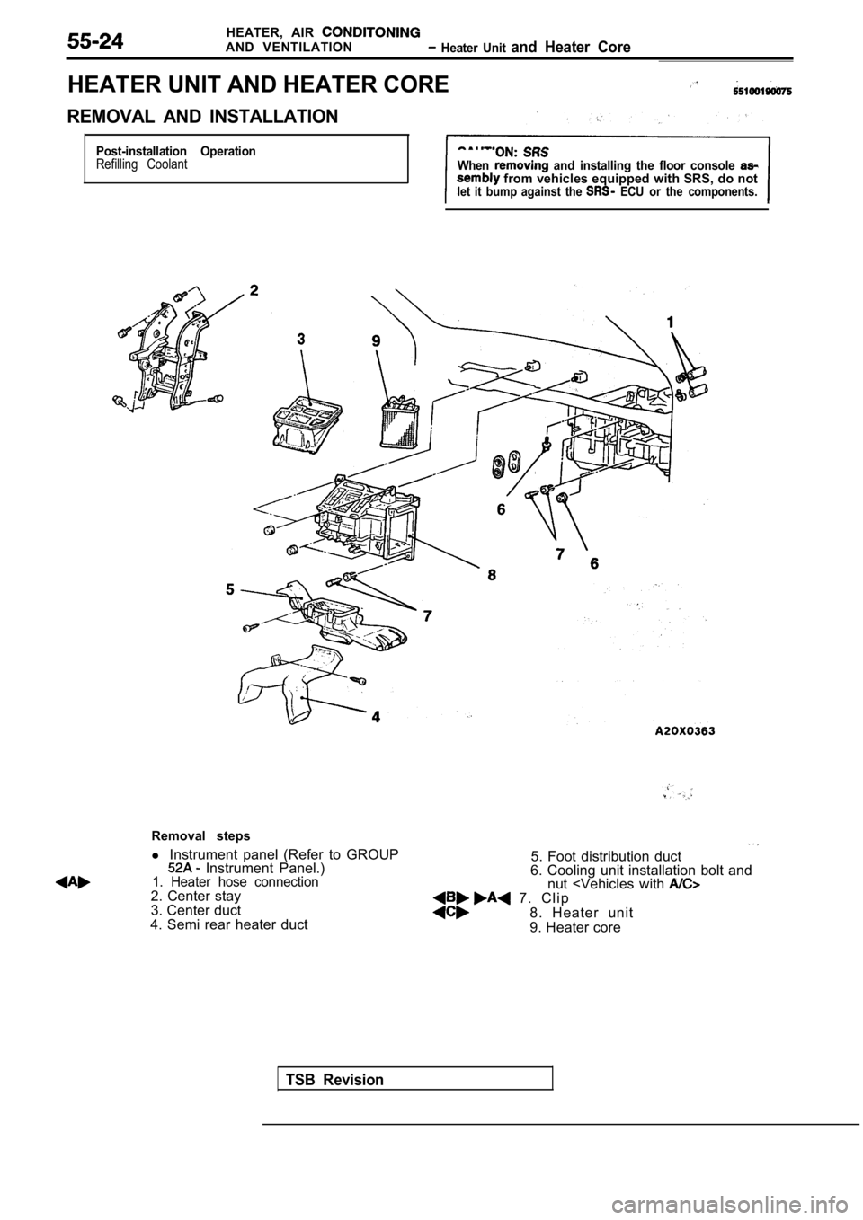
HEATER UNIT AND HEATER CORE
REMOVAL AND INSTALLATION
Post-installation OperationRefilling CoolantWhen and installing the floor console from vehicles equipped with SRS, do notlet it bump against the ECU or the components.
TSB Revision
Removal steps
l Instrument panel (Refer to GROUP
Instrument Panel.)1. Heater hose connection2. Center stay
3. Center duct
4. Semi rear heater duct
5. Foot distribution duct
6. Cooling unit installation bolt and nut
8. Heater unit
9. Heater core
Page 2065 of 2103
HEATER, AIR
AND VENTILATION Heater Unit
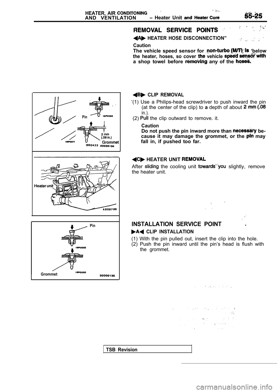
HEATER HOSE DISCONNECTION”
Caution
The vehicle speed sensor for ‘below
the heater, hoses, so cover vehicle
a shop towel before any of the
Pin
Grommet
Pin
CLIP REMOVAL
‘(1) Use a Philips-head screwdriver to push inward the pin
(at the center of the clip) to adepth of about
in.).
(2) the clip outward to remove. it.
Caution
Do not push the pin inward more than be-
cause it may damage the grommet, or the
may
fall in, if pushed too far.
HEATER UNIT
After the cooling unit slightly, remove
the heater unit.
INSTALLATION SERVICE POINT .
CLIP INSTALLATION
(1) With the pin pulled out, insert the clip into t he hole.
(2) Push the pin inward until the pin’s head is flu sh with
the grommet.
TSB Revision
Page 2068 of 2103
HEATER, AIR
AND VENTILATION Cooling Unit
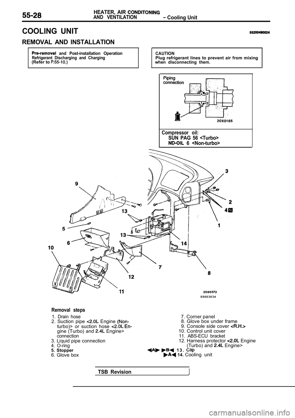
COOLING UNIT
REMOVAL AND INSTALLATION
and Post-installation OperationRefrigerant Discharging and Charging(Refer to
CAUTIONPlug refrigerant lines to prevent air from mixingwhen disconnecting them.
Compressor oil:
SUN PAG 56
6
0 0 0 0 3 6 3 4
Removal steps
1. Drain hose2. Suction pipe Engine
turbo)> or suction hose gine (Turbo) and Engine>connection3. Liquid pipe connection4. O-ring5. Stopper
6. Glove box7. Corner panel
8. Glove box under frame
9. Console side cover
10. Control unit cover11. ABS-ECU bracket12. Harness protector Engine
(Turbo) and Engine> 1 3 . 14. Cooling unit
TSB Revision