Page 369 of 2103

E N G I N E O V E R H A U L Flywheel
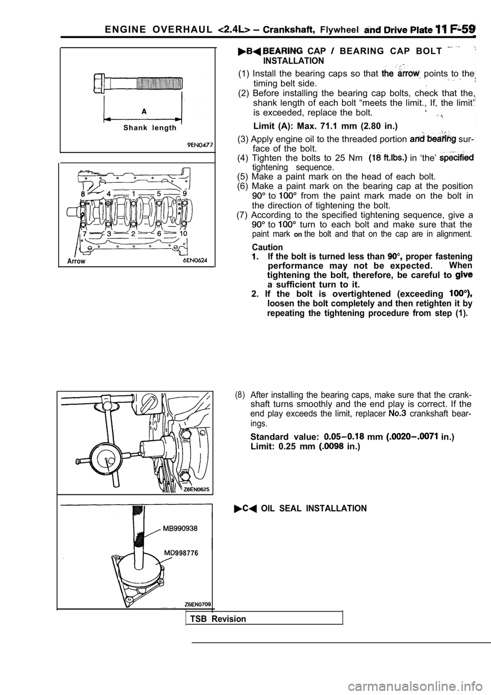
S h a n k l e n g t h
Arrow
CAP B E A R I N G C A P B O L T
INSTALLATION
(1) Install the bearing caps so that points to the
timing belt side.
(2) Before installing the bearing cap bolts, check that the,
shank length of each bolt “meets the limit., If, th e limit’
is exceeded, replace the bolt.
Limit (A): Max. 71.1 mm (2.80 in.)
(3) Apply engine oil to the threaded portion
sur-
face of the bolt.
(4) Tighten the bolts to 25 Nm
in ‘the’
tightening sequence.
(5) Make a paint mark on the head of each bolt.
(6) Make a paint mark on the bearing cap at the pos ition
to from the paint mark made on the bolt in
the direction of tightening the bolt.
(7) According to the specified tightening sequence, give a
to turn to each bolt and make sure that the
paint mark onthe bolt and that on the cap are in alignment.
Caution
If the bolt is turned less than proper fastening
performance may not be expected.When
tightening the bolt, therefore, be careful to
a sufficient turn to it.
2. If the bolt is overtightened (exceeding
loosen the bolt completely and then retighten it by
repeating the tightening procedure from step (1).
(8)After installing the bearing caps, make sure that t he crank-
shaft turns smoothly and the end play is correct. I f the
end play exceeds the limit, replacer crankshaft bear-
ings.
Standard value: mm in.)
Limit: 0.25 mm
in.)
OIL SEAL INSTALLATION
998776
TSB Revision
Page 371 of 2103

ENGINE OVERHAUL Crankshaft, Flywheel and, . .
INSPECTION11300880103
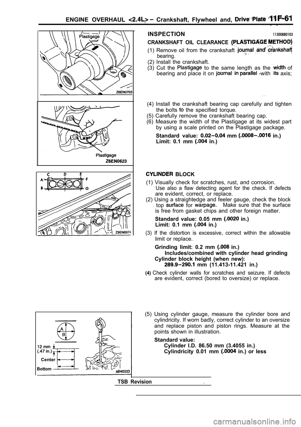
CRANKSHAFT OIL CLEARANCE
(1) Remove oil from the crankshaft
bearing.
(2) Install the crankshaft.
(3) Cut the
to the same length as the of
bearing and place it on
-with axis;
(4) Install the crankshaft bearing cap carefully an d tighten
the bolts
the specified torque.
(5) Carefully remove the crankshaft bearing cap.
(6) Measure the width of the Plastigage at its wide st part
by using a scale printed on the Plastigage package.
Standard value:
mm in.)
Limit: 0.1 mm
in.)
BLOCK
(1) Visually check for scratches, rust, and corrosi on.
Use also a flaw detecting agent for the check. If d efects
are evident, correct, or replace.
(2) Using a straightedge and feeler gauge, check th e block
top for Make sure that the surface
is free from gasket chips and other foreign matter.
Standard value: 0.05 mm
in.)
Limit: 0.1 mm
in.)
(3) If the distortion is excessive, correct within the allowable
limit or replace.
Grinding limit: 0.2 mm
in.)
Includes/combined with cylinder head grinding
Cylinder block height (when new):
mm (11.413-11.421 in.)
(4)Check cylinder walls for scratches and seizure. If defects
are evident, correct (bored to oversize) or replace.
Center
Bottom
TSB Revision
(5) Using cylinder gauge, measure the cylinder bore and
cylindricity. If worn badly, correct cylinder to an oversize
and replace piston and piston rings. Measure at the
points shown in illustration.
Standard value: Cylinder I.D. 86.50 mm (3.4055 in.)
Cylindricity 0.01 mm
in.) or less
Page 372 of 2103
ENGINE OVERHAUL Crankshaft, Flywheel ‘and ‘Drive Plate
Thrustdirection
B O R I N G C Y L I N D E R
(1) Oversize pistons to be used should determined on
the basis of the largest bore
Piston size identification
Size mark
0.50
1
NOTE
Size mark is stamped on piston top.
(2)
outside diameter of piston to be used.
it in thrust direction as shown.
(3) Based on measured piston O.D. calculate boring
Boring finish dimension
between piston O.D.
0.02 mm in.) (honing margin)
(4) Bore all cylinders to calculated boring finish dimension.
Caution
To prevent distortion that may result from temperat ure
rise during honing, bore cylinders, working from
2to No. 4 to No. 1 to No. 3.
(5) Hone to final finish dimension
clearance
between piston O.D. and cylinder).
(6) Check clearance between- piston and cylinder.
Clearance between piston and cylinder:
mm in.)
NOTE
When boring cylinders, finish all of four cylinders to same
Do not bore only one cylinder to an
TSB Revision
Page 375 of 2103
ENGINE LUBRICATION Service
DraingasketOil pan side
Engine (Non-turbo)>
If these oils are not available, an API classificat
ion
or can be used.’ . .
ON-VEHICLE
ENGINE OIL
.
Pull out the oil dipstick slowly and check that the oil
is within the marks on the oil dipstick.
2.Check that the oil is dirty, that there is
no coolant or gasoline mixed in, ‘and that it has, sufficient
viscosity.
ENGINE OIL REPLACEMENT
After warming up the engine, remove the oil filler cap.
2.Remove the drain plug to allow the engine oil to drain.
3.Replace the drain plug gasket with a new one and ti ghten
the drain plug.
Page 376 of 2103
![MITSUBISHI SPYDER 1990 Service Repair Manual 12-4 L U B R I C A T I O N
EngineI
Turbo
4. Supply new engine oil through the oil filler.Engine oil total quantity:[including oil filter and oil cooler]
Engine (Non-turbo) arid MITSUBISHI SPYDER 1990 Service Repair Manual 12-4 L U B R I C A T I O N
EngineI
Turbo
4. Supply new engine oil through the oil filler.Engine oil total quantity:[including oil filter and oil cooler]
Engine (Non-turbo) arid](/manual-img/19/57345/w960_57345-375.png)
12-4 L U B R I C A T I O N
EngineI
Turbo
4. Supply new engine oil through the oil filler.Engine oil total quantity:[including oil filter and oil cooler]
Engine (Non-turbo) arid
4 . 3 (4 q t s . )
Engine (Turbo)>
4.4
(4.6 qts.)
5. Start and run the engine a
minutes.
6.Stop the engine and check the engine oil level is w ithin
the level range indicated on the oil dipstick.
.
NOTE
may be used for operation in very cold weather
areas where the lowest ambient temperature is below
OIL REPLACEMENT
1. Remove the engine oil filler cap.
2.Remove the engine oil drain plug, and drain out the engine
o i l .
3.Remove the engine oil filter by using the oil filter wrench.
4.Clean the oil filter mounting, surface of the oil f ilter bracket.
5. Coat engine oil to the O-ring of’new filter: .
6.Screw on the oil filter by hand until it touchesthe surface
of the flange and then tighten it with. the filter wrench:
etc.
Engine (Turbo) Engine>
lFor One full turn or 14 Nm
lFor or 17 Nm (12
E n g i n e ( N o n - t u r b o ) >
lFor 090: turn or 21 Nm (15
7. Add new engine oil through the oil filter.
8. Start and run engine and check for engine oil le aks.
9. After stopping engine, check oil level and reple nish as
necessary.
TSB Revision
Page 377 of 2103
ENGINE LUBRICATION Oil Cooler
ENGINE OIL COOLER 12100130117
REMOVAL AND INSTALLATION
Operationl Engine Coolant Draining(Refer to GROUP 00 Maintenance
Engine oil
Engine Oil Checking and Supplying
2
Removal steps
1. Oil filter
2. Water hose connection
3. Oil cooler bolt
4. Engine oil cooler
Oil filter bracket
Stopper
Engine oil cooler
INSTALLATION SERVICE POINT
ENGINE OIL COOLER INSTALLATION
the stopper into the groove of the oil filter bracket,
and then tighten the oil cooler bolt.
TSB Revision
Page 378 of 2103
12-6ENGINE LUBRICATION Engine Oil Cooler
INSPECTION
lCheck the water for cracks, clogging, or
deterioration.
lCheck the oil cooler bolt clogging deformation.
Revision
Page 381 of 2103

FUEL
INJECTION
CONTENTS
FUEL INJECTION (MFI)
ENGINE (NON-TURBO)> . . . . . . . 3
Relay (ASD Relay) and Fuel ‘Relay
Check.. . . . . . . . . . . . . . . . . . . . . . . . . . , . . . . .128
Throttle Position Sensor Check. . . . . . . . . . .
129
GENERAL INFORMATION . . . . . . . . . . . . . . . . 3ON-VEHICLE SERVICE. . . . . . . . . . . . . . . .119
INJECTOR. . . . . . . . . . . . . . . . . . . . . . . . . . . .134Fuel Pressure Test . . . . . . . . . . . , . . . . . . . . .121
ON-VEHICLE INSPECTION OF
COMPONENTS . . . . . . . . . . . . . . . . . . . . . .
Component Location. . . . . . . . . . . . . . . . . . . 124
Electric EGR Transducer Solenoid Check
. . . . . . . . . . . . . . . . . . . . . . . . . . . . . . .. . . . . . . . .133
Engine Coolant Temperature Sensor Check
. . . . . . . . . . . . . . . . . . . . . . . . . . . . . . . . . . . . . . . .129
Evaporative Emission Purge Solenoid
C h e c k . . . . . . . . . . . . . . . . . . . . . . . . . . . . . . . . . . 1 3 3
Heated Oxygen Sensor Check . . . . . . . . . . . 13 0
Idle Air Control Motor (Stepper Motor)
Check . . . . . . . . . . . . . . . . . . . . . . . . . . . . . . . . . .132
Injector Check . . . . . . . . . . . . . . . . . . . . . . . . . .132
Intake Air Temperature Sensor Check . . . . 128 Fuel Pump Connector Disconnection
(How to Reduce Fuel Line Pressure) . . . . . 123
Throttle Body Minimum Air
Check . . . 110 ,
SEALANT. . . . . . . . . . . . . . . . . . . . . . . . . . . . . . .
SERVICE SPECIFICATIONS . . . . . . . . . . . . . . 6
SPECIAL TOOLS . . . . . . . . . . . . . . .
. . . . . 7,
THROTTLE BODY . . . . . . . . . . . . . . . . .
TROUBLESHOOTING. . . . . . . . . . . . . . . . 6
CONTINUED ON NEXT PAGE