1990 MITSUBISHI SPYDER check engine
[x] Cancel search: check enginePage 68 of 2103
ENGINE On-vehicle Service
pump pulley
Cranksh
pulley
pulley
a
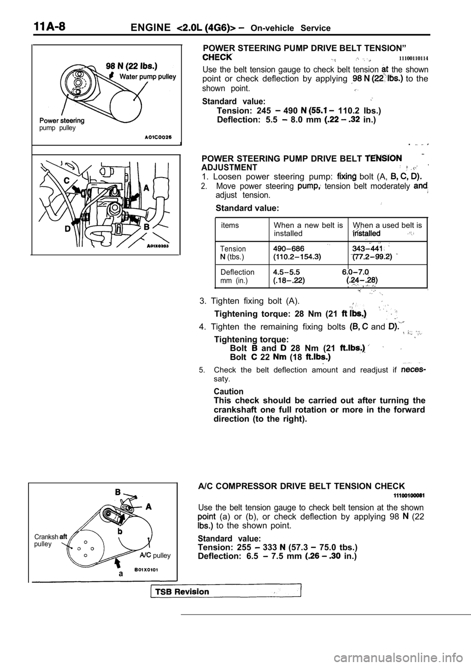
POWER STEERING PUMP DRIVE BELT TENSION”
11100110114
Use the belt tension gauge to check belt tension the shown
point or check deflection by applying to the
shown point.
Standard value:
Tension: 245 490 110.2 Ibs.)
Deflection: 5.5
8.0 mm in.)
.
POWER STEERING PUMP DRIVE BELT
ADJUSTMENT
1. Loosen power steering pump: bolt (A,
2.Move power steering tension belt moderately
adjust tension.
Standard value:
items
Tension
(tbs.)
Deflection
mm (in.)
When a new belt is When a used belt is installed
,,
3. Tighten fixing bolt (A).
Tightening torque: 28 Nm (21
4. Tighten the remaining fixing bolts and
Tightening torque:
Bolt and 28 Nm (21
Bolt 22 (18
5.Check the belt deflection amount and readjust if
saty.
Caution
This check should be carried out after turning the
crankshaft one full rotation or more in the forward
direction (to the right).
A/C COMPRESSOR DRIVE BELT TENSION CHECK
Use the belt tension gauge to check belt tension at the shown
(a) or (b), or check deflection by applying 98 (22
to the shown point.
Standard value:
Tension: 255 333 (57.3 75.0 tbs.)
Deflection: 6.5
7.5 mm in.)
Page 69 of 2103
ENGINE On-vehicle
A/C COMPRESSOR DRIVE BELT TENSION ADJUSTMENT
1. Loosen tension pulley fixing bolt A.
2. Adjust belt tension with adjusting bolt B.
Standard value:
Items
Tension
(Ibs.)
Deflection
When a new belt isWhen a used belt is
installedinstalled
382-411255-333
6.5-7.5
3. Tighten fixing nut A.
Tightening torque: 23-26 Nm
4.Check the belt deflection and readjust if neces-
sary.
Caution
This check should be carried out after turning the
crankshaft one full rotation or more in the forward
direction (to the right).
IGNITION TIMING CHECK
1.Before inspection and adjustment set vehicle in the follow-
ing condition.
lEngine coolant temperature:
lLights, electric cooling fan and all accessories: OFF
lTransaxle: Neutral (P range on vehicles with
2. Turn the ignition switch to OFF and connect the scan
tool to the data link connector.
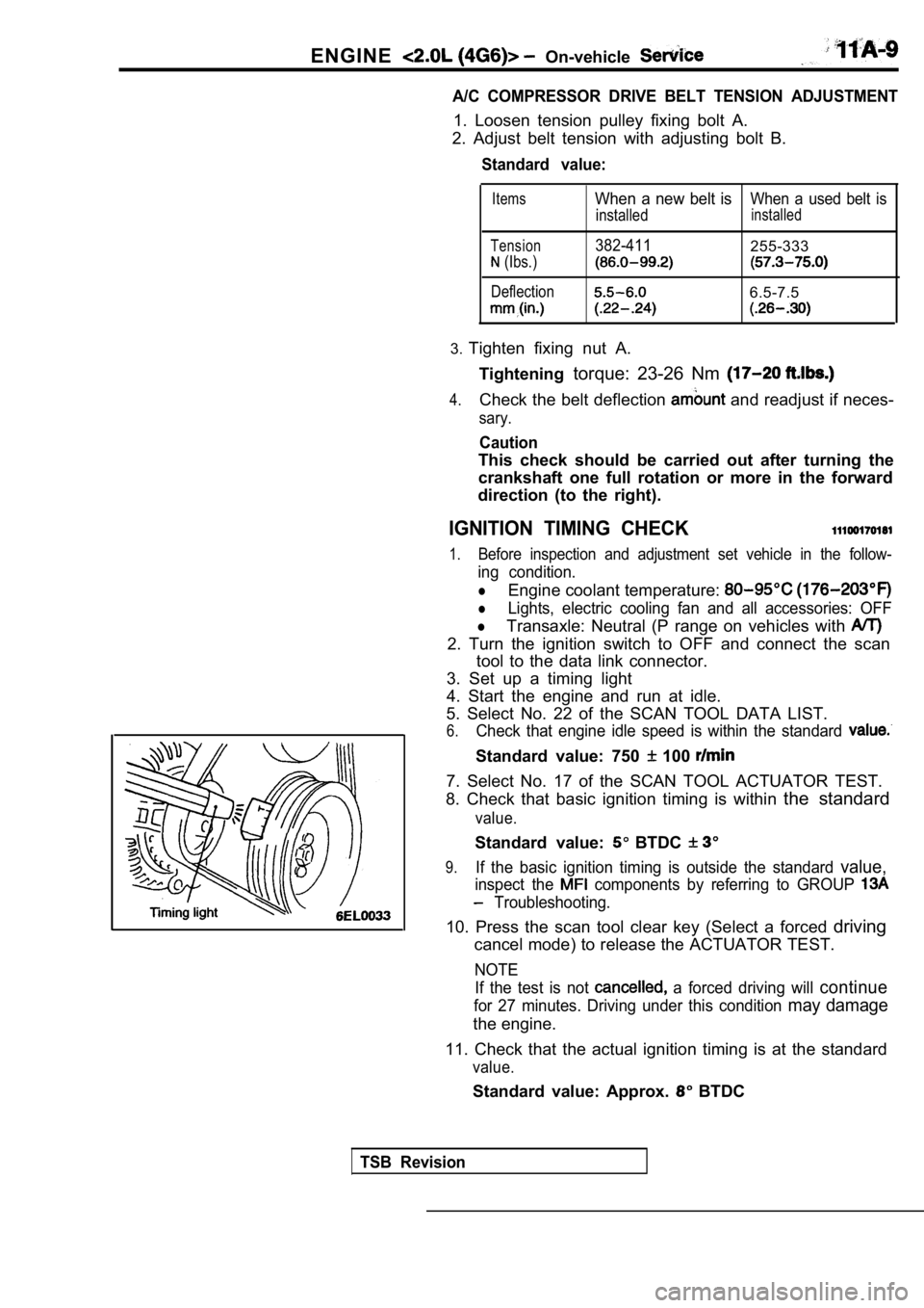
3. Set up a timing light
4. Start the engine and run at idle.
5. Select No. 22 of the SCAN TOOL DATA LIST.
6.Check that engine idle speed is within the standard
Standard value: 750 100
7. Select No. 17 of the SCAN TOOL ACTUATOR TEST.
8. Check that basic ignition timing is within the standard
value.
Standard value: BTDC
9.If the basic ignition timing is outside the standar d value,
inspect the components by referring to GROUP
Troubleshooting.
10. Press the scan tool clear key (Select a forced driving
cancel mode) to release the ACTUATOR TEST.
NOTE
If the test is not
a forced driving will continue
for 27 minutes. Driving under this condition may damage
the engine.
11. Check that the actual ignition timing is at the standard
value.
Standard value: Approx. BTDC
TSB Revision
Page 70 of 2103
ENGINE On-vehicle Service
NOTE
1.Ignition timing is variable within about even under
operating.
2. And it is automatically further advanced by abou t
from BTDC at higher altitudes.
CURB IDLE SPEED CHECK
1. Before inspection and adjustment, set vehicles in the
following condition.
lEngine coolant temperature:
lLights, electric cooling fan and all accessories: OFF
lTransaxle: Neutral (P range on vehicles with
2. Turn the ignition switch to OFF and connect the scan
tool to the data link connector.
3. Select No. 17 of the SCAN TOOL ACTUATOR TEST.
4. Check the basic ignition timing.
Standard
BTDC
5. Run the engine at idle for 2 minutes.
6. Select No. 22 of the SCAN TOOL DATA LIST.
7. Check the curb idle speed.
Standard value: 750
100
NOTE
The idle speed is controlled automatically by the i dle air
control system.
8. If the idle speed is outside the standard value, inspect
the components by referring to GROUP Trou-
bleshooting.
IDLE MIXTURE CHECK .
1.Before inspection, set in following
lEngine coolant temperature:
lLights, electric cooling fan all
lTransaxle: Neutral (P range on
2. Turn the ignition switch to OFF and, connect the scan
tool to the data link ,
3. Select No. 17 of the SCAN TOOL
4.Check that the basic ignition
value.
Standard value: BTDC
5. Run the engine 2,500 for 2 minutes.
6. Set the CO, HC tester.
7. Check the CO contents and the HC contents, at id le.
Standard value: CO contents: 0.5% or less
HC contents: 100 rpm or less
Revision
Page 71 of 2103

ENGINE On-vehicle
8. If the standard value is exceeded, check the following
items:
l Diagnostic output
l Closed-loop control (When the closed-loop control
is carried out normally, the output signal of the h eated
oxygen sensor repeats between and
,000 at idle.)
l Fuel pressure
I n j e c t o r
lIgnition coil, spark plug cable, spark plug
lEGR system and the EGR valve leak
l Evaporative emission control system
Compression pressure
NOTE
Replace the catalyst whenever the
HC contents do not remain inside the standard value .
(even though the result of the inspection is
all items.).
C O M P R E S S I O N
CHECK
1.Before inspection, check that the engine-oil, start er
battery are normal. Also, set the to the
condition:
lEngine coolant temperature:
lLights, electric cooling fan and all accessories: O FF
lTransaxle: Neutral (P range on vehicles with
2. Disconnect the spark plug cables.
3. Remove all of the spark plugs.
4.
5.
Disconnect the crankshaft position sensor connector .
NOTE
Doing this will prevent the engine control unit fro m carrying
out ignition and fuel injection.
Cover the spark plug hole with a shop towel etc., a nd
after the engine has been cranked, check that no fo reign
material is adhering to the shop towel.
TSB Revision
Page 72 of 2103
ENGINE On-vehicle
Caution
1.Keep away from the spark plug hole when crank-
ing.
2. If compression is measured with water, oil, fuel,
etc., that has come from cracks inside the cylinder ,
these materials will become heated and will gush
out from the spark plug hole, which is dangerous.
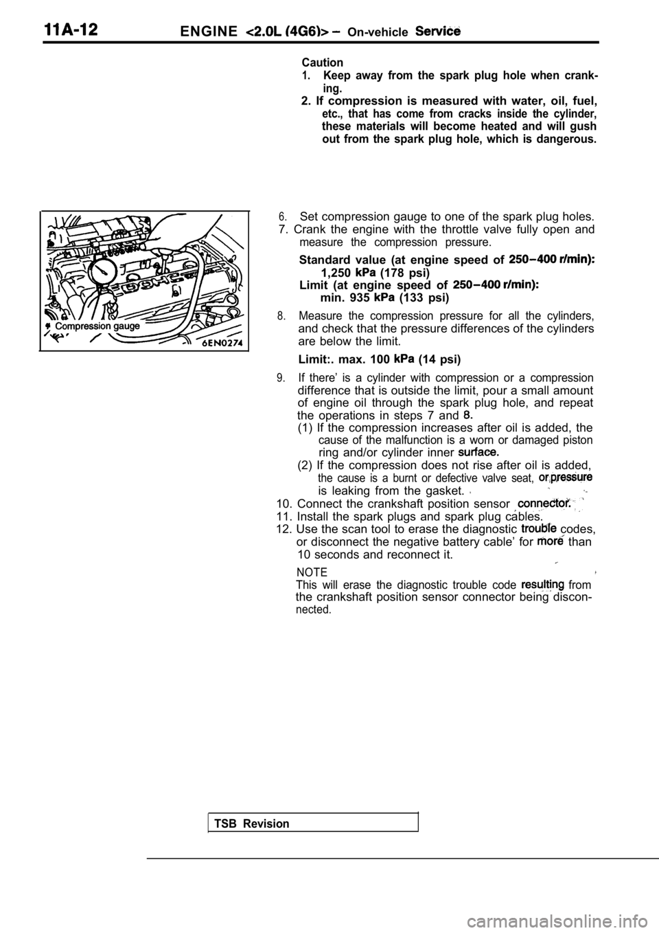
6.Set compression gauge to one of the spark plug hole s.
7. Crank the engine with the throttle valve fully o pen and
measure the compression pressure.
Standard value (at engine speed of
1,250 (178 psi)
Limit (at engine speed of
min. 935 (133 psi)
8.Measure the compression pressure for all the cylind ers,
and check that the pressure differences of the cylinders
are below the limit.
Limit:. max. 100
(14 psi)
9.If there’ is a cylinder with compression or a compr ession
difference that is outside the limit, pour a small amount
of engine oil through the spark plug hole, and repe at
the operations in steps 7 and
(1) If the compression increases after oil is added , the
cause of the malfunction is a worn or damaged pisto n
ring and/or cylinder inner
(2) If the compression does not rise after oil is added,
the cause is a burnt or defective valve seat,
is leaking from the gasket.
10. Connect the crankshaft position sensor
11. Install the spark plugs and spark plug cables.
12. Use the scan tool to erase the diagnostic
codes,
or disconnect the negative battery cable’ for
than
10 seconds and reconnect it.
NOTE
This will erase the diagnostic trouble code from
the crankshaft position sensor connector being disc on-
nected.
TSB Revision
Page 73 of 2103
ENGINE On-vehicle Service
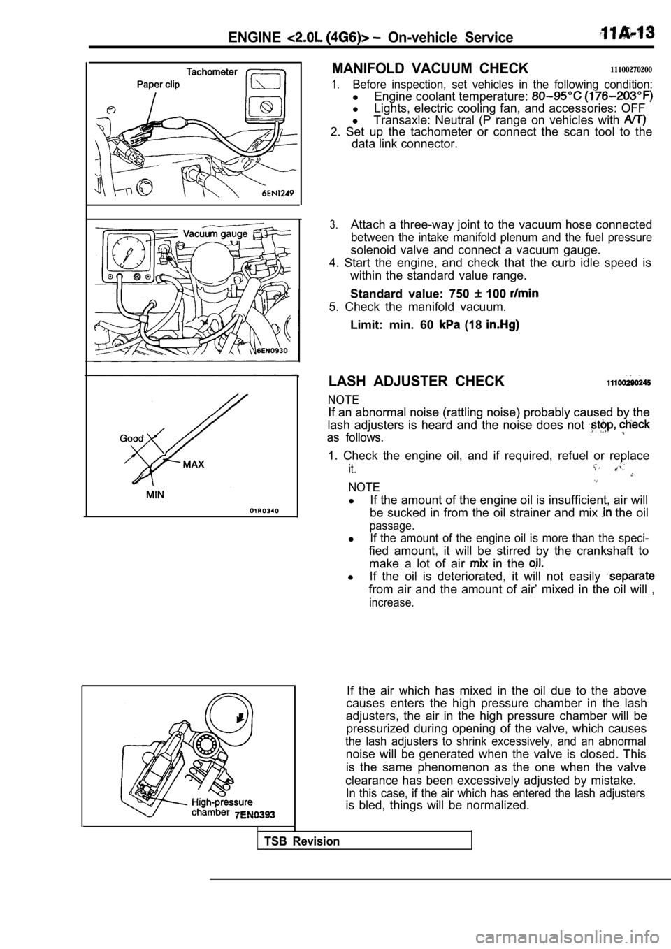
MANIFOLD VACUUM CHECK11100270200
1.Before inspection, set vehicles in the following condition:
lEngine coolant temperature:
lLights, electric cooling fan, and accessories: OFF
l Transaxle: Neutral (P range on vehicles with
2. Set up the tachometer or connect the scan tool t o the
data link connector.
3.Attach a three-way joint to the vacuum hose connect ed
between the intake manifold plenum and the fuel pressure
solenoid valve and connect a vacuum gauge.
4. Start the engine, and check that the curb idle s peed is
within the standard value range.
Standard value: 750
100
5. Check the manifold vacuum.
Limit: min. 60
(18
LASH ADJUSTER CHECK
NOTE
NOTE
If an abnormal noise (rattling noise) probably caus ed by the
If an abnormal noise (rattling noise) probably caus ed by the
lash adjusters is heard and the noise does not
lash adjusters is heard and the noise does not
as follows.
as follows.
1. Check the engine oil, and if required, refuel or replace
it.
NOTE
lIf the amount of the engine oil is insufficient, ai r will
be sucked in from the oil strainer and mix
the oil
passage.
lIf the amount of the engine oil is more than the sp eci-
fied amount, it will be stirred by the crankshaft to
make a lot of air
in the
l If the oil is deteriorated, it will not easily
from air and the amount of air’ mixed in the oil wi ll ,
increase.
If the air which has mixed in the oil due to the ab ove
causes enters the high pressure chamber in the lash
adjusters, the air in the high pressure chamber wil l be
pressurized during opening of the valve, which caus es
the lash adjusters to shrink excessively, and an abnormal
noise will be generated when the valve is closed. T his
is the same phenomenon as the one when the valve
clearance has been excessively adjusted by mistake.
In this case, if the air which has entered the lash adjusters
is bled, things will be normalized.
TSB Revision
Page 74 of 2103
ENGINE On-vehicle Service
Timing belt side
.
2.Start the engine and perform gentle racing* several times
(less than times.)
If the abnormal noise stops by racing, the air is b led
from the high pressure chamber of the lash adjusters
and the function of the lash adjusters is normalized.
After raising the engine speed from idling to 3000
gradually (in 30 seconds), drop the
ally (in 30 seconds) to idling.
NOTE
lIf the vehicle is parked on a slope for the oil
in the lash adjusters will be decreased ‘andairmay
enter the high pressure chamber when the
is started.
lAfter the vehicle is parked for long, air may enter
the high pressure chamber because the, oil in the
oil passage will be gone and, it will take a time b efore
the oil is supplied to the lash adjusters.
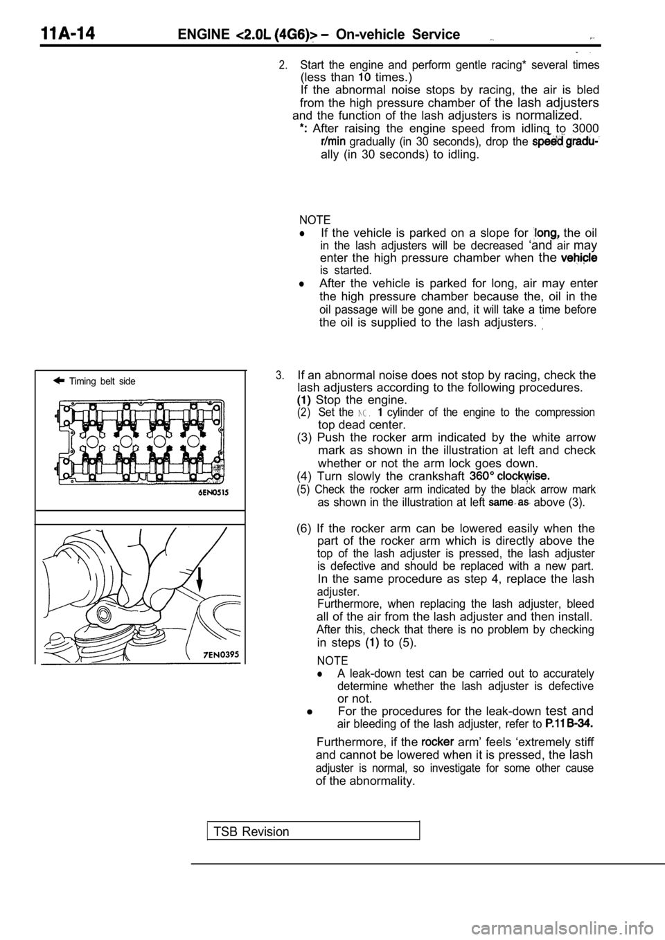
3.If an abnormal noise does not stop by racing, check the
lash adjusters according to the following procedure s.
Stop the engine.
(2)Set the NG. cylinder of the engine to the compression
top dead center.
(3) Push the rocker arm indicated by the white arro w
mark as shown in the illustration at left and check
whether or not the arm lock goes down.
(4) Turn slowly the crankshaft
(5) Check the rocker arm indicated by the black arr ow mark
as shown in the illustration at left above (3).
(6) If the rocker arm can be lowered easily when th e
part of the rocker arm which is directly above the
top of the lash adjuster is pressed, the lash adjus ter
is defective and should be replaced with a new part .
In the same procedure as step 4, replace the lash
adjuster.
Furthermore, when replacing the lash adjuster, bleed
all of the air from the lash adjuster and then install.
After this, check that there is no problem by check ing
in steps to (5).
NOTE
lA leak-down test can be carried out to accurately
determine whether the lash adjuster is defective
or not.
l For the procedures for the leak-down test and
air bleeding of the lash adjuster, refer to
Furthermore, if the arm’ feels ‘extremely stiff
and cannot be lowered when it is pressed, the lash
adjuster is normal, so investigate for some other c ause
of the abnormality.
TSB Revision
Page 79 of 2103
ENGINE -‘Engine Assembly
COMPRESSOR
Disconnect the compressor connector and remove the
compressor from the compressor bracket
the hose
attached.
NOTE
Place the removed A/C compressor in a where it will
not be a hindrance when removing ‘and installing th e engine
assembly, and tie it with a cord:
Caution
Do not bend the joint the A/C hose and the
pipe by force.
ENGINE MOUNT BRACKET ASSEMBLY
REMOVAL
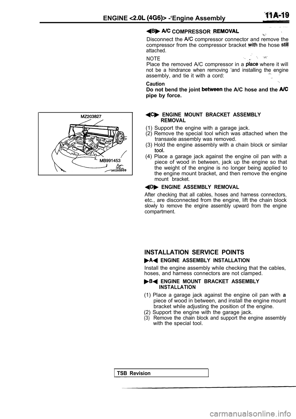
(1) Support the engine with a garage jack.
(2) Remove the special tool which was attached when the
transaxle assembly was removed.
(3) Hold the engine assembly with a chain block or similar
(4) Place a garage jack against the engine oil pan with a
piece of wood in between, jack up the engine so tha t
the weight of the engine is no longer being applied to
the engine mount bracket, and then remove the engin e
mount bracket.
ENGINE ASSEMBLY REMOVAL
After checking that all cables, hoses and harness connectors,
etc., are disconnected from the engine, lift the chain block
slowly to remove the engine assembly upward from th e engine
compartment.
INSTALLATION SERVICE POINTS
ENGINE ASSEMBLY INSTALLATION
Install the engine assembly while checking that the cables,
hoses, and harness connectors are not clamped.
ENGINE MOUNT BRACKET ASSEMBLY
INSTALLATION
(1) Place a garage jack against the engine oil pan with a
piece of wood in between, and install the engine mo unt
bracket while adjusting the position of the engine.
(2) Support the engine with the garage jack.
(3)Remove the chain block and support the engine assem bly
with the special tool.
TSB Revision