Page 246 of 2103
11E N G I N E O V E R H A U L Oil Pan and Oil’
Revision
0057
(1) Apply Loctite 51817 to oil pump as shown in the figure.
Install oil-ring into the counter bore on the oil p ump body
discharge passage.
(2) oil pump slowly onto crankshaft until seated to
engine ‘block. Tighten fasteners to 23 Nm (17
(3) Install new seal by using Tool
(4) Place seal into opening with seal spring toward the inside
engine. Install seal until flush with cover.
(5) Install crankshaft sprocket using
bolt, washer and thrust bearing, from Special ‘Tool Kii
and Tool
,
.
(6) Install oil pick-up tube.
Page 255 of 2103
piston,
ENGINE
(1) Before installing pistons and connecting rod assemblies
into the bore, be sure that compression ring gaps a re
staggered so that neither is in line with oil ring rail gap.
Front of engine
(2) Before installing the ring compressor, make sur e the
ring expander ends are butted and the rail
as shown in the figure.
.
(3) Immerse the piston head and rings in clean engine oil,
slide the ring compressor, over the piston. Be sure that
position of rings does not change during this opera tion.
(4) The arrow should face toward the front of the engine.
Install the pistons.
(5) Rotate crankshaft so that the connecting journal is
on the center of the cylinder bore. rod and piston
assembly into cylinder bore and guide rod over the crank-
shaft journal.
TSB Revision
Page 260 of 2103

piston,
ENGINE OVERHAUL Cylinder Block
CONNECTING BEARING
(1) Place a piece of Plastigage across the, width of
bearing in the cap 6.35
mm off center and away -from the hole.
suspect areas can be checked, by placing in
the suspect area.
(2) Before assembling the rod with in place;
‘the crankshaft must be rotated the connecting rod
being checked starts moving toward the top of the e ngine.,
Only then should the cap be and torqued
to the specification.
Do not rotate the crankshaft while assembling the cap
or the Plastigage may be smeared, giving inaccurate re-
sults.
(3) Remove the bearing cap and compare the width of the
flattened Plastigage with the metric scale provided on
the package.
Standard value: mm in.)
Limit: 0.075 mm
in.)
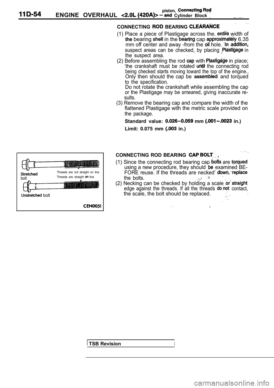
bolt
Threads are not straight on line
Threads are straight
line,
bolt
CONNECTING ROD BEARING ,
(1) Since the connecting rod bearing cap are
using a new procedure, they should examined BE-
FORE reuse. If the threads are necked’
the bolts.
(2) Necking can be checked by holding a scale
edge against the threads. If all the threads contact,
the scale, the bolt should be replaced. .
,
TSB RevisionI
Page 265 of 2103
ENGINE OVERHAUL
2
Oil seal
95059
seal
new front seal into opening with seal spring towards
the inside of engine. seal by using Tool
until flush with oil pump cover.
Caution
if burr or scratch is present on the crankshaft edge
(chamfer), with 400 grit sand paper to prevent
seal damage during of new seal.
NOTE
When installing seal, no lube on seal is needed.
Tool on crankshaft. This is a
pilot tool with a magnetic base.
seal over pilot tool. Make sure you can read
the words THIS SIDE OUT on seal. Pilot tool should
remain on crankshaft during installation of seal.
the seal into the block using Special Tool
and handle until the tool bottoms out against
the block.
Caution
If the seal is driven into the block past flush, this
may cause an oil leak.
TSB Revision
Page 280 of 2103

ENGINEOn-vehicle
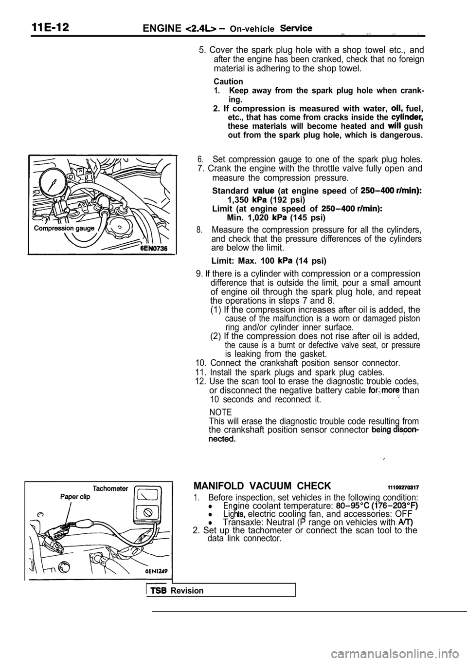
5. Cover the spark plug hole with a shop towel etc., and
after the engine has been cranked, check that no foreign
material is adhering to the shop towel.
Caution
1.Keep away from the spark plug hole when crank-
ing.
2. If compression is measured with water, fuel,
etc., that has come from cracks inside the
these materials will become heated and gush
out from the spark plug hole, which is dangerous.
6.Set compression gauge to one of the spark plug hole s.
7. Crank the engine with the throttle valve fully open and
measure the compression pressure.
Standard (at engine speed of
1,350 (192 psi)
Limit (at engine speed of
Min. 1,020 (145 psi)
8.Measure the compression pressure for all the cylind ers,
and check that the pressure differences of the cyli nders
are below the limit.
Limit: Max. 100 (14 psi)
9. there is a cylinder with compression or a compression
difference that is outside the limit, pour a small amount
of engine oil through the spark plug hole, and repe at
the operations in steps 7 and 8.
(1) If the compression increases after oil is added , the
cause of the malfunction is a worn or damaged pisto n
ring and/or cylinder inner surface.
(2) If the compression does not rise after oil is added,
the cause is a burnt or defective valve seat, or pr essure
is leaking from the gasket.
10. Connect the crankshaft position sensor connecto r.
11. Install the spark plugs and spark plug cables.
12. Use the scan tool to erase the diagnostic troub le codes,
or disconnect the negative battery cable than
10 seconds and reconnect it.
NOTE
This will erase the diagnostic trouble code resulting from
the crankshaft position sensor connector
MANIFOLD VACUUM CHECK
1.Before inspection, set vehicles in the following co ndition:
lEn
lLig electric cooling fan, and accessories: OFF
ine coolant temperature:
lTransaxle: Neutral (P range on vehicles with
2. Set up the tachometer or connect the scan tool t o the
data link connector.
Revision
Page 287 of 2103
Engine Assembly
I N S T A L L A T I O N
ENGINE INSTALLATION
Install the engine while checking
hoses, and harness connectors are not clamped.
MOUNT BRACKET ASSEMBLY
I N S T A L L A T I O N
(1) Place a garage jack against the engine oil pan a
piece of wood in between, and install the engine mo unt
bracket assembly while adjusting the position of th e
en-
gine.
(2) Support the engine with the garage jack.
(3)Remove the chain block and support the engine assem bly
with the special tool.
Engine sideEngine
Arro
Engine
mount
bracket(4) Align the notches on the stopper with the engin e mount
bracket with the arrow facing toward the shown
direction. Then install the stopper.
assembly
HIGH-PRESSURE FUEL HOSE CONNECTION
When connecting the high-pressure fuel hose to the fuel rail,
apply a small amount of clean engine oil to the hos e union
and then insert, being careful not to damage the O-ring.
Caution
Do not let engine oil get the fuel
.
TSB Revision
Page 308 of 2103

ENGINE Timing Belt
TIMING BELT REMOVAL,,
Caution
If timing belt “B” is to be reused, use
it with an arrow on its flat side indicating the tu rning
direction (to the right).
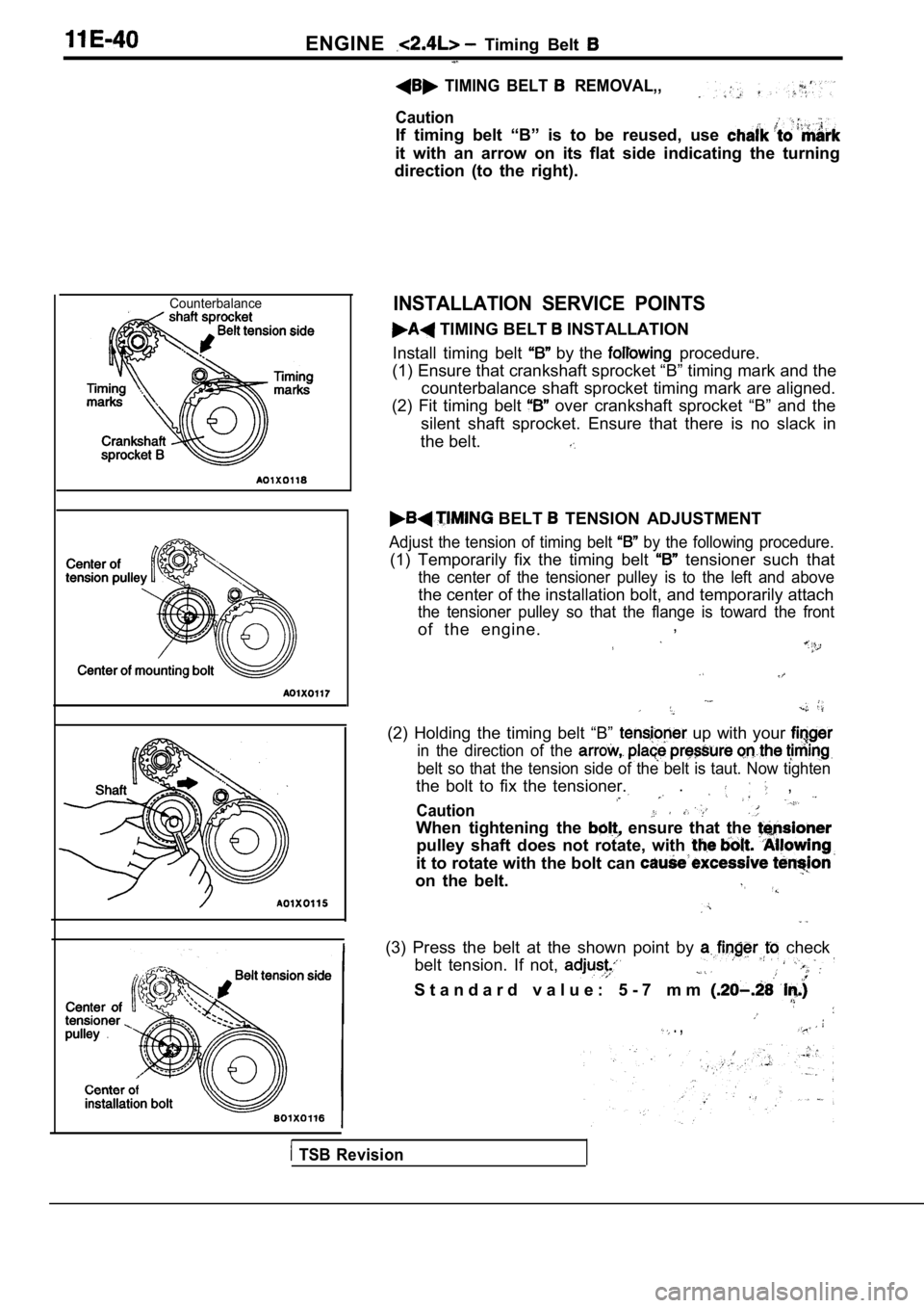
CounterbalanceINSTALLATION SERVICE POINTS
TIMING BELT INSTALLATION
Install timing belt
by the procedure.
(1) Ensure that crankshaft sprocket “B” timing mark and the
counterbalance shaft sprocket timing mark are align ed.
(2) Fit timing belt
over crankshaft sprocket “B” and the
silent shaft sprocket. Ensure that there is no slac k in
the belt.
BELT TENSION ADJUSTMENT
Adjust the tension of timing belt by the following procedure.
(1) Temporarily fix the timing belt tensioner such that
the center of the tensioner pulley is to the left a nd above
the center of the installation bolt, and temporarily attach
the tensioner pulley so that the flange is toward t he front
of the engine.,
(2) Holding the timing belt “B” up with your
in the direction of the
belt so that the tension side of the belt is taut.
Now tighten
the bolt to fix the tensioner.. ,
Caution
When tightening the ensure that the
pulley shaft does not rotate, with
it to rotate with the bolt can
on the belt.
(3) Press the belt at the shown point by check
belt tension. If not,
S t a n d a r d v a l u e : 5 - 7 m m
. ,
TSB Revision
Page 345 of 2103
E N G I N E O V E R H A U L Cylinder Head and Valves
color
REMOVAL SERVICE
PRECAUTION FOR PARTS
Keep removed parts in order according to cylinder
and intake/exhaust.
CYLINDER HEAD BOLTS
Using the special tool, loosen head bolts. Loosen
evenly, little by little.
LOCK REMOVAL
Store removed valves, springs and other parts, tagg ed to
indicate their cylinder No. and location for reasse mbly.
STEM SEAL REMOVAL
Do not reuse valve stem seal.
INSTALLATION SERVICE POINTS
VALVE STEM SEAL INSTALLATION
(1) Install’ the valve spring seat.
(2) The special tool must be’used install
seal. Improper installation in oil leaking
the valve guide.
Caution
Do not reuse the valve stem seal.
VALVE SPRINGS INSTALLATION
Direct the valve spring end with identification col or end toward
the spring retainer.
TSB Revision