Page 1502 of 2103

PROPELLER
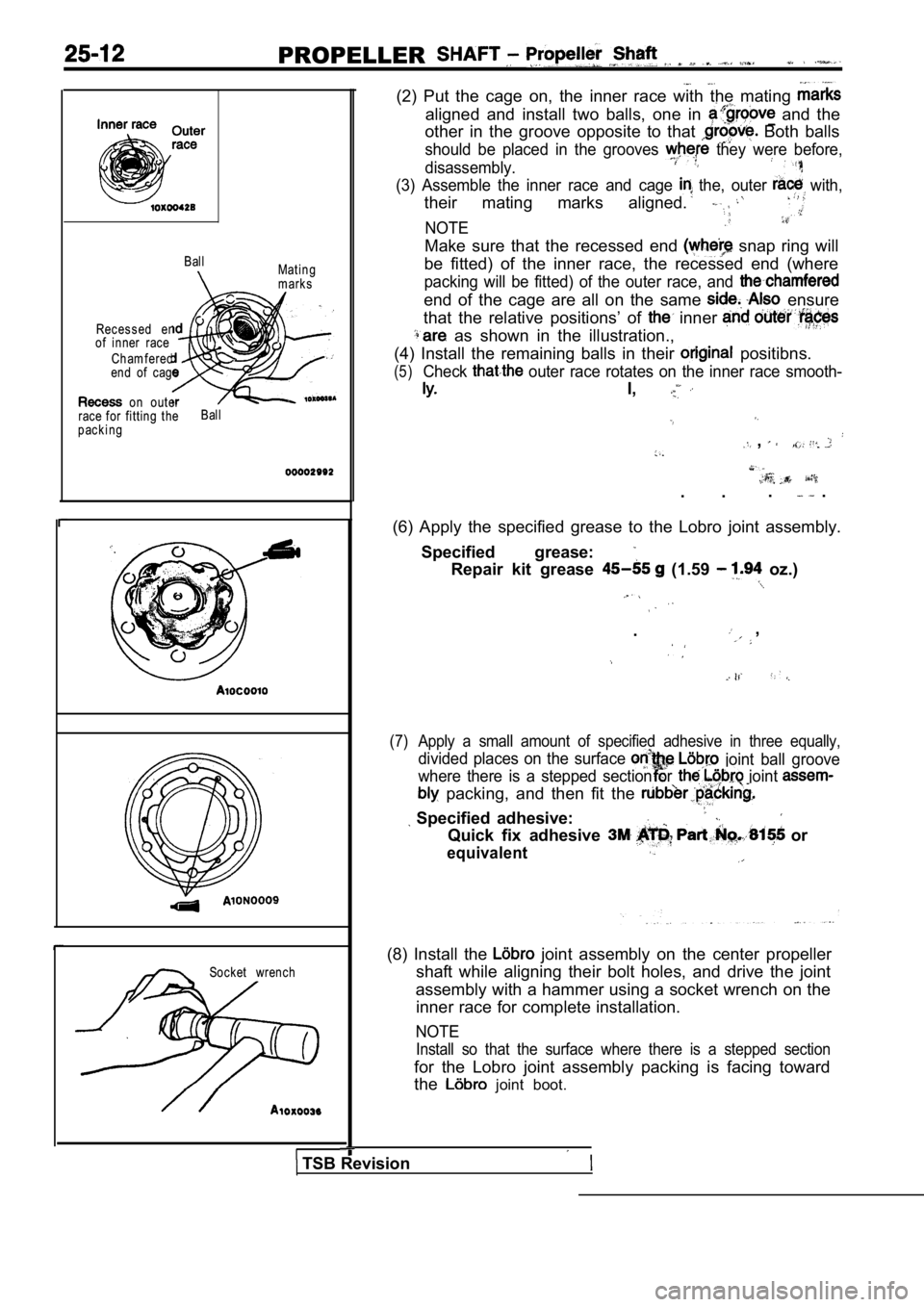
BallMating
marks
Rec es s ed end
of inner race
Chamferedend of cage
on outer
race for fitting the Ball
packing
Socket wrench
(2) Put the cage on, the inner race with the mating
aligned and install two balls, one in and the
other in the groove opposite to that
Both balls
should be placed in the grooves they were before,
disassembly.
(3) Assemble the inner race and cage the, outer with,
their mating marks aligned.
NOTE
Make sure that the recessed end snap ring will
be fitted) of the inner race, the recessed end (whe re
packing will be fitted) of the outer race, and
end of the cage are all on the same ensure
that the relative positions’ of
inner
as shown in the illustration.,
(4) Install the remaining balls in their
positibns.
(5)Check outer race rotates on the inner race smooth-
I,
,
. . . .
(6) Apply the specified grease to the Lobro joint a ssembly.
Specified grease:
Repair kit grease (1.59 oz.)
. ,
(7) Apply a small amount of specified adhesive in th ree equally,
divided places on the surface joint ball groove
where there is a stepped section or
joint
packing, and then fit the
Specified adhesive:
Quick fix adhesive or
equivalent
(8) Install the joint assembly on the center propeller
shaft while aligning their bolt holes, and drive th e joint
assembly with a hammer using a socket wrench on the inner race for complete installation.
NOTE
Install so that the surface where there is a steppe d section
for the Lobro joint assembly packing is facing towa rd
the
joint boot.
TSB Revision
Page 1594 of 2103
32-4P O W E R P L A N T M O U N T
REMOVAL AND INSTALLATION
OperationJack Up the Engine and Transaxle Assembly Until Thereis no Weight on the Engine Mount Bracket Insulator.
Engine (Non-turbo)>
86
63
9871
Removal steps
1. Enaine mount insulator mounting
2. Engine mount bracket 3. Engine mount stopper
Engine sideEngine
mount Engine
mount
stopper
______ .bracket
Engine (Turbo) and Engine>
87 .
,
9871 85
INSTALLATION POINT
ENGINE MOUNT
Align the notches on the stopper with the engine bracket
with the arrow mark facing toward the shown
install the stopper.
,
INSPECTION
lCheck each insulator for cracks or damage.
lCheck each bracket for deformations or damage.
TSB Revision
Page 1596 of 2103
32-6
Transaxlemount stopper
POWER PLANT MOUNT Transaxle . ,
Transaxle side l TRANSAXLE MOUNT
Align the notches on the stopper with the transaxle mount
bracket with the arrow mark facing toward the
Then install the stopper. ,
INSPECTION
lCheck each insulator for cracks or damage.
lCheck each bracket for
.
TSB Revision
Page 1605 of 2103
FRONT SUSPENSION On-vehicle Service
NOTE .
1.If the toe-in is not standard value, adjust the
toe-in by undoing, the and the left arid
tie rod by the same amount (in opposite direc-
tions).
2. The toe will move out as the is turned
toward the front of the vehicle and the
is turned toward the rear of the vehicle.
STEERING ANGLE
Standard value:
Inner wheel
(AWD)
Outer wheel
(FWD)
(AWD)
CAMBER
Standard value:
(Vehicles with lbinch wheels)
(Vehicles with wheels),AWD
CASTER
Standard value:
NOTE
1.Camber and caster are preset at the’factory and can not
be adjusted.
2. If camber is not within the standard value, chec k
replace bent or damaged parts.
3. For vehicles with aluminum type’ wheels, attach the
camber/caster/kingpin gauge to the drive shaft by ‘using
the special tool. Tighten the special tool, to the same
torque
Nm as drive shaft
nut.
Caution
Never subject the wheel bearings to the load
when the drive shaft nuts are loosened.
TSB Revision
Page 1652 of 2103
4 SYSTEM Service
Pad
indicator
Brake disc
BRAKE PAD CHECK AND . .
REPLACEMENT
brake ‘pads have wear that contact
disc when ‘the brake pad 2
The wear indicators a to warn
to have the pads replaced h&e
checked.
1.Check. brake pad.
port.
Standard’ 10 mm
,
Limit: 2.0 mm in.)
Caution
When the limit is pads on
both the left and be replaced
as a set.
2. If there is, a significant in the
thicknesses of the pads on the left and right sides,
the sliding condition- of -the
pin guide pin.
2. g u i d e c a l i p e r t h e ”
assembly toward, the inside of the wheel well
from the lock Support it
Caution
Donot wipe off the special guide
pin or allow it to
Page 1659 of 2103

BASIC BRAKE SYSTEM
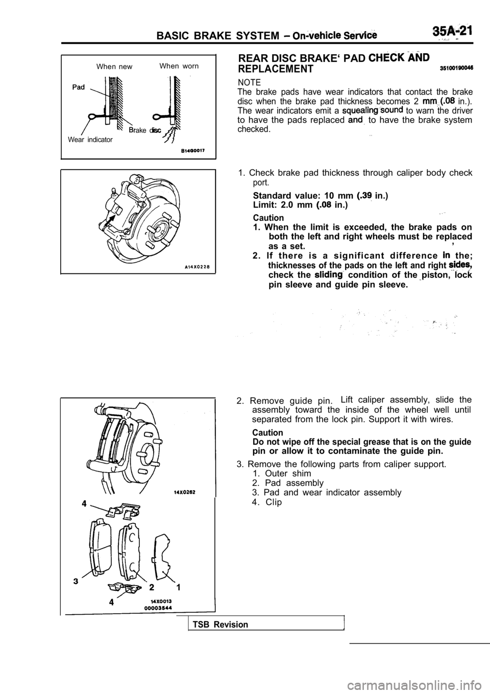
When newWhen worn
rake disc
Wear indicator
1 REAR DISC BRAKE‘ PAD
REPLACEMENT
NOTE
The brake pads have wear indicators that contact th
e brake
disc when the brake pad thickness becomes 2
in.).
The wear indicators emit a
to warn the driver
to have the pads replaced to have the brake system
checked.. .
1. Check brake pad thickness through caliper body c heck
port.
Standard value: 10 mm in.)
Limit: 2.0 mm
in.)
Caution
1. When the limit is exceeded, the brake pads on
both the left and right wheels must be replaced
as a set. ,
2 . I f t h e r e i s a s i g n i f i c a n t d i f f e r e n c e
the;
thicknesses of the pads on the left and right
check the condition of the piston, lock
pin sleeve and guide pin sleeve.
2. Remove guide pin. Lift caliper assembly, slide the
assembly toward the inside of the wheel well until
separated from the lock pin. Support it with wires.
Caution Do not wipe off the special grease that is on the g uide
pin or allow it to contaminate the guide pin.
3. Remove the following parts from caliper support. 1. Outer shim
2. Pad assembly
3. Pad and wear indicator assembly
4. Clip
TSB Revision
Page 1771 of 2103
PARKING BRAKES, parking Brake Brake>
Shoe
Paint
Shoe-to-anchor spring (rear)
Forward
R E M O V A L
REAR BRAKE.
Remove the rear brake assembly and ‘support.
or similar.
,
SHOE HOLD-DOWN
Extend the shoe assembly, and remove the shoe
h o l d - d o w n c u p .
INSTALLATION
ADJUSTER
Install the adjuster so that the shoe adjusting-bol t of left hand
wheel ‘is attached towards the front the’ vehicle, and the
shoe adjusting bolt of right hand wheel is towards the rear
of the vehicle.
SPRING INSTALLATION
The the respective shoe-to-anchor different,
so the, spring in the figure has been
NOTE
The shows the left wheel; for the right the
position is symmetrical.
TSB Revision
Page 1773 of 2103
PARKING BRAKES
BRAKE ASSEMBLY
Remove the rear brake assembly and support it with wire
or. similar.
Shoe
Shoe-to-anchor spring(rear)
Forward
SHOE
-Extend the shoe and lining assembly, and remove th e shoe
hold-down cup.
INSTALLATION SERVICE POINTS
ADJUSTER INSTALLATION
the adjuster so that the shoe adjusting bolt of left hand
wheel is attached towards the front of the vehicle, and the
shoe adjusting bolt of right hand wheel is towards the rear
of the vehicle.
SHOE-TO-ANCHOR SPRING INSTALLATION
The load on the respective shoe-to-anchor springs i s different,
so the spring in the figure has been painted.
NOTE
The figure shows the left wheel; for the right
the position
is symmetrical.
TSB Revision