Page 1908 of 2103
42-84BODY Sunroof
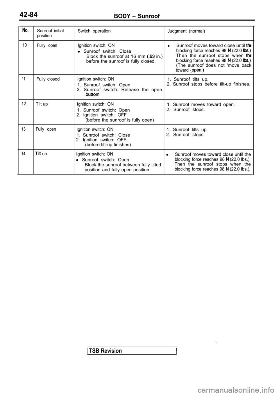
No.Sunroof initial
position Switch operation
Judgment (normal)
10Fully open
11Fully closedIgnition switch: ON
lSunroof moves toward close until
l
Sunroof switch: Closeblocking force reaches 98 (22.0
Block the sunroof at 16 mm in.) Then the sunroof stops when
before the sunroof is fully closed.blocking force reaehes 98 (22.0
(The sunroof does not ‘move back
toward. .
Ignition switch: ON1. Sunroof tilts up.
1. Sunroof switch: Open 2. Sunroof stops before tilt-up finishes.
2. Sunroof switch: Release the open
12Tilt up Ignition switch: ON
1. Sunroof switch: Open
2. Ignition switch: OFF
(before the sunroof is fully open) 1. Sunroof moves toward open.
2. Sunroof stops.
13Fully openIgnition switch: ON
1. Sunroof switch: Close
2. Ignition switch: OFF
(before tilt-up finishes) 1. Sunroof tilts up.
2. Sunroof stops
14 up Ignition switch: ONlSunroof moves toward close until the
l Sunroof switch: Open
blocking force reaches 98 (22.0 Ibs.).
Block the sunroof between fully tilted Then the sunroof stops when the
position and fully open position.blocking force reaches 98 (22.0 Ibs.).
TSB Revision
Page 1912 of 2103
42-88BODY Sunroof
Front
Rear
Sunroof
cable end
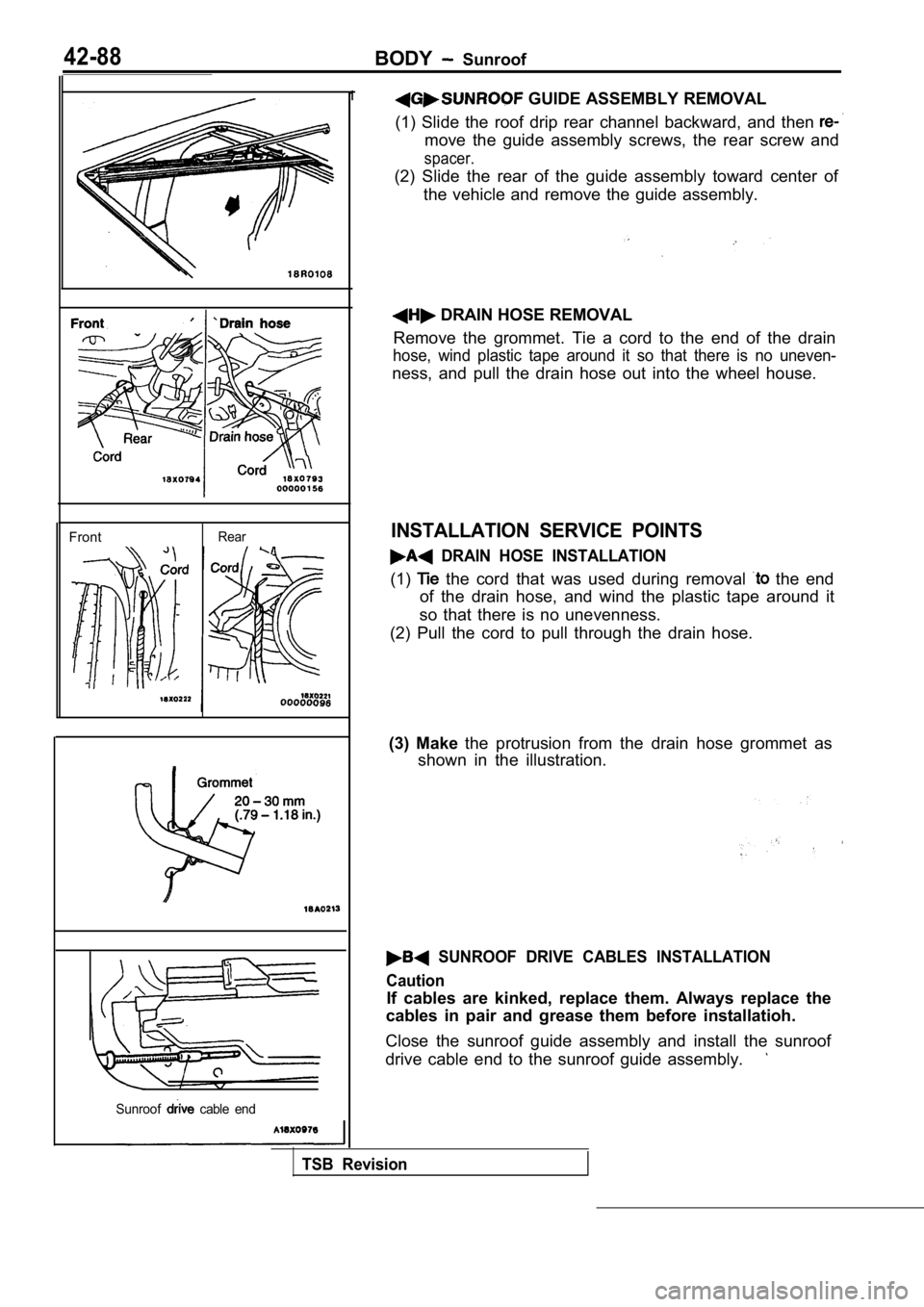
1 GUIDE ASSEMBLY REMOVAL
(1) Slide the roof drip rear channel backward, and then
move the guide assembly screws, the rear screw and
spacer.
(2) Slide the rear of the guide assembly toward cen ter of
the vehicle and remove the guide assembly.
DRAIN HOSE REMOVAL
Remove the grommet. Tie a cord to the end of the dr ain
hose, wind plastic tape around it so that there is no uneven-
ness, and pull the drain hose out into the wheel ho use.
INSTALLATION SERVICE POINTS
DRAIN HOSE INSTALLATION
(1) the cord that was used during removal the end
of the drain hose, and wind the plastic tape around it
so that there is no unevenness.
(2) Pull the cord to pull through the drain hose.
(3) Make the protrusion from the drain hose grommet as
shown in the illustration.
SUNROOF DRIVE CABLES INSTALLATION
Caution
If cables are kinked, replace them. Always replace the
cables in pair and grease them before installatioh.
Close the sunroof guide assembly and install the su nroof
drive cable end to the sunroof guide assembly.
TSB Revision
Page 1927 of 2103
BODY Electric Convertible Top
CONVERTIBLE TOP SWITCH
REMOVAL
42620240012
A N D I N S T A L L A T I O N
NOTE indicates the metal clip position.
Removal steps
1. Stopper 2. Center air outlet assembly3. Convertible top switch
REMOVAL SERVICE POINT
AIR OUTLET ASSEMBLY REMOVAL
Using the pry tool, carefully pry the assembly out of the
INSTALLATION SERVICE POINT
CENTER AIR OUTLET ASSEMBLY
INSTALLATION
(1) Turn the cool air bypass lever of the center ai r outlet
fully downward.
(2) Pull the cool air bypass damper lever on the heater unit
side fully toward you, then attach the cable to the pin
of the
(3) Push the outer cable in the direction of the ar row so
there is no looseness, then secure it with the clip.
TSB Revision
Page 1939 of 2103
E X T E R I O R Moldings:
Masking tape
Fishing line
Double-sided tape
Adhesive
desin spatula
REMOVAL SERVICE
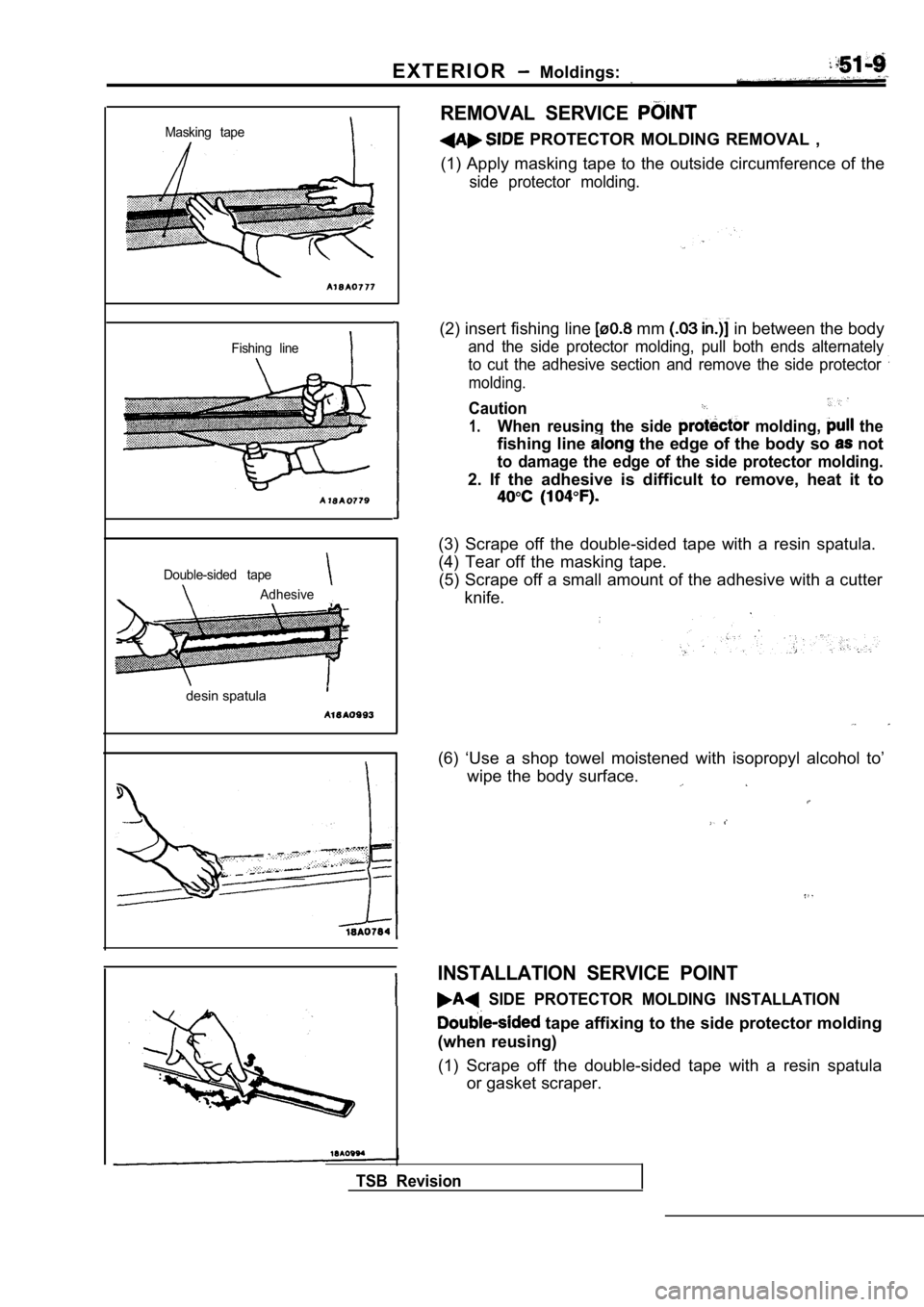
PROTECTOR MOLDING REMOVAL ,
(1) Apply masking tape to the outside circumference of the
side protector molding.
(2) insert fishing line mm in between the body
and the side protector molding, pull both ends alternately
to cut the adhesive section and remove the side pro tector
molding.
Caution
1.When reusing the side molding, the
fishing line the edge of the body so not
to damage the edge of the side protector molding.
2. If the adhesive is difficult to remove, heat it to
(3) Scrape off the double-sided tape with a resin spatula.
(4) Tear off the masking tape. (5) Scrape off a small amount of the adhesive with a cutter
knife.
(6) ‘Use a shop towel moistened with isopropyl alco hol to’
wipe the body surface.
INSTALLATION SERVICE POINT
SIDE PROTECTOR MOLDING INSTALLATION
tape affixing to the side protector molding
(when reusing)
(1) Scrape off the double-sided tape with a resin s patula
or gasket scraper.
TSB Revision
Page 1940 of 2103
EXTERIOR Moldings
Primer
(2) a shop towel moistened isopropyl. alcohol
wipe the molding surface.
(3) Remove
small portion of the residual adhesive.
not remove all
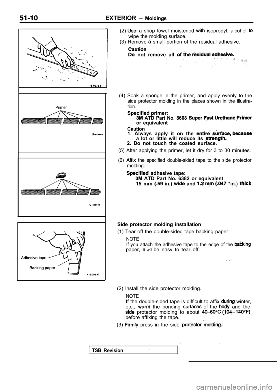
(4) Soak a sponge in the primer, and apply evenly t o the
side protector molding in the places shown in the illustra-
tion.
Specified primer:
ATD Part No. 8608
or equivalent
Caution1. Always apply it on the
a lot or little will reduce its
2. Do not touch the coated surface.
(5) After applying the primer, let it dry for 3 to 30 minutes.
(6) the specified double-sided tape to the side protec tor
molding.
adhesive tape:
ATD Part No. 6382 or equivalent
15 mm
in.) and *in.)
Side protector molding installation
(1) Tear off the double-sided tape backing paper.
NOTE
If you attach the adhesive tape to the edge of the
paper, it will be easy to tear off.
(2) Install the side protector molding.
NOTE
If the double-sided tape is difficult to affix winter,
etc., the bonding of the and the
protector molding to about
before affixing the tape.
(3)
press in the side
TSB Revision
Page 1963 of 2103
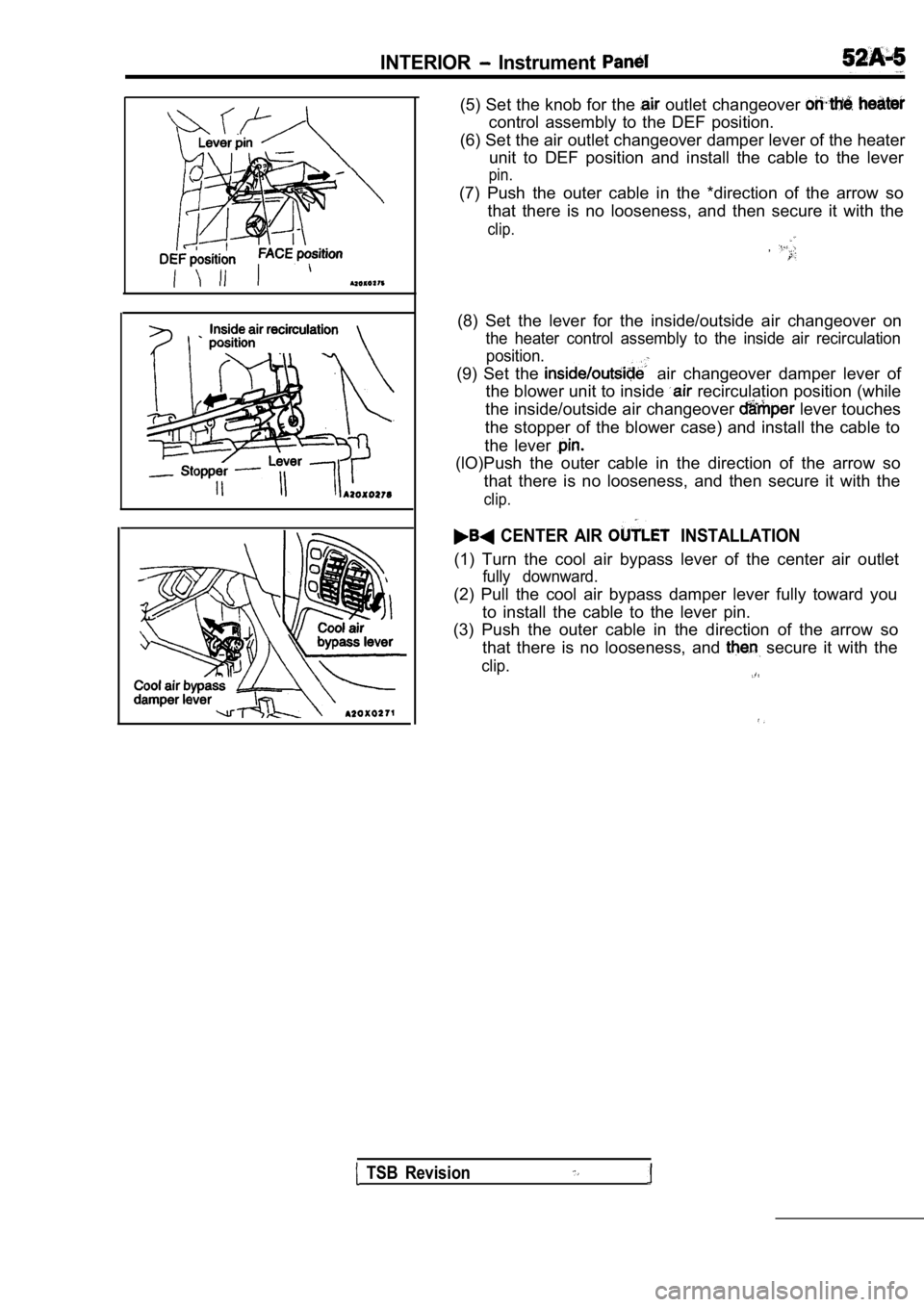
INTERIOR Instrument
(5) Set the knob for the outlet changeover
control assembly to the DEF position.
(6) Set the air outlet changeover damper lever of t he heater
unit to DEF position and install the cable to the l ever
pin.
(7) Push the outer cable in the *direction of the a rrow so
that there is no looseness, and then secure it with the
clip.
,
(8) Set the lever for the inside/outside air changeover on
the heater control assembly to the inside air recirculation
position.
(9) Set the air changeover damper lever of
the blower unit to inside
recirculation position (while
the inside/outside air changeover
lever touches
the stopper of the blower case) and install the cab le to
the lever
(lO)Push the outer cable in the direction of the ar row so
that there is no looseness, and then secure it with the
clip.
CENTER AIR INSTALLATION
(1) Turn the cool air bypass lever of the center ai r outlet
fully downward.
(2) Pull the cool air bypass damper lever fully toward you
to install the cable to the lever pin.
(3) Push the outer cable in the direction of the ar row so
that there is no looseness, and
secure it with the
clip.
TSB Revision
Page 1973 of 2103
INTERIOR Headlining
,
00003744
NOTE Metal clip position
Rear roof rail
Removal steps
1. assembly
2. holder
3. Rear roof rail trim
4. Sunroof inner weatherstrip 5. Sunroof switch cover
6. Sunroof switch panel
7. Headlining
Tab
REMOVAL SERVICE POINT
DOME LIGHT ASSEMBLY REMOVAL
Press and pull the tab downward to remove the dome light
assembly.
INSTALLATION SERVICE POINT
SUNROOF INNER WEATHERSTRIP
INSTALLATION
Install the sunroof inner weatherstrip with its adhered joint
located toward the rear of the vehicle and on its c enter line.
Adhered joint
Front of vehicle
Page 1976 of 2103
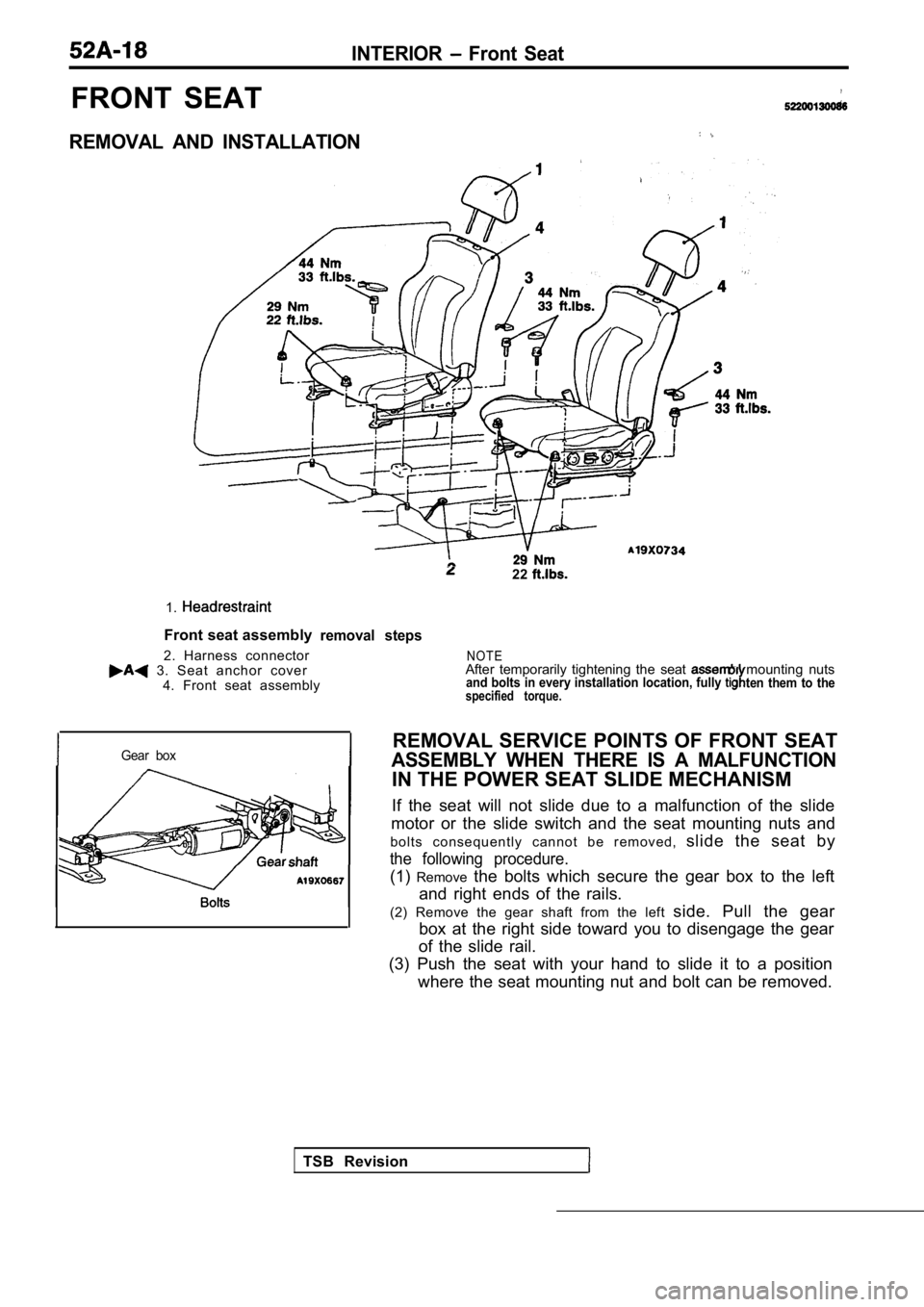
INTERIOR Front Seat
FRONT SEAT
REMOVAL AND INSTALLATION
1.
Front seat assembly
2. Harness connector
3. Seat anchor cover 4. Front seat assembly
22
removal steps
Gear box
TSB Revision
N O T EAfter temporarily tightening the seat mounting nutsand bolts in every installation location, fully ten them to thespecified torque.
REMOVAL SERVICE POINTS OF FRONT SEAT
ASSEMBLY WHEN THERE IS A MALFUNCTION
IN THE POWER SEAT SLIDE MECHANISM
If the seat will not slide due to a malfunction of the slide
motor or the slide switch and the seat mounting nut s and
b o l t s c o n s e q u e n t l y c a n n o t b e r e m o v e d , slide the seat by
the following procedure.
(1)Remove the bolts which secure the gear box to the left
and right ends of the rails.
(2) Remove the gear shaft from the left side. Pull the gear
box at the right side toward you to disengage the g ear
of the slide rail.
(3) Push the seat with your hand to slide it to a p osition
where the seat mounting nut and bolt can be removed .