Page 1781 of 2103

STEERING On-vehicle”
TSB Revision
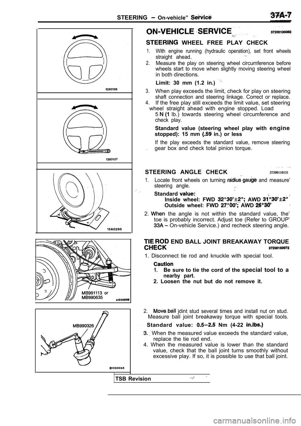
WHEEL FREE PLAY CHECK
1.With engine running (hydraulic operation), set front wheels
straight ahead.
2.Measure the play on steering wheel circumference be fore
wheels start to move when slightly moving steering wheel
in both directions.
Limit: 30 mm (1.2 in.)
3.When play exceeds the limit, check for play on steering
shaft connection and steering linkage. Correct or replace.
4.If the free play still exceeds the limit value, set steering
wheel straight ahead with engine stopped. Load
5
(1 lb.) towards steering wheel circumference and
check play.
Standard value (steering wheel play with engine
stopped): 15 mm
in.) or less
If the play exceeds the standard value, remove stee ring
. .gear box and check total pinion torque.
STEERING ANGLE CHECK
37200110131
1.Locate front wheels on turning and measure’
steering angle.
Standard
Inside wheel: FWD AWD
Outside wheel: FWD AWD
2. the angle is not within the standard value, the’
toe is probably incorrect. Adjust toe (Refer to GRO UP’
On-vehicle Service.) and recheck steering angle.
END BALL JOINT BREAKAWAY TORQUE
1. Disconnect tie rod and knuckle with special tool .
1.Be sure to tie the cord of the special tool to a
nearby part.
2. Loosen the nut but do not remove it.
2. jdint stud several times and install nut on stud.
Measure ball joint breakaway torque with special to ols.
Standard value:
Nm (4-22
When the measured value exceeds the standard value ,
replace the tie rod end.
4. When the measured value is lower than the standa rd
value, check that the ball joint turns smoothly wit hout
excessive play. If so, it is possible to use that b all joint.
Page 1804 of 2103
STEERING Power Steering Gear Box
Bellows band
Concave
PINION TORQUE ADJUSTMENT
(1) Position rack at its center. Tighten support
to 15 Nm (11
(2) in neutral position, clockwise one
seconds with special tool., rack
cover and adjust torque to the. standard
(3) Using the special tools, rotate the pinion gear at the
of one rotation in approximately 4 to 6 seconds to
the total pinion torque.
Standard value:
(6-12
[Change in torque: 0.4 Nm (3
Caution
1.When adjusting, set standard value at high-
est value.
2.Assure no ratcheting or operating,
rack towards the shaft direction.
NOTE
When it cannot be adjusted the specified return]
angle, check rack support cover components or repla ce.
(4) After adjusting, lock rack cover with lock nut.
ROD INSTALLATION
.
After installing tie rod to rack, fold
to tie rod notch.
end (2 locations)
ii
BELLOWS BAND INSTALLATION
(1) Touch pliers against the of the
band and the band.
TSBRevision
Page 1807 of 2103
STEERING Power Steering Oil Pump
INSTALLATION POINT
OIL PUMP ASSEMBLY
‘For the with air conditioning, install the oil pump
assembly to the bracket so that it faces toward
vehicle
front. Then use the air coriditioning tension
adjust
the belt tension..
37300530043
�Check the drive-belt for cracks
�Check the pulley, assembly for uneven rotation.
TSB Revision
Page 1814 of 2103
STEERING Power Steering Pump Engine (Turbo) and Engine>
Suction
REMOVAL SERVICE POINT
SUCTION’ HOSE/PRESSURE HOSE
Caution
Generator is below the oil pump,
with a shop towel before removing of, the ‘hoses.
INSTALLATION SERVICE POINT
PRESSURE HOSE INSTALLATION
Connect the pressure hose so that its notch part co ntacts
the suction connector.
INSPECTION
l Check the drive-belt for
lCheck the pulley assembly for rdtation.
TSB RevisionI
Page 1820 of 2103
STEERING Power Steering Hoses Engine .
White line
REMOVAL POINT
PRESSURE HOSE REMOVAL
Caution
A/C compressor is below the oil pump, so coverthe
compressor with a shop towel before removing-any
INSTALLATION SERVICE POINT
PRESSURE HOSE INSTALLATION
When the pressure hose is installed, align the white line on
the
hose with the white line on the pressure tube
so that together they form a straight line.
Revision
Page 1822 of 2103

STEERING Power Steering Hoses Engine (Turbo) and Engine>
REMOVAL SERVICE
BRAKE FLUID RESERVOIR ASSEMBLY
REMOVAL
Disconnect the brake fluid level sensor connector and
the brake fluid reservoir assembly from the dash panel with
the hose still attached.
NOTE
Place the removed reservoir assembly in a place whe re it
will not be a hindrance when removing and installin g the
power steering gear box, and tie it with a cord.
CLUTCH FLUID RESERVOIR ASSEMBLY
REMOVAL
Remove the clutch fluid reservoir assembly from the dash
panel with the hose still attached.
NOTE
Place the removed reservoir assembly in a place whe re it
will not be a hindrance when removing and installin g the
power steering hoses, and tie it with a cord.
A/C COMPRESSOR REMOVAL
Disconnect the A/C compressor connector remove the
compressor from the compressor bracket with the hos e still
attached.
NOTE
Place the removed in a where it will not be a hindrance when
removing and installing the power steering hoses an d tie
it with a cord.
Caution
Do not damage the joint between the A/C hose and the
A/C pipe.
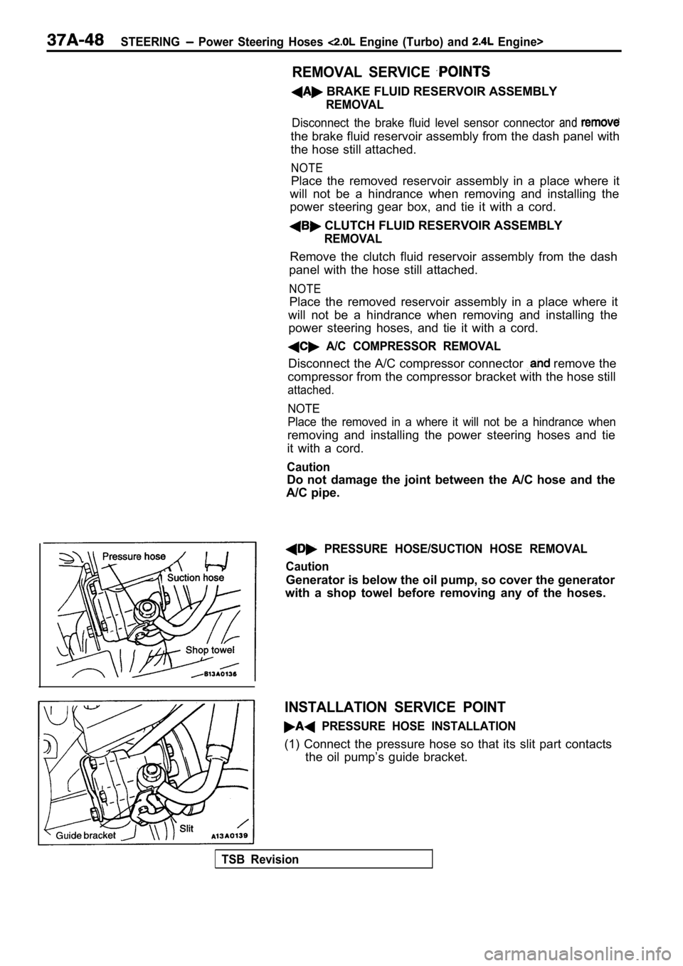
PRESSURE HOSE/SUCTION HOSE REMOVAL
Caution
Generator is below the oil pump, so cover the gener ator
with a shop towel before removing any of the hoses.
INSTALLATION SERVICE POINT
PRESSURE HOSE INSTALLATION
(1) Connect the pressure hose so that its slit part contacts
the oil pump’s guide bracket.
TSB Revision
Page 1879 of 2103
BODY Door
0 0 0 0 0 1 2 4
Front of vehicle
Cover
section
Door inside handle
l i n e
Front of vehicle
R E M O V A L
(A, CLIP REMOVAL
Remove the clip by using a shop and then
the regulator handle.
COVER REMOVAL
Remove the cover mounting screw and cover
by pushing it toward the front of the vehicle to ‘r emove the
clamp section from the door inside handle.
DOOR TRIM REMOVAL
After removing the trim mounting screws and clips, push
the trim to remove it from the door weatherstnp
clips.
INSTALLATION SERVICE
REGULATOR INSTALLATION
(1) Install the escutcheon and the clip to the regulator handle.
(2) Fully close the door glass, and install the reg ulator handle
so that itfaces as shown in the illustration.
,
TSB Revision
Page 1907 of 2103

BODY Sunroof
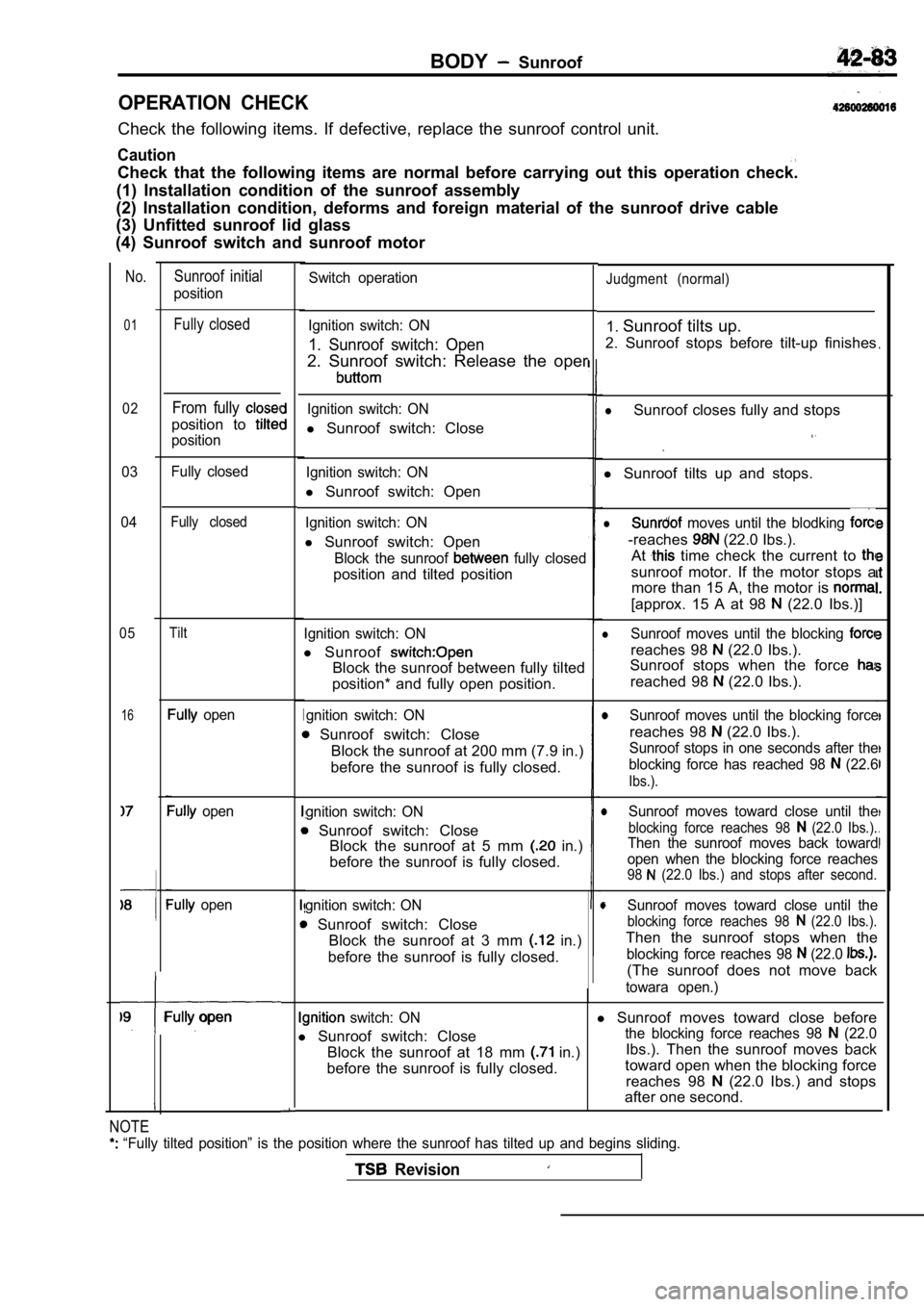
OPERATION CHECK
Check the following items. If defective, replace the sunroof control unit.
Caution
Check that the following items are normal before ca rrying out this operation check.
(1) Installation condition of the sunroof assembly
(2) Installation condition, deforms and foreign mat erial of the sunroof drive cable
(3) Unfitted sunroof lid glass
(4) Sunroof switch and sunroof motor
No.
01
02
03
04
05
16
Sunroof initial
position
Fully closed
From fully
position to
position
Fully closed
Fully closed
Tilt
open
open
open
Fully open
Ignition switch: ON
l Sunroof switch: Close
lSunroof closes fully and stops
Ignition switch: ON
l Sunroof switch: Open l
Sunroof tilts up and stops.
Ignition switch: ON
l Sunroof switch: Open
Block the sunroof fully closed
position and tilted position
l moves until the blodking
-reaches (22.0 Ibs.).
At
time check the current to
sunroof motor. If the motor stops a more than 15 A, the motor is
[approx. 15 A at 98 (22.0 Ibs.)]
Ignition switch: ON
l Sunroof
Block the sunroof between fully tilted
position* and fully open position.
lSunroof moves until the blocking
reaches 98 (22.0 Ibs.).
Sunroof stops when the force
reached 98 (22.0 Ibs.).
gnition switch: ON
Sunroof switch: Close
Block the sunroof at 200 mm (7.9 in.)
before the sunroof is fully closed.
ISunroof moves until the blocking force
reaches 98 (22.0 Ibs.).
gnition switch: ON
Sunroof switch: Close Block the sunroof at 5 mm in.)
before the sunroof is fully closed.
Sunroof stops in one seconds after the
blocking force has reached 98
(22.6
Ibs.).
Sunroof moves toward close until the
blocking force reaches 98 (22.0 Ibs.).Then the sunroof moves back toward
open when the blocking force reaches
98 (22.0 Ibs.) and stops after second.
gnition switch: ON
Sunroof switch: Close Block the sunroof at 3 mm
in.)
before the sunroof is fully closed.
Sunroof moves toward close until the
blocking force reaches 98 (22.0 Ibs.).
Then the sunroof stops when the
blocking force reaches 98 (22.0
(The sunroof does not move back
towara open.)
switch: ONl Sunroof moves toward close before
l Sunroof switch: Close
the blocking force reaches 98 (22.0
Block the sunroof at 18 mm in.) Ibs.). Then the sunroof moves back
before the sunroof is fully closed. toward open when the blocking force
reaches 98
(22.0 Ibs.) and stops
after one second.
Switch operationJudgment (normal)
Ignition switch: ON
1. Sunroof switch: Open
2. Sunroof switch: Release the oper
1. Sunroof tilts up.
2. Sunroof stops before tilt-up finishes
.
NOTE
“Fully tilted position” is the position where the sunroof has tilted up and begins sliding.
Revision