Page 855 of 2103
Clutch Release Cylinder
CLUTCH
Engine (Turbo) and Engine>
DISASSEMBLY SERVICE POINT
AND PISTON CAP REMOVAL
Remove the piston from the release cylinder using c ompressed
air.
Caution
1. Cover with shop towel to prevent the piston from
popping out.
2. Apply compressed air slowly to prevent brake flu id
from splashing.
INSPECTION
Check the inner of the release cylinder for
scratches or irregular wear.
l Check the piston cup for scratch or deformation, an d
the lip for wear.
TSB Revision
Page 865 of 2103
MANUAL TRANSAXLE
ENGINE (TURBO) AND ENGINE> Special Tools
SPECIAL TOOLS
ToolTool number and name
Steering linkage puller
GENERAL SERVICE
TOOL
Engine lifter
453
Engine hanger assem-
bly
Plug
193
‘lug
yoke holder
General Service Tool*
Service Tool
TSB Revision
Application
l Tie rod end ball joint knucklel Lateral lower arm ball joinand knuckle disconnectionlCompression lower arm bajoint and knuckle
tion
Supporting the engine assembly
during removal and installation
of the transaxle
Supporting the engine
during removal and installation
of
Preventing foreign substances
from, entering transaxle case
*Use shop towel
foreign substances
entering transfer
of hub
Page 873 of 2103
MANUAL TRANSAXLE
ENGINE (TURBO) AND ENGINE> Transaxle Assembly
TransaxlemountTransaxle side
stopper
Front roll
member
CLUTCH.
Remove the clutch release cylinder without disconne cting
the oil line, and suspend
a nearby “a
etc.
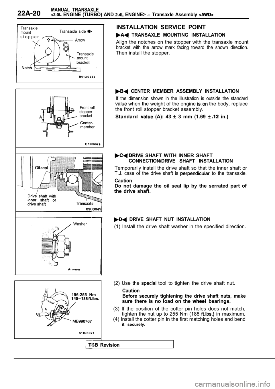
INSTALLATION SERVICE POINT
TRANSAXLE MOUNTING
Align the notches on the stopper with the transaxle mount
bracket with the arrow mark facing toward the shown direction.
Then install the stopper.
CENTER MEMBER
If the dimension shown in the outside the standard
value when the weight of the engine is on the body;, replace
the front roll stopper bracket assembly. ,
Standard value (A): 43
3 mm (1.69 in.)
DRIVE SHAFT
Temporarily install the drive shaft so that the T.J . case of
the drive shaft is perpendicular to the transaxle.
Caution
Do not damage the oil seal lip by the serrated part of
the drive shaft.
TSB Revision. .
Page 878 of 2103

MANUAL TRANSAXLE
ENGINE (TURBO) AND ENGINE> Transaxle Assembly
TransaxlemountTransaxle side
s t o p p e r ,ArrowTransaxlemount
Frontstopperbracket
member
Revision
Washer
196-255 Nm
INSTALLATION SERVICE POINT
TRANSAXLE MOUNTING INSTALLATION
Align the notches on the stopper with the transaxle mount
bracket with the arrow mark facing toward the shown direction.
Then install the stopper.
CENTER MEMBER ASSEMBLY INSTALLATION
If the dimension shown in the illustration is outside the standard
when the weight of the engine the body, replace
the front roll stopper bracket assembly.
Standard
(A): 43 3 mm (1.69 in.)
SHAFT WITH INNER SHAFT
CONNECTION/DRIVE SHAFT INSTALLATION
Temporarily install the drive shaft so that the inn er shaft or
T.J. case of the drive shaft is to the transaxle.
Caution
Do not damage the oil seal lip by the serrated part of
the drive shaft.
DRIVE SHAFT NUT INSTALLATION
(1) Install the drive shaft washer in the specified direction.
(2) Use the
tool to tighten the drive shaft nut.
Caution Before securely tightening the drive shaft nuts, ma ke
sure there is no load on the bearings.
(3) If the position of the cotter pin holes does no t match,
tighten the nut up to 255 Nm (188
in maximum.
(4) Install the cotter pin in the first matching ho les and bend
it securely.
Page 882 of 2103
MANUAL
ENGINE (NON-TURBO)>
Service Specifications/Lubricants/
Special Tools/Troubleshooting/On-vehicle Service
SERVICE SPECIFICATIONS22100020010
ItemsStandard value
Installation dimension of front roll stopper bracke t 43 3 (1.69
LUBRICANTS22110020025
ItemsSpecified lubricantQuantity (qts.)
Transaxle oil TEXACO MTX FLUID FM
SPECIAL TOOLS22110020028
nber and name
Steering linkage puller
Application
l Tie rod end ball joint knuckle disconnectionl Lateral lower arm ball joinand knuckle disconnectionl Compression lower arm ba
joint and knuckle
tion
Supporting the engine assembly
during and installation
of transaxle
Engine hanger
General Service Tool* Preventing foreign substances from entering transaxle case
*Use shop towel
TSB Revision
TROUBLESHOOTING
Refer to
ON-VEHICLE SERVICE
TRANSAXLE OIL LEVEL CHECK
Refer to GROUP 00
Maintenance Service.
TRANSAXLE OIL REPLACEMENT
Refer to GROUP 00 Maintenance Service.
22110040021
22110060027
22110070020
Page 889 of 2103
MANUAL TRANSAXLE
ENGINE (NON-TURBO)>
TransaxlemountTransaxle side l
stopper.Arrow
Transaxle
mountbracket
CLUTCH RELEASE CYLINDER
Remove the clutch release cylinder disconnecting
the oil line connection, and fix it to the vehicle chassis.
,
FLEX PLATE CONNECTING
ASSEMBLY MOUNTING BOLTS/TRANSAXLE
ASSEMBLY REMOVAL
(1)Support the transaxle a transaxle jack.
(2) Remove the connection bolts while turning the c rankshaft.
(3) Chalk mating marks on the flex plate and clutch pressure
plate for easier installation.
(4)Press the clutch pressure plate into the transaxle for easier
removal.
(5) Remove the transaxle assembly mounting bolt and lower
the transaxle assembly.
INSTALLATION SERVICE POINT
TRANSAXLE MOUNTING INSTALLATION
Align the notches on the stopper with the transaxle mount
bracket with the arrow mark facing toward the shown direction.
Then install the stopper.
TSB Revision
Page 936 of 2103

M A N U A L T R A N S A X L E ’ O V E R H A U L
Shaft , ,
2 0 1 0 5 1
II
Synchronizer ringGear2110009
201044
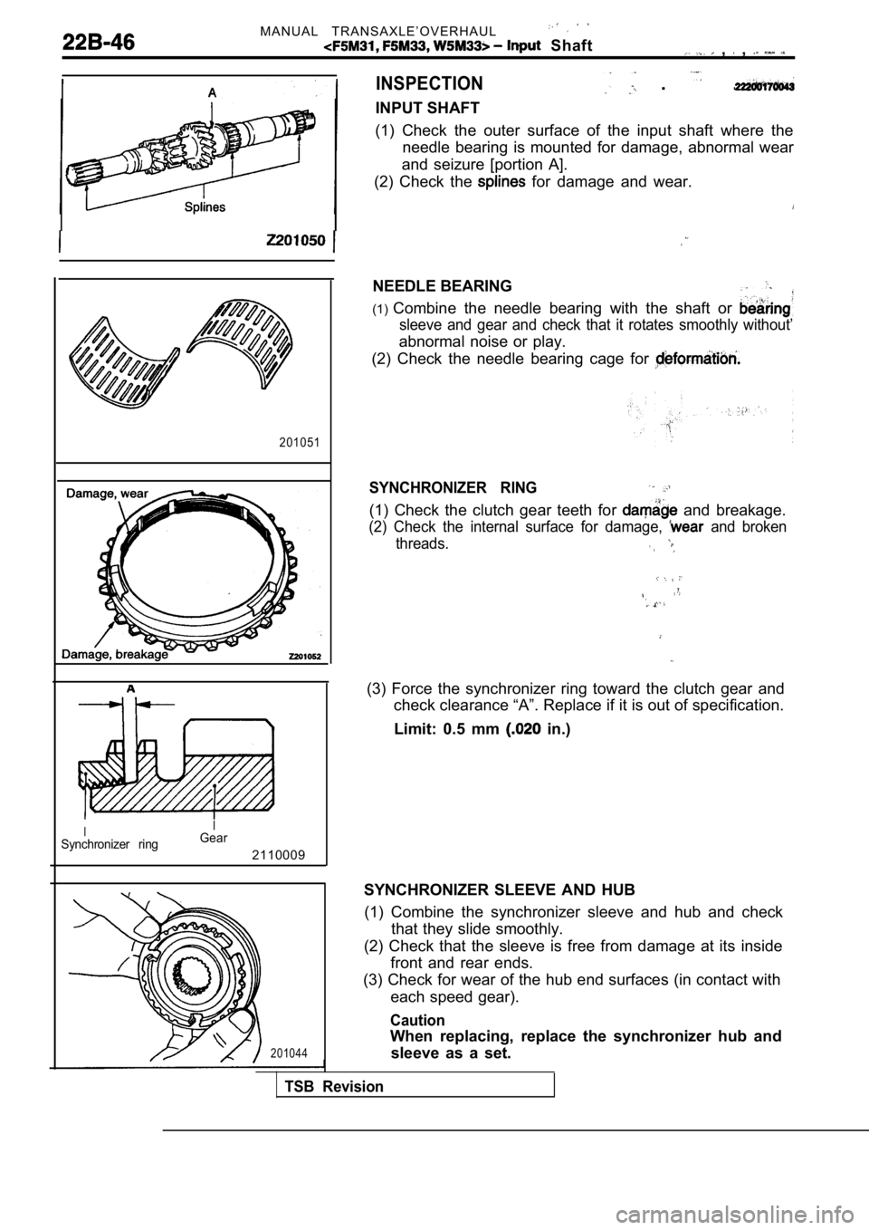
INSPECTION
INPUT SHAFT
. . .
(1) Check the outer surface of the input shaft wher
e the
needle bearing is mounted for damage, abnormal wear
and seizure [portion A].
(2) Check the
for damage and wear.
NEEDLE BEARING
(1) Combine the needle bearing with the shaft or
sleeve and gear and check that it rotates smoothly without’
abnormal noise or play.
(2) Check the needle bearing cage for
SYNCHRONIZER RING
(1) Check the clutch gear teeth for and breakage.
(2) Check the internal surface for damage, and broken
threads.
(3) Force the synchronizer ring toward the clutch g ear and
check clearance “A”. Replace if it is out of specif ication.
Limit: 0.5 mm
in.)
SYNCHRONIZER SLEEVE AND HUB (1) Combine the synchronizer sleeve and hub and che ck
that they slide smoothly.
(2) Check that the sleeve is free from damage at it s inside
front and rear ends.
(3) Check for wear of the hub end surfaces (in cont act with
each speed gear).
Caution
When replacing, replace the synchronizer hub and sleeve as a set.
TSB Revision
Page 943 of 2103
MANUAL TRANSAXLE OVERHAUL
Gear
ring
201051
Gear2110009
and wear
Scratches and damage
and wear
I N S P E C T I O N
INTERMEDIATE GEAR
(1) Check the outer surface of the
the needle bearing is mounted’ abnormal
wear and seizure
(2) Check the splines for and
NEEDLE BEARING
(1) Combine the bearing or bearing’
sleeve and gear and check it rotates Smoothly without
abnormal noise or play.
(2) Check the needle bearing for’
SYNCHRONIZER RING
(1) Check the clutch gear teeth for damage breakage.
(2) Check the internal surface for damage,, broken
threads.
(3) Force the ring toward
check clearance “A”. if it is of specification.
Limit: 0.5 mm
in.)
SYNCHRONIZER OUTER RING, INNER RING AND CONE (1) Check that there are no scratches of damage on the
clutch gear teeth and cone surface.
(2) Check that there are no scratches, wear or peel ing on
the paper lining