1990 MITSUBISHI SPYDER ESP
[x] Cancel search: ESPPage 8 of 2103
G E N E R A L How to Use Troubleshooting/Inspection Service Points
Troubleshooting of electronic control systems for which the scan tool the basic outline
described below. Furthermore, even in systems for w hich the scan tool cannot be used, part of these
systems still follow this outline.
TROUBLESHOOTING CONTENTS
1. STANDARD FLOW OF DIAGNOSTIC TROUBLESHOOTING
The main procedures for diagnostic troubleshooting are shown.
2. SYSTEM OPERATION AND SYMPTOM VERIFICATION TESTS If verification of the trouble symptoms is difficul t, procedures for checking operation and verifying
trouble symptoms are shown.
3. DIAGNOSTIC FUNCTION The following diagnostic functions are shown.
l ,Method of reading diagnostic trouble codes
Method of erasing diagnostic trouble codes
lInput inspection service points
4. INSPECTION CHART FOR DIAGNOSTIC TROUBLE CODES
5. INSPECTION PROCEDURE FOR DIAGNOSTIC TROUBLE CODE S
Indicates the inspection procedures corresponding t o each diagnostic trouble code. (Refer to the
next page on how to use the inspection procedures.)
6. INSPECTION CHART FOR TROUBLE SYMPTOMS
If there are trouble symptoms, even though the scan tool displays no diagnostic inspection
procedures for each trouble symptom will be found b y means of this chart.
7. INSPECTION PROCEDURE FOR TROUBLE SYMPTOMS
Indicates the inspection procedures corresponding t o each trouble symptoms the Inspection
Chart for Trouble Symptoms. (Refer to the next page on how to use the inspection procedures.)
8. DATA LIST REFERENCE TABLE
Inspection items and normal judgement values have b een provided in this chart as reference
9. CHECK AT ECU TERMINALS
Terminal numbers for the ECU connectors, inspection items and standard values have been provided
in this chart as reference information.
Terminal Voltage Checks
1. Connect a needle-nosed wire probe or paper clip to a voltmeter probe.
2.Insert the needle-nosed wire probe into each of the ECU connector from the wire side,
and measure the voltage while referring to the chec k chart.
NOTE
1. Measure voltage with the ECU connectors connecte d.
2. You may find it convenient to pull out the ECU t o make it easier to reach the connector
terminals.
3. Checks don’t have to be carried out in the order given in the chart.
Short-circuiting the positive probe between a connector damage
the vehicle wiring, the sensor, the ECU, or all thr ee.
Use care to prevent this
3. If voltage readings differ from Normal Condition values, related actuators, and
wiring, then replace or repair.
TSB Revision
Page 9 of 2103
GENERAL How to Use Troubleshooting/Inspection Service Points
4.After repair or replacement, recheck the voltmeter to confirm the repair
the problem.
Terminal Resistance and Continuity Checks
1. Turn the ignition switch to off.
2. Disconnect the ECU connector.
3.Measure the resistance and check for continuity bet ween the terminals of the ECU
connector while referring to the check chart.
NOTE
Checks don’t have to be carried out in the order gi ven in the chart.
Cautlon
If resistance and continuity checks are performed the wrong terminals, damage
vehicle wiring, sensors, ECU, and/or ohmmeter may o ccur.
Use care to prevent this!
4.If the ohmmeter shows any deviation from the Normal Condition value, check the corresponding
5.
sensor, actuator and related electrical wiring, then repair or replace.
After repair or replacement, recheck with the ohmme ter to confirm that the repair
the problem.
10. INSPECTION PROCEDURES USING AN OSCILLOSCOPE
When there are inspection procedures using an oscil loscope, these are listed here.
,
TSB Revision
Page 13 of 2103
G E N E R A L How to Use __
HOW TO COPE WITH INTERMITTENT
Most intermittent malfunctions occur under certain conditions. If those conditions can be identified, the
cause will be easier to find.
TO COPE WITH INTERMITTENT MALFUNCTION;1. Ask the customer about the malfunction
Ask what it feels
it sounds like, etc.
Then ask about
conditions; weather,
frequency of occurrence, and so on.
2.Determine the from the custom-
er’s responses
Typically, almost all intermittent malfunctions
occur from conditions like vibration, tempera-
ture and/or moisture change, poor connections.
From the customer’s replies, it should be rea-
soned which condition is influenced.
3. Use simulation test In the cases of vibration or poor connections,
use the simulation tests below to attempt to
duplicate the customer’s complaint. Determine
the most likely circuit(s) and perform
tion tests on the connectors and parts of that
circuit(s). Be sure to use the inspection proce-
dures provided for trouble codes
a n d t r o u b l e s y m p t o m s .
For temperature and/or moisture conditions re-
lated intermittent malfunctions, using common
sense, try to change the of
circuit components, then use
tion tests below,
4. Verify the intermittent malfunction is elimi-
nated
Repair the malfunctioning part and try to
the condition(s) again to verify the intermit-
tent malfunction has been eliminated.
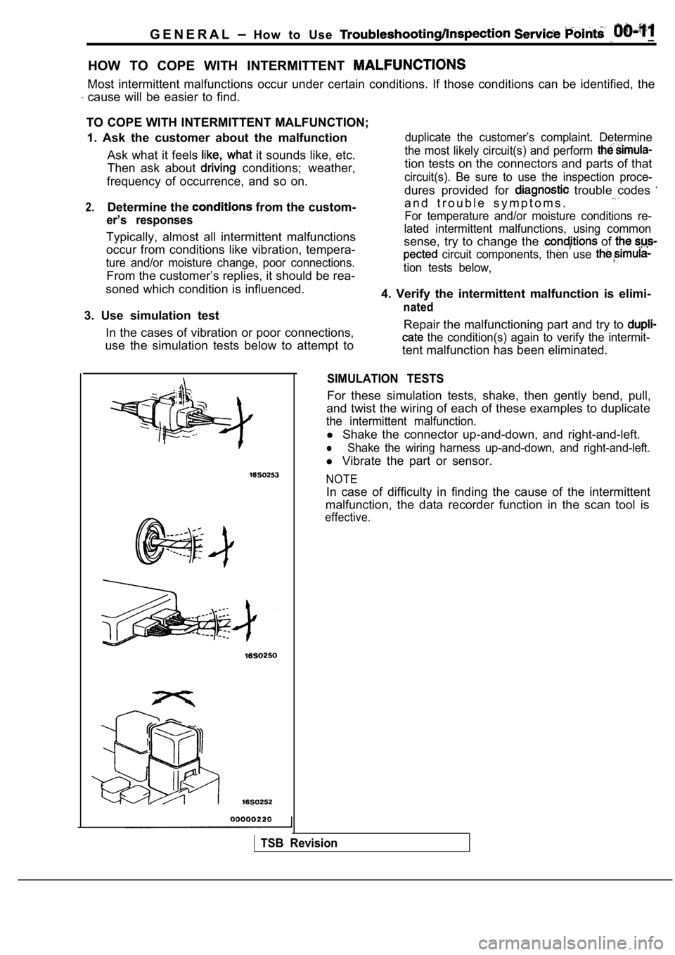
SIMULATION TESTS
For these simulation tests, shake, then gently bend , pull,
and twist the wiring of each of these examples to d uplicate
the intermittent malfunction.
l Shake the connector up-and-down, and right-and-left .
lShake the wiring harness up-and-down, and right-and -left.
l Vibrate the part or sensor.
NOTE
In case of difficulty in finding the cause of the i ntermittent
malfunction, the data recorder function in the scan tool is
effective.
TSB Revision
Page 35 of 2103
GENERAL Lubrication arid Maintenance,
00100120067
Maintenance and lubrication service recommenda-
tions have been compiled to provide maximum
protection for the vehicle owner’s investment
against all reasonable types of driving conditions.
Since these conditions vary with the individual ve-
hicle owner’s driving habits, the area in which the
vehicle is operated and the type of to which
the vehicle is subjected, it is necessary to prescr ibe
lubrication and maintenance service on a time fre-
quency as well as mileage interval basis.
Oils, lubricants and greases are classified and
graded according to standards recommended by
the Society of Automotive Engineers (SAE), the
American Petroleum Institute (API) and the National
Lubricating Grease Institute (NLGI).
MAINTENANCE SCHEDULES
Information for service maintenance is provided
under “SCHEDULED MAINTENANCE TABLE”.
Three schedules are provided; one for “Required
Maintenance”, one for “General Maintenance” and
one for “Severe Usage Service”. Item numbers in the “SCHEDULED MAINTE-
NANCE TABLE” correspond to the item
in the “MAINTENANCE SERVICE” section.
SEVERE SERVICE
Vehicles operating under severe service conditions
will require more frequent service. Component service information is included in ap-
propriate units for vehicles operating under one
or more of the following conditions:
1. Police, taxi, or commercial type operation
2. Operation of Vehicle
(1) Short-trip operation at freezing temperature
(engine not thoroughly warmed up)
(2) More than 50% operation in heavy city traf-
fic during hot weather above
(3) Extensive idling
(4) Driving in sandy areas
(5) Driving in salty areas
(6) Driving in dusty conditions
ENGINE OIL
Either of the following engine oils should be used:
(1) Engine oil displaying EOLCS certification mark
(2) Engine oil conforming to the API classification SH
or ECII.
For further details, refer to “LUBRICANTS SELEC-
TION” section.
Caution
Test to EPA have shown
laboratory animals develop skin after
prolonged contact with used engine oil. Accord-
ingly, the potential exists for
to
a number:, of skin disorders, including
from such exposure to used
Care should be taken, when changing
engine oil, to minimize the
of exposure time to used your
skin. Protective clothing and that
be penetrated by worn.
should be thoroughly with soap
use waterless hand remove,
any used engine oil. Do not use gasoline, thin- ners, or solvents.
GEAR LUBRICANTS
The SAE grade number indicates
of Multi-purpose Gear Lubricants.
The API classification system
cants in terms of gear lubricants
conforming to API
or ‘with a
of SAE are recommended for
transaxle.
LUBRICANTS GREASES
Semi-solid lubricants bear the
designation
and are further classified as grades 0, 1, 2; 3 etc .
Whenever “Chassis Lubricant” is specified, Multi-
purpose Grease,
grade 2, should be used.
FUEL USAGE
Your car must use unleaded
This car has a fuel filler tube especially
to accept only the smaller-diameter unleaded gaso- line dispensing nozzle.
Caution
Using leaded gasoline in your car will damage
the catalytic converter and oxygen sensor, and
affect the warranty coverage validity.
Your car is designed to operate on premium
leaded gasoline having a minimum octane rating
of 91 or 95 RON (Research Octane
If premium unleaded gasoline is not
leaded gasoline having a octane rating of 87,
91 RON (Research Octane Number) may be used. In this case, the performance and fuel consumption
will suffer a little degradation.
Gasolines Containing Alcohol
Some gasolines sold at service stations contain
alcohol, although they may not be so identified.
TSB Revision
Page 101 of 2103
ENGINE Timing
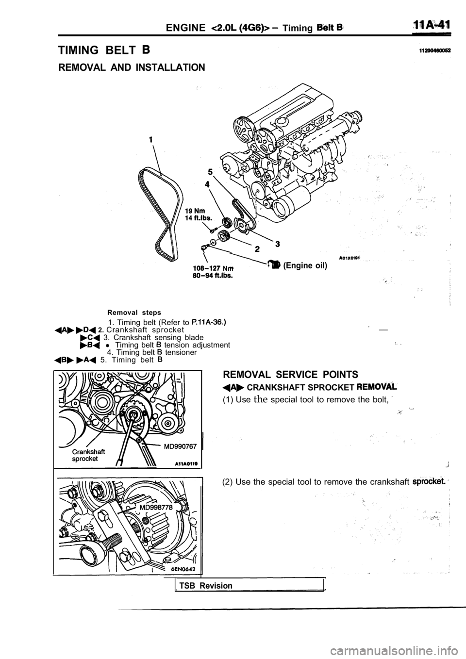
TIMING BELT
REMOVAL AND INSTALLATION
(Engine oil) Nm
Removal steps1. Timing belt (Refer to
2. Crankshaft sprocket 3. Crankshaft sensing blade l Timing belt tension adjustment
4. Timing belt tensioner 5. Timing belt
__
REMOVAL SERVICE POINTS
CRANKSHAFT SPROCKET
(1) Use thespecial tool to remove the bolt,
(2) Use the special tool to remove the crankshaft
TSB Revision
Page 122 of 2103
ENGINE OVERHAUL Timing’
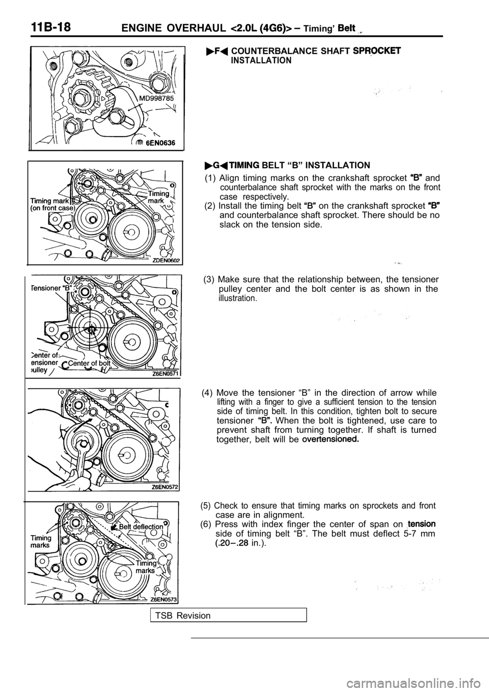
COUNTERBALANCE SHAFT
INSTALLATION
BELT “B” INSTALLATION
(1) Align timing marks on the crankshaft sprocket
and
counterbalance shaft sprocket with the marks on the front
case respectively.
(2) Install the timing belt on the crankshaft sprocket
and counterbalance shaft sprocket. There should be no
slack on the tension side.
(3) Make sure that the relationship between, the te nsioner
pulley center and the bolt center is as shown in th e
illustration.
(4) Move the tensioner “B” in the direction of arrow while
lifting with a finger to give a sufficient tension to the tension
side of timing belt. In this condition, tighten bolt to secure
tensioner When the bolt is tightened, use care to
prevent shaft from turning together. If shaft is tu rned
together, belt will be
(5) Check to ensure that timing marks on sprockets and front
case are in alignment.
(6) Press with index finger the center of span on
side of timing belt “B”. The belt must deflect 5-7 mm
in.).
TSB Revision
Page 161 of 2103
ENGINE OVERHAUL
11300850104
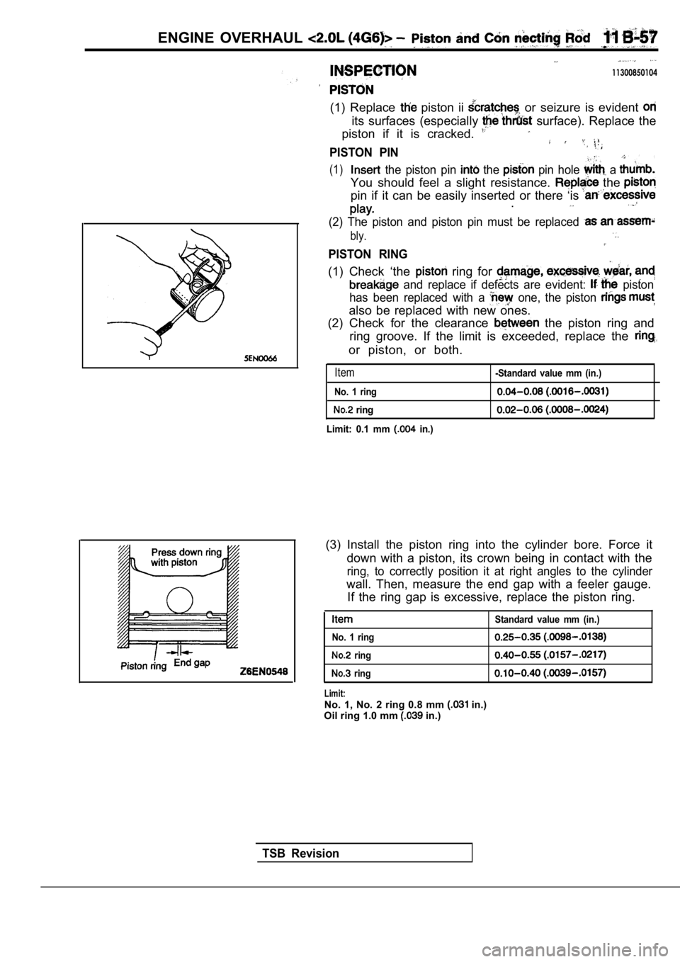
(1) Replace piston ii or seizure is evident
its surfaces (especially surface). Replace the
piston if it is cracked.
PISTON PIN
(1) the piston pin the pin hole a
You should feel a slight resistance. the
pin if it can be easily inserted or there ‘is .
(2) The piston and piston pin must be replaced
bly.
PISTON RING
(1) Check ‘the ring for
and replace if defects are evident: piston
has been replaced with a
one, the piston
also be replaced with new ones.
(2) Check for the clearance
the piston ring and
ring groove. If the limit is exceeded, replace the
or piston, or both.
Item
No. 1 ring
ring
Limit: 0.1 mm
in.)
-Standard value mm (in.)
(3) Install the piston ring into the cylinder bore. Force it
down with a piston, its crown being in contact with the
ring, to correctly position it at right angles to the cylinder
wall. Then, measure the end gap with a feeler gauge .
If the ring gap is excessive, replace the piston ri ng.
Standard value mm (in.)
No. 1 ring
ring
ring
Limit:No. 1, No. 2 ring 0.8 mm in.)
Oil ring 1.0 mm in.)
TSB Revision
Page 221 of 2103
ENGINE OVERHAUL Ignition
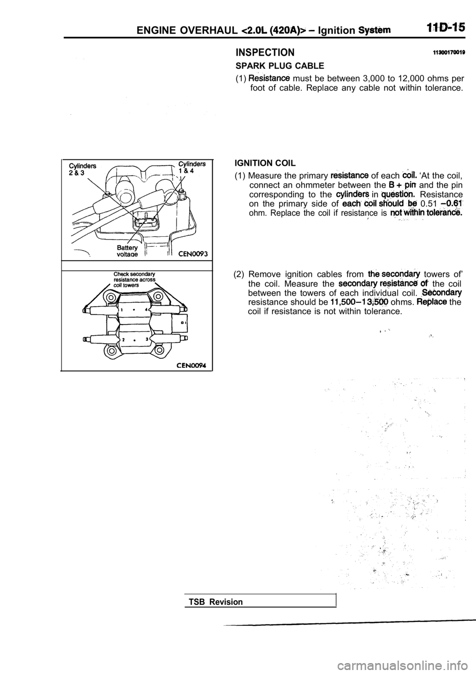
INSPECTION
SPARK PLUG CABLE
(1)
must be between 3,000 to 12,000 ohms per
foot of cable. Replace any cable not within toleran ce.
IGNITION COIL
(1) Measure the primary
of each ‘At the coil,
connect an ohmmeter between the
and the pin
corresponding to the
in Resistance
on the primary side of
0.51
ohm. Replace the coil if resistance is
(2) Remove ignition cables from towers of’
the coil. Measure the
the coil
between the towers of each individual coil.
resistance should be ohms. the
coil if resistance is not within tolerance.
,
TSB Revision