1990 MITSUBISHI SPYDER ESP
[x] Cancel search: ESPPage 290 of 2103
11ENGINE and Camshaft Oil ‘Seat
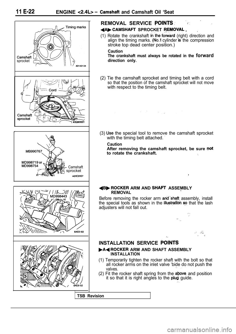
REMOVAL SERVICE
sprocket
Camshaft sprocket
SPROCKET ,
(1) Rotate the crankshaft (right) direction and
align the timing marks.
cylinder the compression
stroke top dead center position.)
Caution
The crankshaft must always be rotated in the forward
direction only.
(2) Tie the camshaft sprocket and timing belt with a cord
so that the position of the camshaft sprocket will not move
with respect to the timing belt.
(3)
the special tool to remove the camshaft sprocket
with the timing belt attached.
Caution
After removing the camshaft sprocket, be sure
to rotate the crankshaft.
,
ARM AND ASSEMBLY
REMOVAL.
Before removing the rocker arm assembly, install
the special tools as shown in the
that the lash
adjusters will not fall out.
,
INSTALLATION SERVICE
ARM AND SHAFT ASSEMBLY
INSTALLATION
(1) Temporarily tighten the rocker shaft with the b olt so that
all rocker arms on the inlet valve ‘bide do not push the
valves.
(2) Fit the rocker shaft spring from the and position
it so that it is right angles to the
guide.
TSB Revision
Page 299 of 2103
ENGINE Cylinder Head
sprocketCamshaft
sprocket
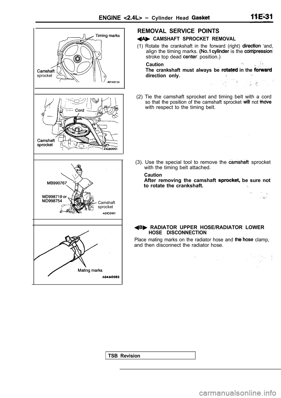
REMOVAL SERVICE POINTS
CAMSHAFT SPROCKET REMOVAL
(1) Rotate the crankshaft in the forward (right) ‘and,
align the timing marks. is the
stroke top dead position.)
Caution .
The crankshaft must always be in the
direction only.
(2) Tie the camshaft sprocket and timing belt with a cord
so that the position of the camshaft sprocket not
with respect to the timing belt.
(3). Use the special tool to remove the
sprocket
with the timing belt attached.
Caution
After removing the camshaft be sure not
to rotate the crankshaft.
RADIATOR UPPER HOSE/RADIATOR LOWER
HOSE DISCONNECTION
Place mating marks on the radiator hose and clamp,
and then disconnect the radiator hose.
TSB Revision
Page 326 of 2103
ENGINE OVERHAUL Timing,
ENGINE SUPPORT BRACKET INSTALLATION
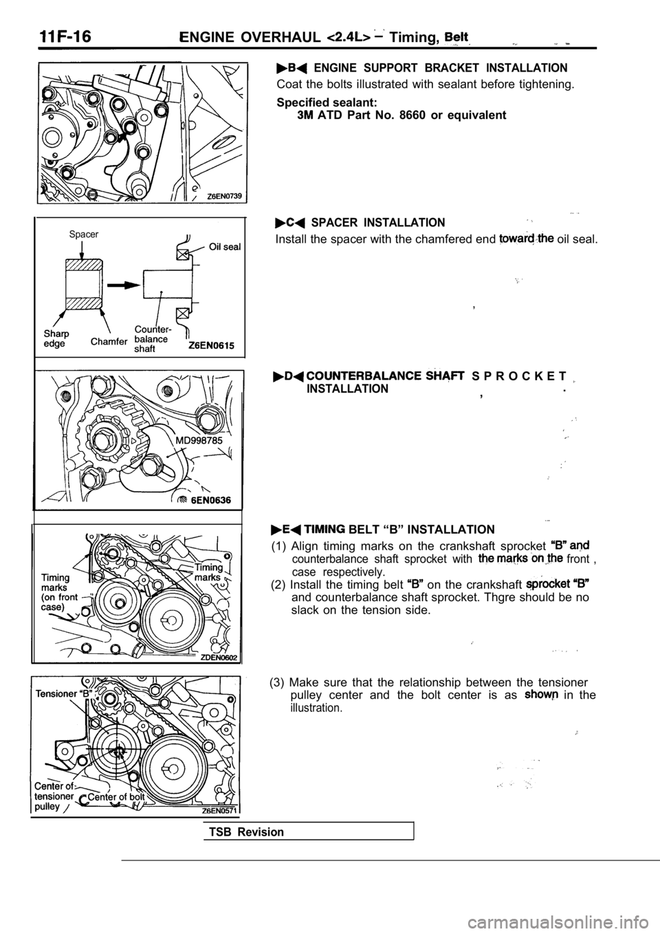
Spacer
Coat the bolts illustrated with sealant before tightening.
Specified sealant:
ATD Part No. 8660 or equivalent
SPACER INSTALLATION
Install the spacer with the chamfered end oil seal.
,
S P R O C K E T
INSTALLATION.
,
BELT “B” INSTALLATION
(1) Align timing marks on the crankshaft sprocket
counterbalance shaft sprocket with front ,
case respectively.
(2) Install the timing belt on the crankshaft
and counterbalance shaft sprocket. Thgre should be no
slack on the tension side.
(3) Make sure that the relationship between the ten sioner
pulley center and the bolt center is as
in the
illustration.
TSB Revision
Page 374 of 2103
ENGINE LUBRICATION General Information/Lubricants
G E N E R A L I N F O R M A T I O N
The lubrication method is a fully force-fed, full-f low
filtration type.
ENGINE OILS
Health Warning
Prolonged and repeated contact with mineral oil
will result in the removal of natural fats from the
skin, leading to dryness, irritation and dermatitis .
In addition, used engine oil
potentially
Recommended Precautions
The most effective precaution is to adapt working
practices which prevent, as far as practicable, the
risk of skin contact with mineral oils, for example
by using enclosed systems for handling used engine
oil and by degreasing components, where
practicable, before handling them.
Other precautions:
lAvoid prolonged and repeated contact with oils,
particularly used engine oils.
l Wear protective clothing, including impervious
gloves where practicable.
l Avoid contaminating clothes, particularly
underpants, with oil.
l Do not put oily rags in packets, the use of
overalls without pockets will avoid this.
l Do not wear heavily soiled clothing and
oil-impregnated foot-wear. Overalls must be
cleaned regularly and kept separate from
personal clothing.
LUBRICANTS
harmful contaminants which may cause skin cancer.
Adequate means of skin protection and washing
facilities must
provided.
Where there is a risk of eye contact, eye protection should be worn, for example,
chemical goggles or face shields; in addition
an eye wash facility should be provided.
Obtain First Aid treatment immediately for open
cuts and wounds.
Wash regularly with soap and water to ensure
all oil is removed, especially before
cleansers and nail brushes will help). After
cleaning, the application of
containing lanolin to replace the natural
oil is advised.. .
Do not use gasoline, kerosine, diesel fuel,
oil, thinners or solvents for cleaning skin.
Use barrier creams, applying them before each
work period, to help the removal of oil from
the skin after work.
If skin disorders develop, obtain medical advice
without delay.
Items Engine oil (API classification) Quantity (qts.)
Oil filter Engine (Non-turbo)
Engine (Turbo) and
Engine
Oil cooler
Engine (Turbo)>
Total quantity
Engine (Non-turbo)
and
Engine SH or higher
0.5
0.3
0.1
4.3 (4.5)
IIIII
Engine (Turbo) 4.4 (4.6)I
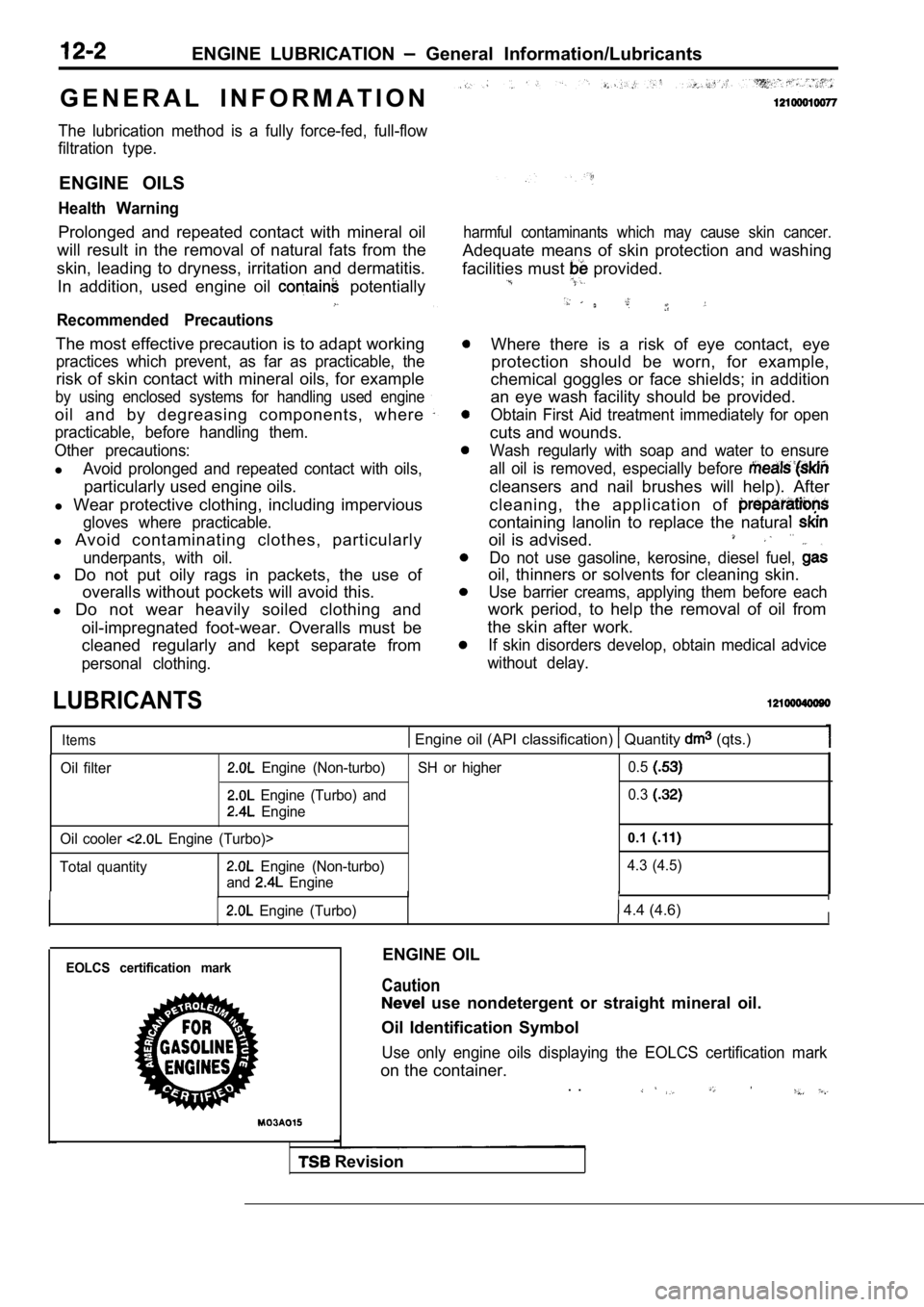
EOLCS certification markENGINE OIL
Caution
use nondetergent or straight mineral oil.
Oil Identification Symbol
Use only engine oils displaying the EOLCS certifica tion mark
on the container.
. .
Revision
Page 383 of 2103
ENGINE (NON-TURBO)> General
FUEL INJECTION
ENGINE (NON-TURBO)>
GENERAL INFORMATION
The Fuel Injection System consists
of sensors which detect the engine conditions,
the POWERTRAIN CONTROL MODULE(PCM) which controls the system based on
signals from these sensors, and actuators
which operate under the control of the PCM.
FUEL INJECTION CONTROL
The injector drive times and injector timing are
controlled so that the optimum air/fuel mixture
is supplied to the engine to correspond to the
continually-changing engine operation condi-
tions.
A single injector is mounted at the intake port
of each cylinder. Fuel is sent under pressure
from the fuel tank by the fuel pump, with the
pressure regulated by the fuel pressureregulator. The regulated fuel is distributed
to each of the injectors. Fuel injection is normally carried out once for
each cylinder for every two rotations of the
crankshaft. The firing order is
This
IDLE AIR CONTROL The idle speed’ is kept at the optimum speed
by controlling the amount of air that bypasses
the throttle valve in accordance with changes in idling conditions and engine load during
idling.
The PCM drives the idle air control (IAC) motor
to keep the engine running at the idle
target speed in accordance with the engine
IGNITION TIMING CONTROL
The ignition power transistor is built into the
PCM. It turns the ignition primary circuit on
and off to respectively supply and cut off primary
current flow to the ignition coil. The PCM carries
activities such fuel
injection control, idle air control and ignition
timing control.
In addition, the
diagnostict e s twhich simplify
troubleshooting when a problem develops.
is called The PCM
air/fuel mixture by carrying out “open-loop”
control when the engine is cold or operating
under high load conditions in to maintain
engine performance.
In addition, when the engine warm or
operating under normal
the PCM
controls the air/fuel mixture by using the heated
oxygen sensor signal to carry out “closed-loop”
control in order to obtain the theoretical air/fuel
mixture ratio that provides the maximum
cleaning
from the three way
catalyst.
coolant temperature and air conditioning load.
In addition, when the air conditioning switch
is turned off and on while the engine is idling,
the
motor operates to adjust the throttle
valve bypass air amount in accordance with
the engine load conditions in order to avoid
fluctuations in the engine speed.
This controls the ignition timing in order to
provide the optimum ignition timing with respect
to the engine operating conditions. The ignition
timing is determined by the PCM from the
engine speed, intake air volume, engine coolant
temperature and atmospheric pressure.
TSB Revision
Page 384 of 2103
ENGINE (NON-TURBO)>
DIAGNOSTIC TEST MODE
l When an abnormality is detected in one
of the sensors or actuators related to
emission control, the CHECK
MALFUNCTION INDICATOR LAMP
nates as a warning to the driver.
l When an abnormality is detected in one
of the sensors or actuators, a diagnostic
OTHER CONTROL FUNCTIONS
t r o u b l e c o d e
a b n o r m a l i t y i s o u t p u t .
lThe RAM data inside the PCM that is
to the sensors and
by means of the scan tool.
In addition, the actuators can be controlled
under certain circumstances. . ,
1. Fuel Pump Control
Turns the fuel pump relay ON so that current
is supplied to the fuel pump while the engine
is cranking or running.
2. A/C Compressor Clutch Relay Control Turns the A/C compressor clutch ON and
OFF.
3. Fan Relay Control
The radiator fan and condenser fan speeds
are controlled in response to the engine
coolant temperature and vehicle speed. 4. Generator
Controls the generator in order
to control the generated current.
5. Engine Speedometer or Tachometer
Control.
Sends a pulse signal which ‘corresponds
to the engine speed to the’ speedometer
unit..
6. Evaporative Emission Purge
C o n t r o l
Refer to GROUP 17.
7. Electric EGR Transducer Solenoid Control Refer to GROUP 17.
Throttle body
Sensors
Actuators
Specifications
Throttle bore mm (in) 52 (2.05)
Throttle position sensor Variable resistor type
Idle air control motor
Stepper motor type [Stepper type
bypass air control system]’,
Manifold absolute pressure sensor Semiconductor type
Intake air temperature sensorT h e r m i s t o r t y p e
Engine coolant temperature sensorThermistor type .
Heated oxygen sensorZircon type .
Vehicle speed sensorElectromagnetic resistance element type
TCM output signal
Camshaft position sensor Hall element type’
Crankshaft position sensor
Hall element type
Knock sensor Piezoelectric type
Power steering pressure switch Contact switch type
fuel injection (MFI) relay (ASD relay)
Contact switch type
Fuel pump relay Contact switch type
Injector type and number Electromagnetic type, 4
Electric EGR transducer solenoid ON/OFF type solenoid valve
Evaporative emission purge solenoid Duty cycle type solenoid valve
TSB Revision
Page 389 of 2103
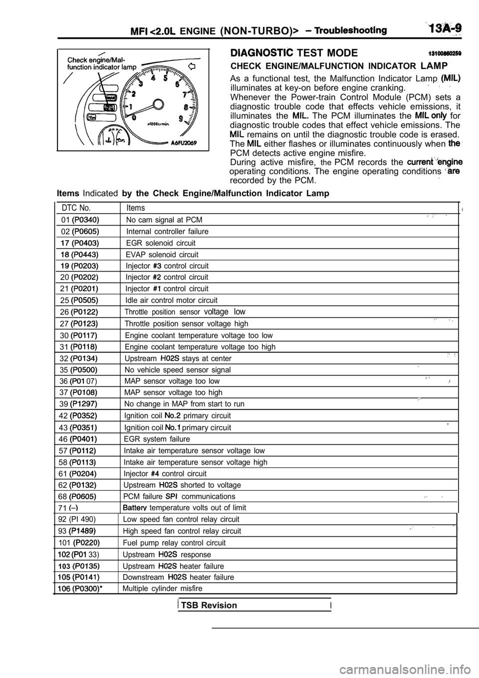
ENGINE (NON-TURBO)>
TEST MODE
CHECK ENGINE/MALFUNCTION INDICATOR LAMP
As a functional test, the Malfunction Indicator Lam p
illuminates at key-on before engine cranking.
Whenever the Power-train Control Module (PCM) sets a
diagnostic trouble code that effects vehicle emissi ons, it
illuminates the
The PCM illuminates the for
diagnostic trouble codes that effect vehicle emissi ons. The
remains on until the diagnostic trouble code is erased.
The
either flashes or illuminates continuously when
PCM detects active engine misfire.
During active misfire, thePCM records the
operating conditions. The engine operating conditio ns
recorded by the PCM.
ItemsIndicated by the Check Engine/Malfunction Indicator Lamp
DTC No. Items
01No cam signal at PCM
02Internal controller failure
EGR solenoid circuit
EVAP solenoid circuit
Injector control circuit
20Injector control circuit
21Injector control circuit
25Idle air control motor circuit
26Throttle position sensor voltage low
27Throttle position sensor voltage high
30Engine coolant temperature voltage too low
31Engine coolant temperature voltage too high
32Upstream stays at center
35
No vehicle speed sensor signal
36
07) MAP sensor voltage too low
37MAP sensor voltage too high
39No change in MAP from start to run
42Ignition coil primary circuit
43Ignition coil primary circuit
46
EGR system failure
57Intake air temperature sensor voltage low
58Intake air temperature sensor voltage high
61Injector control circuit
62Upstream shorted to voltage
68PCM failure communications
71 temperature volts out of limit
, .
,
92 (PI 490)
93
101
33)
103
Low speed fan control relay circuit
High speed fan control relay circuit
Fuel pump relay control circuit
Upstream
response
Upstream
heater failure
Downstream
heater failure
Multiple cylinder misfire
TSB RevisionI
Page 394 of 2103
ENGINE (NON-TURBO)>
LEAK DETECTION PUMP MONITOR
Related diagnosis trouble codes (DTC)
l EVAP leak monitor small leak detected
l
EVAP leak monitor large leak detected
l
EVAP leak monitor pinched hose found
Operation
The leak detection assembly incorporates two primar y functions: it must detect a the
system and seal the evaporative system so the leak detection test can be run.. .
The’ primary components within the assembly are: A three port solenoid activates ‘both of the
functions listed above; a pump which contains a swi tch; two check valves and a spring/diaphragm, a’
canister vent valve (CVV) seal which contains a spr ing loaded vent seal valve.
Immediately after a cold start, between predetermin ed temperature thresholds limits, the three port
solenoid is briefly energized. This initializes the pump by drawing air into the pump cavity and also closes
the vent seal. During non test conditions the vent seal is held open by the pump diaphragm assembly
which pushes it open at the full travel position. The vent seal will remain closed while the pump is c ycling
due to the reed switch triggering of the three port solenoid that prevents the diaphragm assembly from
reaching full travel. After the brief initializatio n period, the solenoid is de-energized allowing atm ospheric
pressure to enter the pump cavity, thus permitting the spring to drive the diaphragm which forces air
out of the pump cavity and into the vent system. Wh en the solenoid is energized and de-energized,
the cycle is repeated creating flow in typical diaphragm pump fashion. The pump is controlled in 2 mod es:
Pump Mode: The pump is cycled at a fixed rate to achieve a rapid pressure build in order to shorten
the overall test length.
Test Mode: The solenoid is energized with a fixed d uration pulse. Subsequent fixed pulses occur
when the diaphragm reaches the Switch closure point .
The spring in the pump is set so that the system wi ll achieve an equalized pressure of about 7.5”
The cycle rate of pump strokes is quite rapid as the system begins to pump up to this pressure.
As the pressure
the cycle rate starts to drop off. If there is no leak in the system, the pump
would eventually stop pumping at the equalized pres sure. If there is a leak, it will continue to pump
at a rate representative of the flow characteristic of the size of the leak. From this information we can
determine if the leak is larger than the required d etection limit (currently set at
orifice by CARB).
If a leak is revealed during the leak test portion of the test, the test is terminated at the end of the
mode and no further system checks will be performed .
After passing the leak detection phase of the test, system pressure is maintained by turning on the
solenoid until the purge system is activated. Purg e activation in effect creates a leak. The cycle
rate is again interrogated and when it increases du e to the flow through the purge system, the leak
check portion of the diagnostic is complete.
The canister vent valve will unseal the system afte r completion of the test sequence as the pump
diaphragm assembly moves to the full travel positio n.
Evaporative system functionality will be verified b y using the stricter evap purge flow monitor. At an
appropriate warm idle the LDP will be energized to seal the canister vent. The purge flow will be clocked
up from some small value in an attempt to see a shi ft in the 02 control system. If fuel vapor, indicated
by a shift in the 02 control, is present the test i s passed. If not, it is assumed that the purge syst em
is not functioning in some respect. The LDP is agai n turned off and the test is ended.
TSB Revision