Page 640 of 2103
ENGINE (TURBO)
AND ENGINE>
Analyzer
IGNITION COIL AND IGNITION
l Ignition coil primary
Refer to GROUP 16 Ignition System.
l Ignition power transistor control signal.
Measurement method
1. Disconnect the ignition power transistor connect or,
connect the special tool (test harness:.
tween. (All terminals should be connected.)
2.Connect the analyzer special patterns pickup to
tion power transistor connector terminal 2 No.
3) and terminal 7 (No. 1
No. 4)
A l t e r n a t e m e t h o d ( T e s t
1. Connect the analyzer special pickup to ECM
terminal
and connection terminal 23 respectively.
Standard Wave
Observation conditions
Special patterns
Pattern height
Pattern selector
Engine
D i s p l a y
Approx. 1,200
Standard wave pattern
TSB Revision
wave pattern
6 6: Spark advanceangleWave build-up section
Ignition power
transistor con-
trol signal wave
OFF ON
Dwell section Time
Page 741 of 2103

CONTENTS
AUTO-CRUISE CONTROL SYSTEM
. . . . . . . . . . . . . . . . . . . . . . . . . . . . . . . . . . . . .7
AUTO-CRUISE CONTROL* . . . . . . . . . . . . . . 40
GENERAL INFORMATION . . . . . . . . . . . . . . . . 7
ON-VEHICLE SERVICE. . . . . . . . . . . . . . . . . 33
Auto-cruise Control Cable Check and
Adjustment . . . . . . . . . . . . . . . . . . . . . . . . . . . . . .
33
Auto-cruise Control Component Check . . . . . 37
Auto-cruise Control System Operation Check
. . . . . . . . . . . . . . . . . . . . . . . . . . . . . . . . . . . . . . . . .
35
SERVICE SPECIFICATIONS . . . . . . . . . . . . . 8
SPECIAL TOOLS . . . . . . . . . . . . . . . . . . . . . . . . 8
TROUBLESHOOTING
ENGINE (NON-TURBO)> . . . . . . . . . . . 9
TROUBLESHOOTING
(TURBO) AND ENGINE> . . . . .
EMISSION CONTROL’ SYSTEM
. . . . .
CATALYTIC . . . . . . . . . . . . . .
General Information . . . . . . . . . . . . . . . . . . 57
EVAPORATIVE EMISSION .
SYSTEM. . . . . . . . . . . . . . . .
Air Conditioning . . . . . . . . . . . . . . . . . . . 52
Component Location
. . . . . . . . . . . . . . . . . .
Engine Coolant Temperature Sensor
Intake Air Temperature Sensor . . . . . . . . . . . . 52
WARNINGS REGARDING SERVICING OF SUPPLEMENTAL RESTRA INT SYSTEM (SRS) EQUIPPED
WARNING!
(1) Improper serviceor maintenance of any component of the or any SRS-related can to injuryorcleathtoservicepersonnel (from inadvertentfiring the SRS inoperative).
(2) Service or maintenance of any SRS component or SRS-related component must be performed only
MITSUBISHI dealer.
(3) MITSUBISHI dealer personnel must thoroughly rev iew this manual, and especially its GROUP
Restraint System (SRS) and GROUP 00 Maintenance Service, before any service or maintenance of any
componentof the SRS or any SRS-related component.
NOTEJhe includes the following components: warning light, air bag module, clock components (that may have to be removed/installed in connection with or areIndicated in the table of contents by an asterisk
Page 750 of 2103

ENGINE AND EMISSION CONTROL Auto-cruise
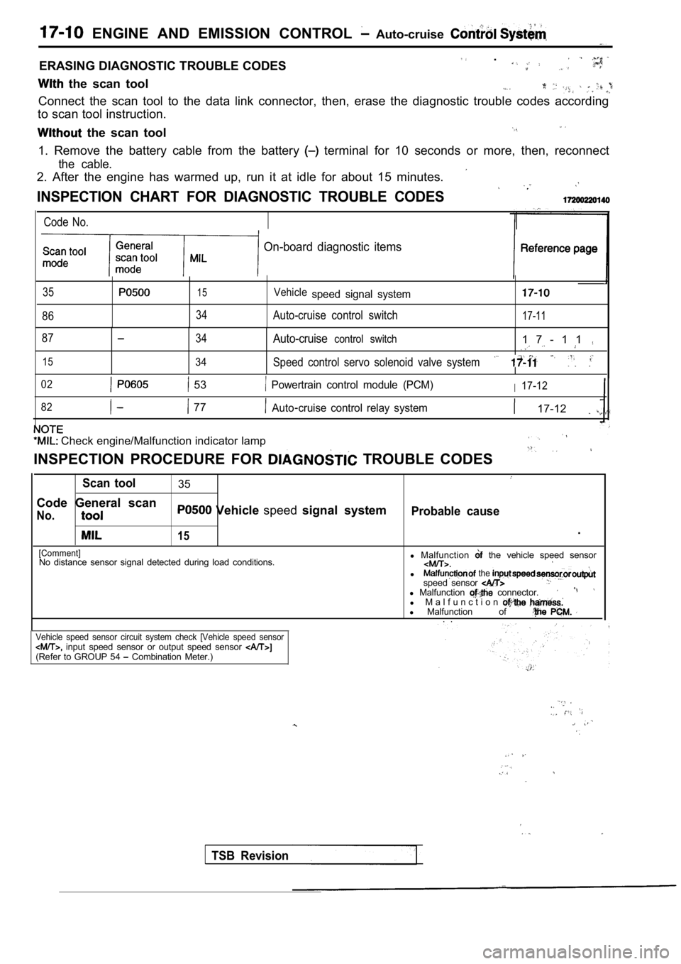
ERASING DIAGNOSTIC TROUBLE CODES .
the scan tool
Connect the scan tool to the data link connector, then, erase the diagnostic trouble codes according
to scan tool instruction.
the scan tool
1. Remove the battery cable from the battery terminal for 10 seconds or more, then, reconnect
the cable.
2. After the engine has warmed up, run it at idle f or about 15 minutes.
INSPECTION CHART FOR DIAGNOSTIC TROUBLE CODES
Code No.
On-board diagnostic items
35
86
15
34
Vehiclespeed signal system
Auto-cruise control switch17-11
87
15
34
34
Auto-cruisecontrol switch1 7 - 1 1
Speed control servo solenoid valve system
02 53 Powertrain control module (PCM)I17-12
82
77Auto cruise control relay system 17-12
Check engine/Malfunction indicator lamp
INSPECTION PROCEDURE FOR TROUBLE CODES
Scan tool35
Code General scan
No. Vehicle speedsignal systemProbable cause
15.
[Comment]No distance sensor signal detected during load cond itions.l
Malfunction the vehicle speed sensor
l the speed sensor l Malfunction connector.l M a l f u n c t i o nl Malfunction of . .
Vehicle speed sensor circuit system check [Vehicle speed sensor input speed sensor or output speed sensor (Refer to GROUP 54 Combination Meter.)
TSB Revision
Page 758 of 2103

ENGINE AND EMISSION CONTROL Auto-cruise Control
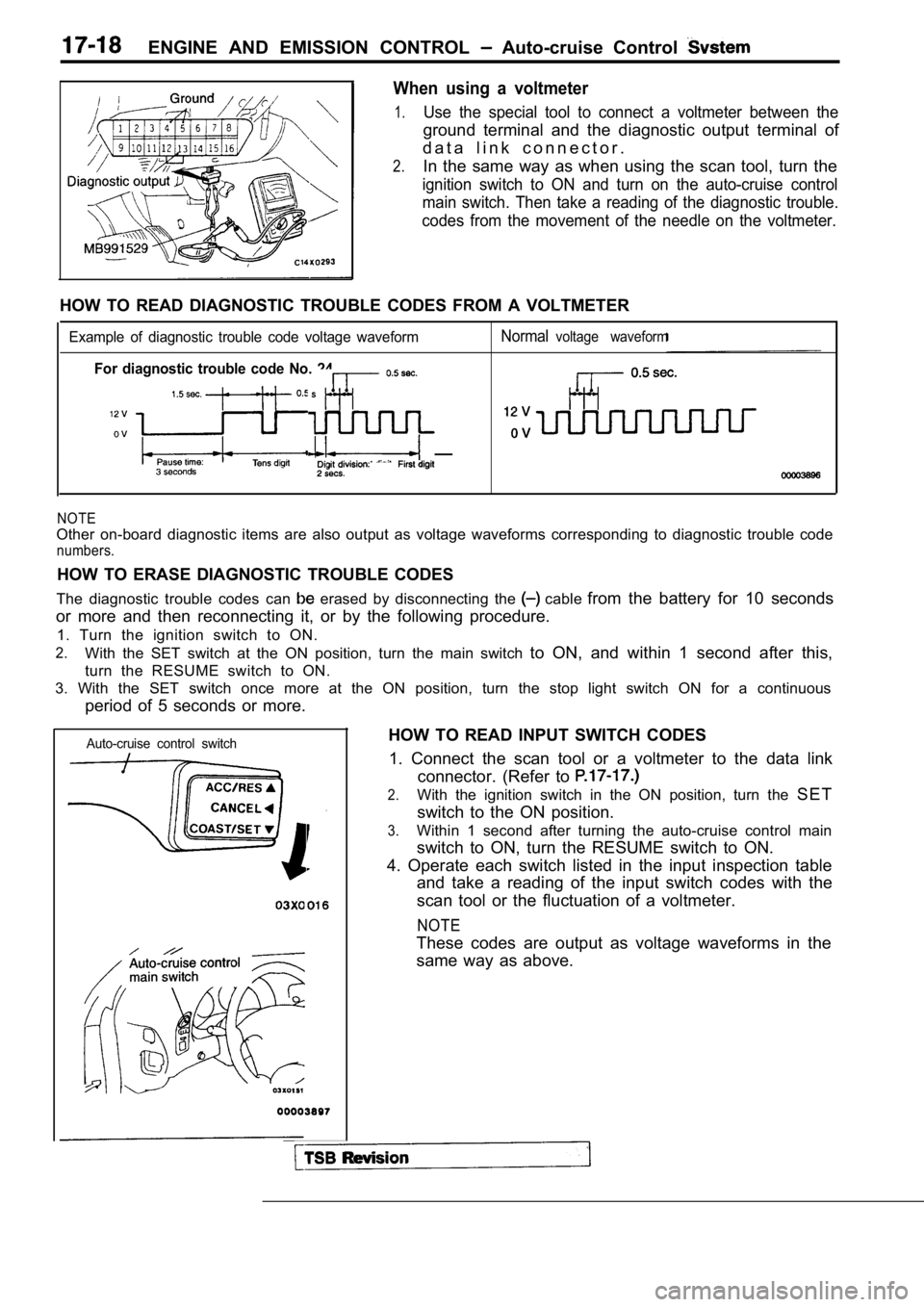
When using a voltmeter
1.Use the special tool to connect a voltmeter between the
ground terminal and the diagnostic output terminal of
d a t a l i n k c o n n e c t o r .
2.In the same way as when using the scan tool, turn t he
ignition switch to ON and turn on the auto-cruise c ontrol
main switch. Then take a reading of the diagnostic trouble.
codes from the movement of the needle on the voltme ter.
HOW TO READ DIAGNOSTIC TROUBLE CODES FROM A VOLTMET ER
Example of diagnostic trouble code voltage waveformNormalvoltage waveform
For diagnostic trouble code No. 24
NOTE
Other on-board diagnostic items are also output as voltage waveforms corresponding to diagnostic troub le code
numbers.
HOW TO ERASE DIAGNOSTIC TROUBLE CODES
The diagnostic trouble codes can
erased by disconnecting the cable from the battery for 10 seconds
or more and then reconnecting it, or by the followi ng procedure.
1. Turn the ignition switch to ON.
2.With the SET switch at the ON position, turn the ma in switch to ON, and within 1 second after this,
turn the RESUME switch to ON.
3. With the SET switch once more at the ON position , turn the stop light switch ON for a continuous
period of 5 seconds or more.
Auto-cruise control switch
TSB Revision
HOW TO READ INPUT SWITCH CODES
1. Connect the scan tool or a voltmeter to the data link
connector. (Refer to
2.With the ignition switch in the ON position, turn t he S E T
switch to the ON position.
3.Within 1 second after turning the auto-cruise contr ol main
switch to ON, turn the RESUME switch to ON.
4. Operate each switch listed in the input inspecti on table
and take a reading of the input switch codes with t he
scan tool or the fluctuation of a voltmeter.
NOTE
These codes are output as voltage waveforms in the
same way as above.
Page 783 of 2103
ENGINE AND EMISSION CONTROL Control
INSPECTION. .
AUTO-CRUISE CONTROL MAIN SWITCH CHECK
SwitchTerminal No.
ON0
0 0
AUTO-CRUISE CONTROL SWITCH CHECK
17200120082
Measure the resistance between the terminals when e ach
of the SET, RESUME and CANCEL switches is pressed.
If the values measured at this time correspond to t hose in
the table below, then there is no problem.
Switch position Resistance between terminals
Switch OFFNo continuity
CANCEL switch ONApprox. 0
RESUME switch ONApprox. 820
SETswitch ONApprox. 2,700
TSB Revision
Page 814 of 2103
Engine (Turbo) Engine>
Vacuum
Enginespeed
TSB Revision
Vacuum
Engine speed
PURGE VACUUM CHECK
(Turbo)>
1. Disconnect the vacuum hose from the throttle body purge
vacuum nipple and connect a hand vacuum pump to
t h e n i p p l e .
2. Vacuum is kept constant despite the increased en gine
speed.
NOTE
If no vacuum is generated, the throttle body purge port
may be clogged.
Engine (Turbo)>
1. Disconnect the vacuum hose from the intake manif old
purge vacuum nipple and connect a hand vacuum pump
to the nipple.
2. Vacuum is kept constant despite the increased en gine
speed.
NOTE
If no vacuum is generated, the intake manifold purge
port may be clogged.
Page 825 of 2103
and
Engine
Engine>
Vacuum
Enginespeed
EGR PORT VACUUM CHECK
1.Disconnect the vacuum hose (white stripe Engine
(Turbo)>, green stripe Engine>) from the throttle
body EGR vacuum nipple. Connect a hand vacuum pump
to the nipple.
2.Start the engine and gradually raise the speed.’ The vacu-
um reading on the pump should remain
NOTE
If no vacuum is generated, the throttle body purge port
m a y b e c l o g g e d .
Revision
Page 847 of 2103
CLUTCH OVERHAUL Specifications
LUBRICANTS
Engine (Turbo) and Engine>
ISpecified lubricants
Clutch release cylinder inner surface
Piston and cup of surface
Release fork fulcrum Brake Fluid or
Mitsubishi genuine grease
No. 0101011 or equivalent
Clutch release fork to release cylinder contact sur face
Clutch release bearing inside
Clutch disc spline
Clutch release bearing to release fork contact surf ace
Engine (Non-turbo)>
Items
Clutch flywheel assembly splineSpecified lubricantsMitsubishi genuine grease Part
No. or equivalent
Clutch release release cylinder contact surface
Clutch release lever to release bearing contact su rface
As required
As required
TSB Revision