1990 MITSUBISHI SPYDER ESP
[x] Cancel search: ESPPage 1149 of 2103
AUTOMATIC TRANSAXLE
ENGINE (NON-TURBO)> Troubleshooting
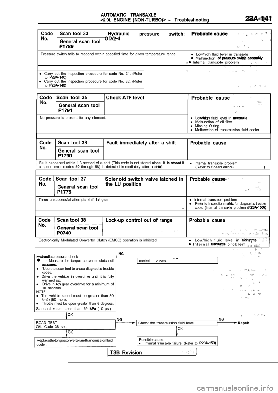
Code Scan tool 33Hydraulicpressureswitch:
No.General scan tool
Pressure switch falls to respond within specified t ime for given temperature range.
l Low/high fluid level in transaxle Malfunction Internal transaxle problem
,l Carry out the inspection procedure for code No. 31. (Refertol Carry out the inspection procedure for code No. 32. (Refer
to
Code Scan tool 35 Check level . Probable cause No.General scan tool
No pressure is present for any element.l fluid level in l
Malfunction of oil filter
l Missing O-ring
l Malfunction of transmission fluid cooler
Code Scan tool 38
Fault immediately after a shift Probable cause
No.General scan tool
Fault happened within 1.3 second of a shift (This code is not stored alone. It if
a speed error (codes through 58) is detected immediately after a l Internal transaxle problem
(Refer to Speed errors) I
Code
Scan tool 37 Solenoid switch valve latched in
No.General scan tool the LU position
Three unsuccessful attempts shift gear.
Probable
l
Internal transaxle problemlRefer to Inspection for diagnostic trouble
code. (Internal transaxle problem
Lock-up control out of rangeProbable cause
Electronically Modulated Converter Clutch (EMCC) op eration is inhibitedl L o w / h i g h f l u i d l e v e l i n I n t e r n a l p r o b l e m
checkNGI -..< .
l - Measure the torque converter clutch offcontrol valves.
l‘Use the scan tool to erase diagnostic troublecodes.l Drive the vehicle in overdrive until it is fully
warmed up.
lDrive in gear overdrive for a minimum of10 seconds.NOTEl The vehicle speed must be greater than 80 (50 mph).lThrottle must be open greater than 6 degrees.
Standard value: Less than 69 (10 psi)
ROAD TESTOK: Code 38 set. Check the transmission fluid level.OK
NG Repair
Replacethetorqueconverterandtransmissionfluid
cooler.
Possible cause:lInternal transaxle failure. (Refer to
TSB Revision
Page 1154 of 2103
AUTOMATIC TRANSAXLE
ENGINE (NON-TURBO)> Troubleshooting
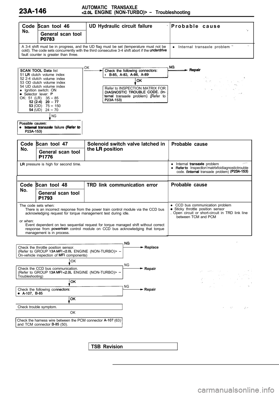
Code Scan tool 46UD Hydraulic circuit failure P r o b a b l e c a u s e
No.General scan tool
A 3-4 shift must be in progress, and the UD flag must be set (temperature must not be
l I n t e r n a l t r a n s a x l e p r o b l e m cold). The code sets concurrently with the third co nsecutive 3-4 shift abort if the fault counter is greater than three.
SCAN TOOL Data list
51
clutch volume index
52 2-4 clutch volume index
53 OD clutch volume index
54 UD clutch volume index
l Ignition switch: ON
Selector lever: OK: 51 (LR)
35 85
52 (2-4) 20 77
53 (OD)
75 150
54 (UD)
24 70
NG
l Internal transaxle (Refer to
OK
.
Refer to INSPECTION MATRIX FOR
transaxle problem) (Refer to
Code Scan tool 47 Solenoid switch valve latched in
Probable cause
No.General scan toolthe position
pressure is high for second time. l
Internal probleml lnspectlon’matrlxfoidiagnostictroublecode. transaxle problem)
Code Scan tool 48
No.General scan tool TRD link communication error
The code sets when:
There is an incorrect response from the power train control module via the CCD bus
acknowledging request for torque management test du ring idle.
or when: Event dependent on two sequential request for torqu e managed shift without correct
response from
control module on CCD bus acknowledging that torqu e
management is in process.
Check the throttle position sensor.
(Refer to GROUP ENGINE (NON-TURBO)> On-vehicle inspection of components)
Replace
OKNGCheck the CCD bus communication. Repair
(Refer to GROUP ENGINE (NON-TURBO)> Troubleshooting)
Check the following coNG Repair
Check trouble symptom.
OK
Check the harness wire between the PCM connector (63) and TCM connector (50).
Probable cause
l CCD bus communication problem Sticky throttle position sensor
. Open circuit or short-circuit in TRD link line
between TCM and PCM
TSB Revision
Page 1161 of 2103
AUTOMATIC TRANSAXLE
ENGINE (NON-TURBO)>:
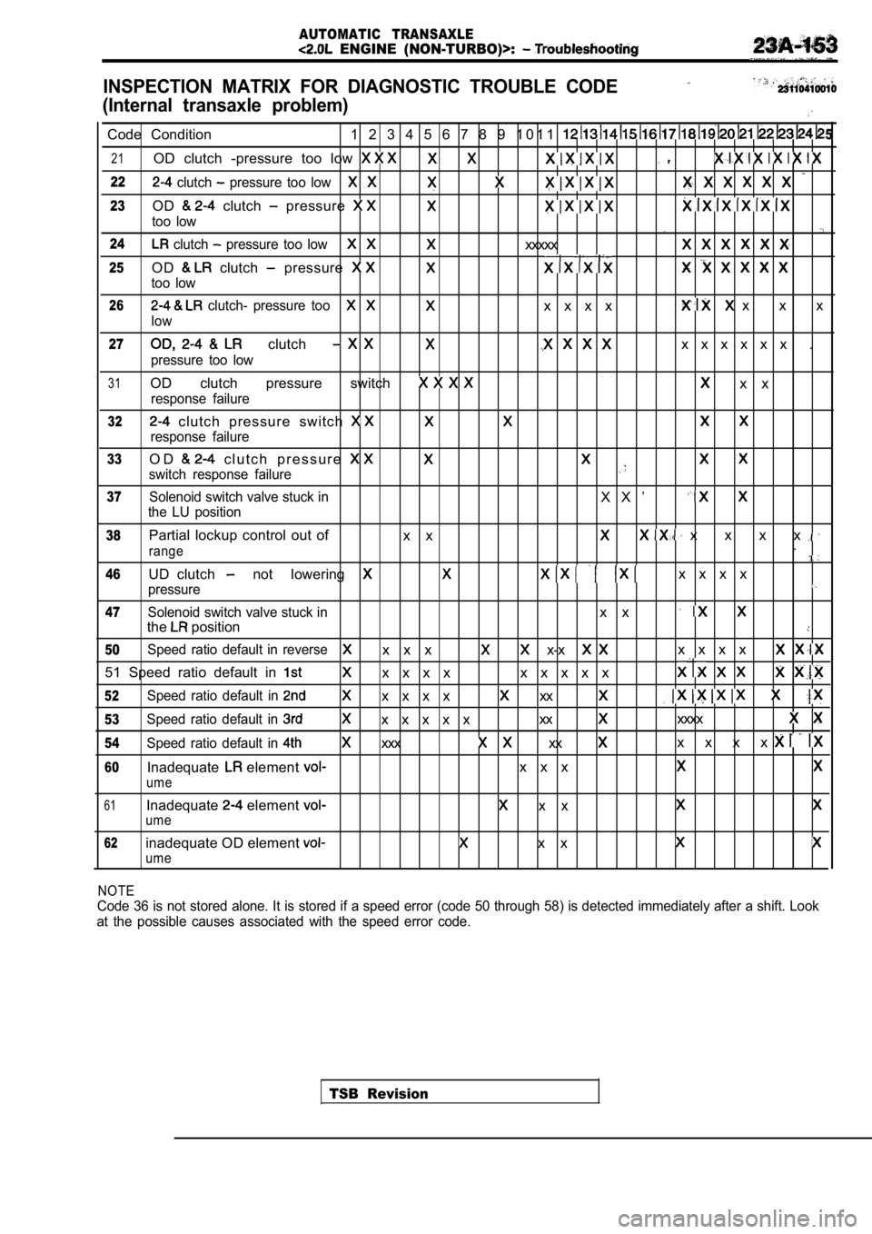
INSPECTION MATRIX FOR DIAGNOSTIC TROUBLE CODE
(Internal transaxle problem)
5Code Condition 1 2 3 4 5 6 7 8 9 1 0 1 1
21OD clutch -pressure too low
22 clutch pressure too low
23OD clutch pressure
too low
24 clutch pressure too lowxxxxx
25O D clutch pressure
too low
26 clutch- pressure toox x x x x x x
low
27 clutch x x x x x x .
pressure too low
31OD clutch pressure switch x x
response failure
32 clutch pressure switch
response failure
33O D c l u t c h p r e s s u r e
switch response failure
37Solenoid switch valve stuck inX X ’
the LU position
38Partial lockup control out of x x x x x x
range.
46UD clutch not lowering x x x x
pressure
47Solenoid switch valve stuck inx x
the position
50Speed ratio default in reversex x x x-x x x x x
51 Speed ratio default in x x x x x x x x x
52Speed ratio default in x x x xxx
53Speed ratio default in x x x x xxxxxxx
54Speed ratio default in xxx xx x x x x
60Inadequate element x x x
ume
61Inadequate element x xume
62inadequate OD element x x
ume
TSB Revision
NOTE
Code 36 is not stored alone. It is stored if a spee
d error (code 50 through 58) is detected immediatel y after a shift. Look
at the possible causes associated with the speed er ror code.
Page 1176 of 2103
AUTOMATIC TRANSAXLE
ENGINE On-vehicle Service
Accumulators
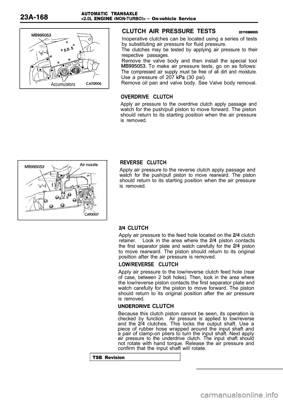
CLUTCH AIR PRESSURE TESTS
Inoperative clutches can be located using a series of tests
by substituting air pressure for fluid pressure.
The clutches may be tested by applying air pressure to their
respective passages.
Remove the valve body and then install the special tool
To make air pressure tests, go on as follows:
The compressed air supply must be free of all dirt and moisture.
Use a pressure of 207 (30 psi).
Remove oil pan and valve body. See Valve body remov al.
OVERDRIVE CLUTCH
Apply air pressure to the overdrive clutch apply passage and
watch for the push/pull piston to move forward. The piston
should return to its starting position when the air pressure
is removed.
REVERSE CLUTCH
Apply air pressure to the reverse clutch apply pass age and
watch for the push/pull piston to move rearward. Th e piston
should return to its starting position when the air pressure
is removed.
CLUTCH
Apply air pressure to the feed hole located on the clutch
retainer.Look in the area where the piston contacts
the first separator plate and watch carefully for the piston
to move rearward. The piston should return to its o riginal
position after the air pressure is removed.
LOW/REVERSE CLUTCH
Apply air pressure to the low/reverse clutch feed h ole (rear
of case, between 2 bolt holes). Then, look in the a rea where
the low/reverse piston contacts the first separator plate and
watch carefully for the piston to move forward. The piston
should return to its original position after the ai r pressure
is removed.
CLUTCH
Because this clutch piston cannot be seen, its oper ation is
checked by function. Air pressure is applied to low/ reverse
and the clutches. This locks the output shaft. Use a
piece of rubber hose wrapped around the input shaft and
a pair of clamp-on pliers to turn the input shaft. Next apply
air pressure to the underdrive clutch. The input sh aft should
not rotate with hand torque. Release the air pressu re and
confirm that the input shaft will rotate.
TSB Revision
Page 1246 of 2103
AUTOMATIC TRANSAXLE
OVERHAUL. .
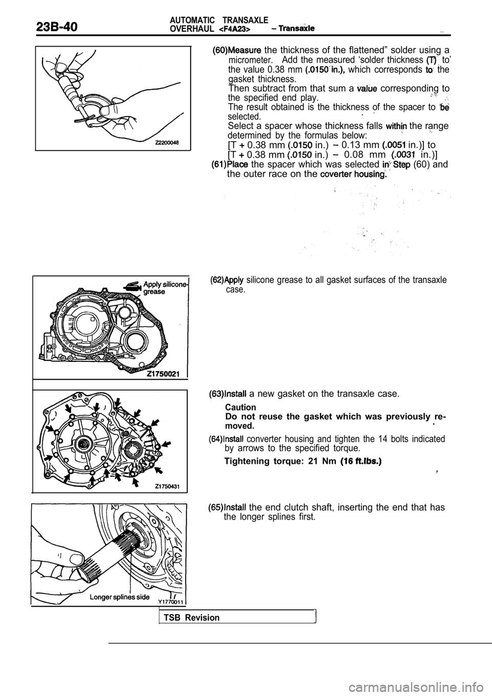
the thickness of the flattened” solder using a
micrometer.Add the measured ‘solder thickness to’
the value 0.38 mm
which corresponds the
gasket thickness.
Then subtract from that sum a corresponding to
the specified end play.
The result obtained is the thickness of the spacer to
selected..
Select a spacer whose thickness falls the range
determined by the formulas below:
[T 0.38 mm in.) 0.13 mm in.)] to
[T
0.38 mm in.) 0.08 mm in.)]
the spacer which was selected (60) and
the outer race on the
silicone grease to all gasket surfaces of the tran saxle
case.
a new gasket on the transaxle case.
Caution
Do not reuse the gasket which was previously re-
moved..
converter housing and tighten the 14 bolts indicat ed
by arrows to the specified torque.
Tightening torque: 21 Nm
the end clutch shaft, inserting the end that has
the longer splines first.
TSB Revision
Page 1286 of 2103
AUTOMATIC TRANSAXLE
OVERHAUL
General
Precautions to be taken when disassembling and the
Because the automatic transaxle is of component parts of especially high degree of
precision, these parts should be very carefully han dled during disassembly and assembly so as not
to scar or scratch them.
A rubber mat should be placed on the and it should always be kept clean.
During disassembly, cloth gloves or shop towels, sh ould not be used.
such items must be used,
either use articles made of nylon, or use paper tow els.
All disassembled parts must be thoroughly cleaned.
Metal parts may be cleaned with ordinary but must thoroughly air dried.
Clean the clutch disc, resin thrust plate and rubbe r parts by using ATF (automatic transmission fluid) ,
being very careful that dust, dirt, etc. do not adhere to them.
Do not reuse gaskets, oil seals, or, rubber parts.
Replace such parts with new ones at every reassembl y. The oil’ gauge need not
be replaced.
Do not use grease other than petrolatum jelly.
Apply ATF to friction components, rotating
and sliding parts before installation.
A new clutch disc should be immersed in ATF for at least two hours before installation.
Do not apply sealer or adhesive to gaskets.
When a bushing must be replaced, replace the assemb ly in which it is incorporated:,
If the transaxle main unit is damaged, also disasse
mble and clean the ‘cooler system.,
TSB Revision
Page 1325 of 2103
AUTOMATIC
OVERHAUL Transaxle
A
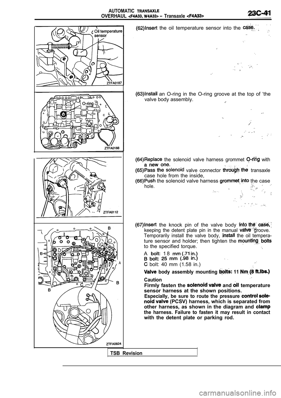
the oil temperature sensor into the
,
an O-ring in the O-ring groove at the top of ‘the
valve body assembly.
the solenoid valve harness grommet with
valve connector transaxle
case hole from the inside,
the solenoid valve harness the case
hole.
the knock pin of the valve body
keeping the detent plate pin in the manual groove.
Temporarily install the valve body,
the oil tempera-
ture sensor and holder; then tighten the
to the specified torque.
A 1 8
bolt: 40 mm (1.58 in.)
body assembly mounting 11
Caution
Firmly fasten the and temperature
sensor harness at the shown positions.
Especially, be sure to route the pressure
(PCSV) harness, which is separated from
other harness, as shown in the diagram and
the harness. Failure to fasten it may result in con tact
with the detent plate or parking rod.
TSB Revision
Page 1356 of 2103
AUTOMATIC TRANSAXLE
OVERHAUL -Transaxle
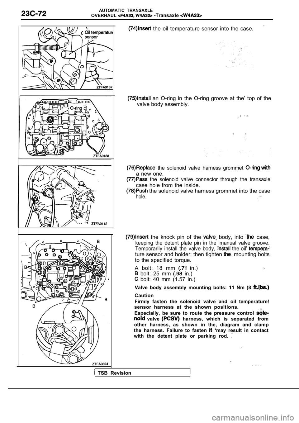
the oil temperature sensor into the case.
an O-ring in the O-ring groove at the’ top of the
valve body assembly.
the solenoid valve harness grommet
a new one.
the solenoid valve connector through the transaxle
case hole from the inside.
the solenoid valve harness grommet into the case
hole.
the knock pin of the body, into case,
keeping the detent plate pin in the ‘manual valve g roove.
Temporarily install the valve body,
the oil’
ture sensor and holder; then tighten mounting bolts
to the specified torque.
A bolt: 18 mm
in.)
bolt: 25 mm in.)
bolt: 40 mm (1.57 in.)
Valve body assembly mounting bolts: 11 Nm (8
Caution
Firmly fasten the solenoid valve and oil temperatur e!
sensor harness at the shown positions.
Especially, be sure to route the pressure control
valve harness, which is separated from
other harness, as shown in the, diagram and clamp
the harness. Failure to fasten
‘may result in contact
with the detent plate or parking rod.
TSB Revision